EP0247325A2 - Filtering device - Google Patents
Filtering device Download PDFInfo
- Publication number
- EP0247325A2 EP0247325A2 EP87104664A EP87104664A EP0247325A2 EP 0247325 A2 EP0247325 A2 EP 0247325A2 EP 87104664 A EP87104664 A EP 87104664A EP 87104664 A EP87104664 A EP 87104664A EP 0247325 A2 EP0247325 A2 EP 0247325A2
- Authority
- EP
- European Patent Office
- Prior art keywords
- filter
- pressure
- pump
- frame
- liquid
- Prior art date
- Legal status (The legal status is an assumption and is not a legal conclusion. Google has not performed a legal analysis and makes no representation as to the accuracy of the status listed.)
- Granted
Links
- 238000001914 filtration Methods 0.000 title abstract description 3
- 239000007788 liquid Substances 0.000 claims description 13
- 238000000034 method Methods 0.000 claims description 11
- 238000004140 cleaning Methods 0.000 claims description 4
- 230000008878 coupling Effects 0.000 claims description 4
- 238000010168 coupling process Methods 0.000 claims description 4
- 238000005859 coupling reaction Methods 0.000 claims description 4
- 239000000706 filtrate Substances 0.000 claims description 3
- XLYOFNOQVPJJNP-UHFFFAOYSA-N water Substances O XLYOFNOQVPJJNP-UHFFFAOYSA-N 0.000 description 7
- 229910001220 stainless steel Inorganic materials 0.000 description 3
- 239000010935 stainless steel Substances 0.000 description 3
- 239000000725 suspension Substances 0.000 description 3
- 238000007789 sealing Methods 0.000 description 2
- 238000005260 corrosion Methods 0.000 description 1
- 230000007797 corrosion Effects 0.000 description 1
- 239000000463 material Substances 0.000 description 1
Images


Classifications
-
- B—PERFORMING OPERATIONS; TRANSPORTING
- B01—PHYSICAL OR CHEMICAL PROCESSES OR APPARATUS IN GENERAL
- B01D—SEPARATION
- B01D35/00—Filtering devices having features not specifically covered by groups B01D24/00 - B01D33/00, or for applications not specifically covered by groups B01D24/00 - B01D33/00; Auxiliary devices for filtration; Filter housing constructions
- B01D35/26—Filters with built-in pumps filters provided with a pump mounted in or on the casing
-
- B—PERFORMING OPERATIONS; TRANSPORTING
- B01—PHYSICAL OR CHEMICAL PROCESSES OR APPARATUS IN GENERAL
- B01D—SEPARATION
- B01D35/00—Filtering devices having features not specifically covered by groups B01D24/00 - B01D33/00, or for applications not specifically covered by groups B01D24/00 - B01D33/00; Auxiliary devices for filtration; Filter housing constructions
- B01D35/02—Filters adapted for location in special places, e.g. pipe-lines, pumps, stop-cocks
- B01D35/027—Filters adapted for location in special places, e.g. pipe-lines, pumps, stop-cocks rigidly mounted in or on tanks or reservoirs
- B01D35/0273—Filtering elements with a horizontal or inclined rotation or symmetry axis submerged in tanks or reservoirs
-
- B—PERFORMING OPERATIONS; TRANSPORTING
- B01—PHYSICAL OR CHEMICAL PROCESSES OR APPARATUS IN GENERAL
- B01D—SEPARATION
- B01D35/00—Filtering devices having features not specifically covered by groups B01D24/00 - B01D33/00, or for applications not specifically covered by groups B01D24/00 - B01D33/00; Auxiliary devices for filtration; Filter housing constructions
- B01D35/30—Filter housing constructions
Definitions
- the present invention relates to a filter device which is arranged in the liquid to be filtered and releases the filtrate directly into this liquid.
- the present invention relates to an underwater filter device.
- Underwater filter devices which draw water to be cleaned through a filter by means of a pump and in which the cleaned water is then returned directly from the pressure side of the pump into the basin. These devices have the disadvantage that they are limited in terms of performance and that the filters are relatively cumbersome to replace, since the filters have to be uncoupled from the device on both the suction and the discharge side. This requires double sealing devices and possibly even double coupling devices.
- the delivery side of the filter is free, i.e. there is no significant length lead on the discharge side. Rather, the filtrate is released from the filter essentially directly in the container from which it was sucked in. If, in the embodiment of the invention with two pumps, the two discharge sides are connected to the same filter, this enables a flexible working method, in which one can work with both peak loads and continuous operation.
- the intake sides of the two filters can also be connected in parallel with an intake port.
- the arrangement of the individual elements with respect to the filter is such that, by loosening the connection between the filter and the rest of the device, it can fall freely out of the device and in this way can get into a filter receptacle.
- the filter will expediently hang vertically under the connecting device, so that the filter automatically frees itself from the device when the connection is released and can fall into a receptacle.
- a substantially cylindrical filter is particularly suitable, which is connected to the rest of the device on the end face.
- the with the container liquid in Contacting parts of the device made of inert, corrosion-resistant material, especially stainless steel or stainless steel.
- the underwater filter device 1 is arranged on the bottom 101 of a container 100. Water to be cleaned is sucked in through the suction nozzle 3 arranged in the vicinity of the floor 101, which is connected by means of lines 4, 4 ⁇ to the suction side of a pump 5, 5 ⁇ .
- Two pumps 5 and 5 ⁇ are provided, which are connected in parallel in order to be able to switch over different operating states, namely continuous operation with the additional security, if one pump 5 or 5 ⁇ fails to the other pump 5 ⁇ or 5, and peak operation, in which both Pumps 5 and 5 ⁇ work simultaneously and in parallel.
- a connecting device 31 or an unlocking and locking device 31 is also fastened to the frame 21.
- three guide plates 33 are attached, which have a beveled run-up surface 35.
- the connecting device 31 has three hooks 37 rotatably mounted on the guide plates 33 at 34. By pivoting the hooks 37, the flanges 15 and 17 are either pressed firmly together and connected to one another, whereby an elastic seal (not shown) arranged between the flanges 15 and 17 comes into sealing engagement with the flanges 15 and 17, or the flanges 15 and 17 be released.
- the device 1 on the suspension bracket 27 is then raised by means of a hook (not shown) and moved over a filter receptacle. As a result of this lifting, the device tilts and the curved end sections 231 and 231 ⁇ hang down, as does the filter 11.
- two tabs 470, 470 ⁇ are attached to the frame tube element 21 shaped as an inverted V.
- these tabs 470, 470 ⁇ each have an opening 471, 471 ⁇ attached, which serves to receive the lifting element on the suspension cable with which the device can then be moved into the liquid container as described above.
- the advantage of attaching two fastening elements in this embodiment is that the movement of the device can thus be better controlled.
Landscapes
- Chemical & Material Sciences (AREA)
- Chemical Kinetics & Catalysis (AREA)
- Filtration Of Liquid (AREA)
- Farming Of Fish And Shellfish (AREA)
- External Artificial Organs (AREA)
- Separation Using Semi-Permeable Membranes (AREA)
- Separation By Low-Temperature Treatments (AREA)
- Centrifugal Separators (AREA)
- Surgical Instruments (AREA)
Abstract
Description
Die vorliegende Erfindung bezieht sich auf eine Filtervorrichtung, die in der zu filternden Flüssigkeit angeordnet ist, und das Filtrat direkt wieder in diese Flüssigkeit abgibt. Insbesondere bezieht sich die vorliegende Erfindung auf eine Unterwasser-Filtervorrichtung.The present invention relates to a filter device which is arranged in the liquid to be filtered and releases the filtrate directly into this liquid. In particular, the present invention relates to an underwater filter device.
Es sind bereits Unterwasser-Filtervorrichtungen bekannt, die mittels einer Pumpe zu reinigendes Wasser durch ein Filter ansaugen und bei denen das gereinigte Wasser dann von der Druckseite der Pumpe in das Becken direkt rückgeführt wird. Diese Vorrichtungen haben den Nachteil, daß sie von der Leistung her begrenzt sind, und daß ein Auswechseln der Filter relativ umständlich ist, da die Filter sowohl an der Ansaug- als auch an der Abgabeseite von der Vorrichtung abgekoppelt werden müssen. Das erfordert doppelte Dichtungseinrichtungen und gegebenenfalls sogar doppelte Kopplungseinrichtungen.Underwater filter devices are already known which draw water to be cleaned through a filter by means of a pump and in which the cleaned water is then returned directly from the pressure side of the pump into the basin. These devices have the disadvantage that they are limited in terms of performance and that the filters are relatively cumbersome to replace, since the filters have to be uncoupled from the device on both the suction and the discharge side. This requires double sealing devices and possibly even double coupling devices.
Aufgabe der vorliegenden Erfindung ist es daher, eine einfache Filtervorrichtung zu schaffen, bei der das Auswechseln der Filter rasch und problemlos durchgeführt werden kann. Weiterhin soll bei der Filtervorrichtung in einfacher Weise eine Kontrolle des Filterzustandes ermöglicht werden, damit die Filter zur rechten Zeit ausgetauscht werden können. Eine weitere Aufgabe der Erfindung besteht darin, ein Verfahren zum Filtrieren von Flüssigkeit in einem Behälter zu schaffen, bei dem ein in der zu reinigenden Flüssigkeit befindlicher Filter verwendet wird, und das einen kontinuierlichen Betrieb durch rasches und sicheres Wechseln der Filter ermöglicht.The object of the present invention is therefore to provide a simple filter device in which the filter can be replaced quickly and easily. Furthermore, the filter device should be able to control the filter state in a simple manner so that the filters are replaced at the right time can. Another object of the invention is to provide a method of filtering liquid in a container using a filter in the liquid to be cleaned, and which enables continuous operation by quickly and safely changing the filter.
Diese Aufgaben werden erfindungsgemäß durch Vorrichtungen bzw. Verfahren gelöst, wie sie im einzelnen in den Ansprüchen definiert sind.According to the invention, these objects are achieved by devices or methods as defined in detail in the claims.
Bei der erfindungsgemäßen Vorrichtung ist die Abgabeseite des Filters frei, d.h. es ist an der Abgabeseite keine Ableitung von beträchtlicher Länge vorhanden. Vielmehr wird das Filtrat von dem Filter im wesentlichen direkt in dem Behälter wieder abgegeben, von dem es angesaugt wurde. Wenn bei der Ausführungsform der Erfindung mit zwei Pumpen die beiden Abgabeseiten an denselben Filter angeschlossen werden, so ermöglicht dies eine flexible Arbeitsweise, bei der mit sowohl bei Spitzenbelastung als auch bei Dauerbetrieb gearbeitet werden kann. Auch die Ansaugseiten der beiden Filter können mit einem Ansaugstutzen parallel verbunden werden.In the device according to the invention, the delivery side of the filter is free, i.e. there is no significant length lead on the discharge side. Rather, the filtrate is released from the filter essentially directly in the container from which it was sucked in. If, in the embodiment of the invention with two pumps, the two discharge sides are connected to the same filter, this enables a flexible working method, in which one can work with both peak loads and continuous operation. The intake sides of the two filters can also be connected in parallel with an intake port.
Bei der bevorzugten Ausführungsform der Erfindung ist die Anordnung der einzelnen Elemente in bezug auf den Filter so, daß durch ein Lösen der Verbindung zwischen dem Filter und der übrigen Vorrichtung dieser frei aus der Vorrichtung herausfallen kann und auf diese Weise in einen Filteraufnahmebehälter gelangen kann. Zweckmäßigerweise wird dabei der Filter senkrecht unter der Verbindungseinrichtung hängen, so daß sich der Filter beim Lösen der Verbindung selbständig aus der Vorrichtung befreit und in einen Aufnahmebehälter fallen kann. Besonders geeignet ist dabei ein im wesentlichen zylindrischer Filter, der an der Stirnseite mit der übrigen Vorrichtung verbunden ist.In the preferred embodiment of the invention, the arrangement of the individual elements with respect to the filter is such that, by loosening the connection between the filter and the rest of the device, it can fall freely out of the device and in this way can get into a filter receptacle. The filter will expediently hang vertically under the connecting device, so that the filter automatically frees itself from the device when the connection is released and can fall into a receptacle. A substantially cylindrical filter is particularly suitable, which is connected to the rest of the device on the end face.
Es ist bevorzugt, daß die mit der Behälterflüssigkeit in Berührung kommenden Teile der Vorrichtung aus inertem, korrosionsbeständigem Material, insbesondere aus Edelstahl bzw. rostfreiem Stahl, bestehen.It is preferred that the with the container liquid in Contacting parts of the device made of inert, corrosion-resistant material, especially stainless steel or stainless steel.
Bei der bevorzugten Ausführungsform der Erfindung ist die Vorrichtung so aufgebaut, daß durch bloßes Lösen der Verbindung zwischen Filtereinheit und Pumpe erstere frei und ungehindert aus der Vorrichtung herausfallen kann. Es bedarf dann keiner Betätigung weiterer mechanischer Einrichtung, wie z. B. von Klappen oder Deckeln oder dergleichen.In the preferred embodiment of the invention, the device is constructed in such a way that simply loosening the connection between the filter unit and the pump allows the former to fall out of the device freely and unhindered. There is then no need to operate any other mechanical device such. B. flaps or lids or the like.
Weitere Einzelheiten und bevorzugte Ausführungsformen, sowie Vorteile und Probleme, die durch die erfindungsgemäße Vorrichtung sowie das erfindungsgemäße Verfahren gelöst werden, sind in der folgenden Beschreibung der Zeichnung enthalten. In dieser zeigen:
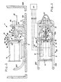
- Fig. 1 eine Draufsicht,
- Fig. 2 eine Seitenansicht,
- Fig. 3 eine Vorderansicht
- 1 is a plan view,
- 2 is a side view,
- Fig. 3 is a front view
Auf dem Boden 101 eines Behälters 100 ist die Unterwasser-Filtervorrichtung 1 angeordnet. Zu reinigendes Wasser wird durch den in der Nähe des Bodens 101 angeordneten Ansaugstutzen 3 angesaugt, der mittels Leitungen 4, 4ʹ mit der Ansaugseite jeweils einer Pumpe 5, 5ʹ verbunden ist. Zwei Pumpen 5 und 5ʹ sind vorgesehen, die parallel geschaltet sind, um verschiedene Betriebszuständ , nämlich Dauerbetrieb mit der zusätzlichen Sicherheit, bei Ausfallen einer Pumpe 5 bzw. 5ʹ auf die andere Pumpe 5ʹ bzw. 5 umschalten zu können, und Spitzenbetrieb, bei dem beide Pumpen 5 und 5ʹ simultan und parallel arbeiten.The underwater filter device 1 is arranged on the
Die Pumpe 5 bzw. 5ʹ gibt das angesaugte, kontaminierte Wasser druckseitig über Verbindungsleitungen 7, 7ʹ 7ʺ und einer Einlaßkammer 9 in das Innere eines hohlzylindrischen Filters 11. Das gefilterte Wasser erreicht von der Außenseite des im kontaminierten Wasser des Behälters 100 angeordneten Filters 11 direkt wieder das Wasser des Behälters 100.The
Der Filter 11 ist mit einem Ansatz 13 verbunden, an dem ein Flansch 15 angebracht ist. Ein Gegenflansch 17 ist an einem kuppelartigen Verteilerelement 19, das die Einlaßkammer 9 umgibt, angebracht. Das Verteilerelement 19 ist ebenso wie die Pumpen 5 und 5ʹ an einem aus Edelstahl-Elementen bestehenden Rohrrahmen 21 befestigt. Dieser Rahmen 21 weist zwei schlittenkufenartig geformte Rohrabschnitte 23, 23ʹ auf, die jeweils aus einem Auflageabschnitt 230, 230ʹ und einem gebogenen Endabschnitt 231, 231ʹ bestehen. An dem dem Endabschnitt 231, 231ʹ gegenüberliegenden Ende der Vorrichtung ist an dem Rahmen 21 ein Aufhängebügel 27 befestigt, an dem die Unterwasser-Filtervorrichtung 1 gehoben und bewegt werden kann.The
An dem Rahmen 21 ist auch eine Verbindungseinrichtung 31 bzw. eine Ent- und Verriegelungseinrichtung 31 befestigt. An dem Flansch 17 sind drei Führungsplatten 33 angebracht, die eine abgeschrägte Auflauffläche 35 aufweisen. Die Verbindungseinrichtung 31 weist drei an den Führungsplatten 33 bei 34 drehbar gelagerte Haken 37 auf. Durch ein Schwenken der Haken 37 werden die Flansche 15 und 17 entweder fest aneinandergedrückt und miteinander verbunden, wodurch eine nicht dargestellte, zwischen den Flanschen 15 und 17 angeordnete elastische Dichtung in dichtenden Eingriff mit den Flanschen 15 und 17 gerät, oder die Flansche 15 und 17 werden freigegeben.A connecting
Das jeweilige freie Ende des drehbar gelagerten Hakens 37 ist über jeweils eine Führungsstange 39 mit einer zentralen Hülse 41 verbunden. Nur eine der drei Führungsstangen 39, die alle mit der Hülse 41 bei 49 drehbar verbunden sind, ist in der Zeichnung gezeigt. Die Hülse 41 ist mittels eines Innengewindes längs der Gewindestange 43, auf die die Hülse 41 geschraubt ist, bewegbar. Die Gewindestange 43 ist fest mit der Achse oder Welle eines Motors 45 verbunden. Das freie Ende der Gewindestange 43 ist in einem Lager 47 gelagert, welches mit dem kuppelförmigen Verteilerelement 19 verbunden ist. Beim Laufen des Motors 45 in einer Richtung werden daher die Haken 37 nach innen zum Ankuppeln des Flansches 15 und des Filters 11 bewegt. Beim Laufen des Motors in der anderen Richtung dagegen werden die Haken 37 nach außen geschwenkt, wodurch der Filter 11 samt Ansatz 13 und Flansch 15 freigegeben wird.The respective free end of the rotatably mounted
In der Verteilerkammer bzw. an der Druckseite der Pumpen 5 und 5ʹ ist ein Drucksensor 51 angeordnet, der ein dem Druck im Filter 11 entsprechendes Signal erzeugt. Wenn dieses Signal einen Druck repräsentiert, der einen Grenzwert überschreitet, dann werden die Pumpen 5 bzw. 5ʹ von der Steuervorrichtung 61 ausgeschaltet, mit der der Drucksensor operativ verbunden ist.In the distribution chamber or on the pressure side of the
Mittels eines nicht dargestellten Hakens wird dann die Vorrichtung 1 an dem Aufhängebügel 27 angehoben und über einen Filteraufnahmebehälter bewegt. Durch dieses Anheben kippt die Vorrichtung, und die gebogenen Endabschnitte 231 bzw. 231ʹ hängen ebenso wie das Filter 11 nach unten.The device 1 on the
Der Motor 45 wird nun von der Steuereinrichtung 61 betätigt, so daß die aus Filter 11, Ansatz 13 und Flansch 15 bestehende Einheit von der Vorrichtung durch Verschwenken der Haken 37 gelöst wird und von der Vorrichtung 1 abfällt und in den Filteraufnahmebehälter fällt. Von dort aus kann die Einheit entweder beseitigt oder weiterverarbeitet, z. B. gereinigt werden. Die Vorrichtung 1 wird nun mit Flansch 17 auf eine saubere, noch nicht verstopfte Filtereinheit aufgesetzt. Dabei wird das genaue Ausrichten der Flansche 15 und 17 durch die Auflaufflächen 35 der Platten 33 erleichtert und automatisiert. Durch umgekehrtes Laufen des Motors 45, gesteuert von der Steuerung 61, wird dann die neue Filtereinheit durch ein Verschwenken der Haken 37 angekoppelt. Die Vorrichtung 1 wird dann wieder auf den Boden 101 des Behälters 100 abgesenkt. Die gebogenen Endabschnitte 231, 231ʹ sorgen dabei bei Berührung des Bodens 101 dafür, daß die Vorrichtung auf die geraden Abschnitte 230, 230ʹ der Kufen 23, 23ʹ zu stehen kommt. Der Reinigungsprozeß kann nun wieder beginnen.The
Bei den weiteren in den Fig. 3 bis 5 in den drei Ansichten dargestellten Ausführungsformen der erfindungsgemäßen Anordnung wurden weitestgehend dieselben Bezugszeichen verwendet wie in der Ausführungsform gemäß Fig. 1 und 2. Bei dieser Ausführungsform sind zwei Ansaugstutzen 3 und 3ʹ vorgesehen. Der Motor 45 ist bei der Darstellung dieser Ausführungsform weggelassen. Dieser Motor kann auf die Steckeinrichtung 450 gesteckt werden, wobei die Arretierung über eine einfache Schnappkupplung mit den Schlitzen 451 erfolgt und der Motor die Welle 452 antreibt.In the further embodiments of the arrangement according to the invention shown in FIGS. 3 to 5 in the three views, largely the same reference numerals have been used as in the embodiment according to FIGS. 1 and 2. In this embodiment, two
Das Filter 11 ist in Fig. 3 mit zusätzlichen Details dargestellt. An der Flanschplatte 15 sind eine Mehrzahl Filterelemente 110 mittels einer bajonettartigenBefestigung angeordnet. Diese Filterelemente 110 werden durch eine Andruckplatte 112 gegen die Flanschplatt 15 gedrückt und in dieser Position gehalten. Die Andruckplatte 112 wird durch vier Andruckstangen 114 (nur eine in Fig. 3 dargestellt) gegen die Flanschplatte 5 gezogen.The
Die Pumpen 5 und 5ʹ sind bei der in Fig. 3 bis 5 gezeigten Ausführungsform etwas höher angeordnet und die beiden Ansaugstutzen 3 sind mit der Ansaugseite der Pumpe über die Leitung 230 und die nach oben führende Verbindungsleitung 234 verbunden.The
An dem als umgekehrtes V geformten Rahmen-Rohrelement 21 sind bei dieser Ausführungsform zwei Laschen 470, 470ʹ befestigt. In diesen Laschen 470, 470ʹ ist jeweils eine Öffnung 471, 471ʹ angebracht, die zur Aufnahme des Hebe elementes am Trageseil dient, mit dem die Einrichtung dann in den Flüssigkeitsbehälter wie oben beschrieben bewegt werden kann. Der Vorteil der Anbringung zweier Befestigungselemente in dieser Ausführungsform besteht darin, daß die Bewegung der Vorrichtung damit besser gesteuert werden kann.In this embodiment, two
Claims (15)
daß der Druck an der Filtereingangsseite automatisch festgestellt wird und daß ein diEsem Druck entsprechendes Signal erzeugt wird
, daß dieses Signal einer Steuereinrichtung aufgegeben wird,
daß die Steuereinrichtung ein Steuersignal abgibt, welches die Pumpe bzw. Pumpen dann ausschaltet, wenn das Drucksignal einen Druck repräsentiert, der einen vorgegebenen Druckgrenzwert übersteigt.15. The method according to any one of the preceding method claims, characterized in
that the pressure on the filter inlet side is determined automatically and that a signal corresponding to this pressure is generated
that this signal is given to a control device,
that the control device emits a control signal which switches the pump or pumps off when the pressure signal represents a pressure which exceeds a predetermined pressure limit.
Priority Applications (1)
| Application Number | Priority Date | Filing Date | Title |
|---|---|---|---|
| AT87104664T ATE78711T1 (en) | 1986-05-27 | 1987-03-30 | FILTERING DEVICE. |
Applications Claiming Priority (2)
| Application Number | Priority Date | Filing Date | Title |
|---|---|---|---|
| DE3617739A DE3617739C2 (en) | 1986-05-27 | 1986-05-27 | Filter device, in particular underwater filter device and filtering method |
| DE3617739 | 1986-05-27 |
Publications (3)
| Publication Number | Publication Date |
|---|---|
| EP0247325A2 true EP0247325A2 (en) | 1987-12-02 |
| EP0247325A3 EP0247325A3 (en) | 1988-08-10 |
| EP0247325B1 EP0247325B1 (en) | 1992-07-29 |
Family
ID=6301702
Family Applications (1)
| Application Number | Title | Priority Date | Filing Date |
|---|---|---|---|
| EP87104664A Expired - Lifetime EP0247325B1 (en) | 1986-05-27 | 1987-03-30 | Filtering device |
Country Status (4)
| Country | Link |
|---|---|
| EP (1) | EP0247325B1 (en) |
| AT (1) | ATE78711T1 (en) |
| DE (2) | DE3617739C2 (en) |
| ES (1) | ES2033251T3 (en) |
Cited By (2)
| Publication number | Priority date | Publication date | Assignee | Title |
|---|---|---|---|---|
| DE4118432A1 (en) * | 1991-06-05 | 1992-12-10 | Pall Corp | Filter with rapidly and safely exchangeable filter element - with filter retention device between holder plates, useful for fluid contg. radioactive material and for nuclear power plant water cooling circuit |
| CN102441299A (en) * | 2010-10-05 | 2012-05-09 | 卡尔德·加布尔加德 | Floatable cleaning assembly |
Families Citing this family (1)
| Publication number | Priority date | Publication date | Assignee | Title |
|---|---|---|---|---|
| DE19846591C2 (en) | 1998-10-09 | 2001-06-13 | Keld Gabelgaard | Process for flushing rod elements and use of the process for cleaning fuel elements |
Citations (4)
| Publication number | Priority date | Publication date | Assignee | Title |
|---|---|---|---|---|
| US1813601A (en) * | 1929-07-29 | 1931-07-07 | Standard Oil Co | Filter opening means |
| FR1594001A (en) * | 1967-12-04 | 1970-06-01 | ||
| AU425195B2 (en) * | 1969-03-14 | 1972-06-09 | Marvel Engineering Company | Air-operated filtering system |
| DE3320619A1 (en) * | 1983-02-08 | 1984-08-09 | Andreas 4040 Neuss Krüll | Compact swimming pool filter plant - has immersed motor pump below filters, detachably linked with filter pipe and return pipe |
Family Cites Families (2)
| Publication number | Priority date | Publication date | Assignee | Title |
|---|---|---|---|---|
| DE257612C (en) * | ||||
| DE284116C (en) * | 1900-01-01 |
-
1986
- 1986-05-27 DE DE3617739A patent/DE3617739C2/en not_active Expired - Lifetime
-
1987
- 1987-03-30 ES ES198787104664T patent/ES2033251T3/en not_active Expired - Lifetime
- 1987-03-30 EP EP87104664A patent/EP0247325B1/en not_active Expired - Lifetime
- 1987-03-30 AT AT87104664T patent/ATE78711T1/en not_active IP Right Cessation
- 1987-03-30 DE DE8787104664T patent/DE3780706D1/en not_active Expired - Lifetime
Patent Citations (4)
| Publication number | Priority date | Publication date | Assignee | Title |
|---|---|---|---|---|
| US1813601A (en) * | 1929-07-29 | 1931-07-07 | Standard Oil Co | Filter opening means |
| FR1594001A (en) * | 1967-12-04 | 1970-06-01 | ||
| AU425195B2 (en) * | 1969-03-14 | 1972-06-09 | Marvel Engineering Company | Air-operated filtering system |
| DE3320619A1 (en) * | 1983-02-08 | 1984-08-09 | Andreas 4040 Neuss Krüll | Compact swimming pool filter plant - has immersed motor pump below filters, detachably linked with filter pipe and return pipe |
Cited By (3)
| Publication number | Priority date | Publication date | Assignee | Title |
|---|---|---|---|---|
| DE4118432A1 (en) * | 1991-06-05 | 1992-12-10 | Pall Corp | Filter with rapidly and safely exchangeable filter element - with filter retention device between holder plates, useful for fluid contg. radioactive material and for nuclear power plant water cooling circuit |
| CN102441299A (en) * | 2010-10-05 | 2012-05-09 | 卡尔德·加布尔加德 | Floatable cleaning assembly |
| CN102441299B (en) * | 2010-10-05 | 2015-10-21 | 卡尔德·加布尔加德 | Floatable cleaning assembly |
Also Published As
| Publication number | Publication date |
|---|---|
| DE3617739A1 (en) | 1987-12-03 |
| ATE78711T1 (en) | 1992-08-15 |
| DE3780706D1 (en) | 1992-09-03 |
| EP0247325B1 (en) | 1992-07-29 |
| ES2033251T3 (en) | 1993-03-16 |
| EP0247325A3 (en) | 1988-08-10 |
| DE3617739C2 (en) | 1996-05-30 |
Similar Documents
| Publication | Publication Date | Title |
|---|---|---|
| EP0989255B1 (en) | Cleaning apparatus for swimming-pool | |
| EP1237640B1 (en) | Backflush filter device | |
| DE3441891A1 (en) | METHOD AND DEVICE FOR SUCTIONING SECRETARY LIQUID FROM A Wound | |
| EP0538191A1 (en) | Coffee machine | |
| AT407955B (en) | ARRANGEMENT TO REFILL BLOOD | |
| DE3902943C2 (en) | ||
| DE102009012444A1 (en) | Fluid e.g. waste water, filtering device for use in e.g. industrial system, has rinsing openings attached to filter chamber such that dry sludges together with portions of fluid are partially delivered through rinsing openings | |
| DE60014451T2 (en) | FILTER DEVICE FOR LIQUID SUBSTANCES SUITABLE FOR USE IN MEAT INJECTION MACHINES | |
| DE3134861C2 (en) | Magnetic filter | |
| DE69019614T2 (en) | Filters for automatic cleaning of liquid circuits. | |
| DE3042619C2 (en) | Device for sewer and pit cleaning | |
| EP0247325B1 (en) | Filtering device | |
| DE3937378C2 (en) | ||
| EP0629749A2 (en) | Apparatus for cleaning of sewer conduits | |
| DE1436302B2 (en) | Precoat filter | |
| EP0245715A2 (en) | Apparatus for the treatment of liquids containing impurities, residues and/or ageing products | |
| DE4303783C2 (en) | Process for cleaning transformer oils and arrangement for carrying out the process | |
| DE2831821C3 (en) | Filters for an aquarium | |
| DE2124083C3 (en) | Device for cleaning a mop | |
| DE1621604B1 (en) | Device for cleaning, especially of soiled workpieces | |
| DE3300596C1 (en) | Screening plant for the mechanical cleaning of water flowing in an open channel | |
| EP0280648A1 (en) | Cleaning device for sewage treatment basins | |
| EP0041717B1 (en) | Apparatus for the purification of scalding water | |
| DE1298081B (en) | Discharge device for a suction filter | |
| WO2021180277A1 (en) | Pre-filter unit and cleaning system |
Legal Events
| Date | Code | Title | Description |
|---|---|---|---|
| PUAI | Public reference made under article 153(3) epc to a published international application that has entered the european phase |
Free format text: ORIGINAL CODE: 0009012 |
|
| AK | Designated contracting states |
Kind code of ref document: A2 Designated state(s): AT BE CH DE ES FR GB IT LI NL SE |
|
| PUAL | Search report despatched |
Free format text: ORIGINAL CODE: 0009013 |
|
| AK | Designated contracting states |
Kind code of ref document: A3 Designated state(s): AT BE CH DE ES FR GB IT LI NL SE |
|
| 17P | Request for examination filed |
Effective date: 19890123 |
|
| 17Q | First examination report despatched |
Effective date: 19901012 |
|
| GRAA | (expected) grant |
Free format text: ORIGINAL CODE: 0009210 |
|
| AK | Designated contracting states |
Kind code of ref document: B1 Designated state(s): AT BE CH DE ES FR GB IT LI NL SE |
|
| REF | Corresponds to: |
Ref document number: 78711 Country of ref document: AT Date of ref document: 19920815 Kind code of ref document: T |
|
| ITF | It: translation for a ep patent filed | ||
| REF | Corresponds to: |
Ref document number: 3780706 Country of ref document: DE Date of ref document: 19920903 |
|
| GBT | Gb: translation of ep patent filed (gb section 77(6)(a)/1977) | ||
| ET | Fr: translation filed | ||
| REG | Reference to a national code |
Ref country code: ES Ref legal event code: FG2A Ref document number: 2033251 Country of ref document: ES Kind code of ref document: T3 |
|
| PLBE | No opposition filed within time limit |
Free format text: ORIGINAL CODE: 0009261 |
|
| STAA | Information on the status of an ep patent application or granted ep patent |
Free format text: STATUS: NO OPPOSITION FILED WITHIN TIME LIMIT |
|
| 26N | No opposition filed | ||
| EAL | Se: european patent in force in sweden |
Ref document number: 87104664.5 |
|
| REG | Reference to a national code |
Ref country code: GB Ref legal event code: IF02 |
|
| PGFP | Annual fee paid to national office [announced via postgrant information from national office to epo] |
Ref country code: NL Payment date: 20030317 Year of fee payment: 17 |
|
| PGFP | Annual fee paid to national office [announced via postgrant information from national office to epo] |
Ref country code: AT Payment date: 20030321 Year of fee payment: 17 |
|
| PG25 | Lapsed in a contracting state [announced via postgrant information from national office to epo] |
Ref country code: AT Free format text: LAPSE BECAUSE OF NON-PAYMENT OF DUE FEES Effective date: 20040330 |
|
| PG25 | Lapsed in a contracting state [announced via postgrant information from national office to epo] |
Ref country code: NL Free format text: LAPSE BECAUSE OF NON-PAYMENT OF DUE FEES Effective date: 20041001 |
|
| NLV4 | Nl: lapsed or anulled due to non-payment of the annual fee |
Effective date: 20041001 |
|
| PG25 | Lapsed in a contracting state [announced via postgrant information from national office to epo] |
Ref country code: IT Free format text: LAPSE BECAUSE OF NON-PAYMENT OF DUE FEES;WARNING: LAPSES OF ITALIAN PATENTS WITH EFFECTIVE DATE BEFORE 2007 MAY HAVE OCCURRED AT ANY TIME BEFORE 2007. THE CORRECT EFFECTIVE DATE MAY BE DIFFERENT FROM THE ONE RECORDED. Effective date: 20050330 |
|
| PGFP | Annual fee paid to national office [announced via postgrant information from national office to epo] |
Ref country code: FR Payment date: 20060308 Year of fee payment: 20 |
|
| PGFP | Annual fee paid to national office [announced via postgrant information from national office to epo] |
Ref country code: CH Payment date: 20060329 Year of fee payment: 20 Ref country code: GB Payment date: 20060329 Year of fee payment: 20 |
|
| PGFP | Annual fee paid to national office [announced via postgrant information from national office to epo] |
Ref country code: DE Payment date: 20060406 Year of fee payment: 20 |
|
| PGFP | Annual fee paid to national office [announced via postgrant information from national office to epo] |
Ref country code: ES Payment date: 20060425 Year of fee payment: 20 |
|
| PGFP | Annual fee paid to national office [announced via postgrant information from national office to epo] |
Ref country code: BE Payment date: 20060509 Year of fee payment: 20 |
|
| PG25 | Lapsed in a contracting state [announced via postgrant information from national office to epo] |
Ref country code: GB Free format text: LAPSE BECAUSE OF EXPIRATION OF PROTECTION Effective date: 20070329 |
|
| PG25 | Lapsed in a contracting state [announced via postgrant information from national office to epo] |
Ref country code: ES Free format text: LAPSE BECAUSE OF EXPIRATION OF PROTECTION Effective date: 20070331 |
|
| REG | Reference to a national code |
Ref country code: CH Ref legal event code: PL |
|
| EUG | Se: european patent has lapsed | ||
| REG | Reference to a national code |
Ref country code: ES Ref legal event code: FD2A Effective date: 20070331 |
|
| BE20 | Be: patent expired |
Owner name: *GABELGAARD KELD Effective date: 20070330 |
|
| PGFP | Annual fee paid to national office [announced via postgrant information from national office to epo] |
Ref country code: SE Payment date: 20060306 Year of fee payment: 20 |