EP0247028B1 - Bremsanordnung für anhänger - Google Patents
Bremsanordnung für anhänger Download PDFInfo
- Publication number
- EP0247028B1 EP0247028B1 EP85904819A EP85904819A EP0247028B1 EP 0247028 B1 EP0247028 B1 EP 0247028B1 EP 85904819 A EP85904819 A EP 85904819A EP 85904819 A EP85904819 A EP 85904819A EP 0247028 B1 EP0247028 B1 EP 0247028B1
- Authority
- EP
- European Patent Office
- Prior art keywords
- brake
- disc
- actuation lever
- braking device
- ratchet wheel
- Prior art date
- Legal status (The legal status is an assumption and is not a legal conclusion. Google has not performed a legal analysis and makes no representation as to the accuracy of the status listed.)
- Expired
Links
- 238000007373 indentation Methods 0.000 claims description 7
- 239000012530 fluid Substances 0.000 description 2
- 238000000034 method Methods 0.000 description 2
- 230000005540 biological transmission Effects 0.000 description 1
- 238000010276 construction Methods 0.000 description 1
- 238000012423 maintenance Methods 0.000 description 1
- 238000013021 overheating Methods 0.000 description 1
- 239000000843 powder Substances 0.000 description 1
Images
Classifications
-
- B—PERFORMING OPERATIONS; TRANSPORTING
- B60—VEHICLES IN GENERAL
- B60T—VEHICLE BRAKE CONTROL SYSTEMS OR PARTS THEREOF; BRAKE CONTROL SYSTEMS OR PARTS THEREOF, IN GENERAL; ARRANGEMENT OF BRAKING ELEMENTS ON VEHICLES IN GENERAL; PORTABLE DEVICES FOR PREVENTING UNWANTED MOVEMENT OF VEHICLES; VEHICLE MODIFICATIONS TO FACILITATE COOLING OF BRAKES
- B60T13/00—Transmitting braking action from initiating means to ultimate brake actuator with power assistance or drive; Brake systems incorporating such transmitting means, e.g. air-pressure brake systems
- B60T13/02—Transmitting braking action from initiating means to ultimate brake actuator with power assistance or drive; Brake systems incorporating such transmitting means, e.g. air-pressure brake systems with mechanical assistance or drive
- B60T13/06—Transmitting braking action from initiating means to ultimate brake actuator with power assistance or drive; Brake systems incorporating such transmitting means, e.g. air-pressure brake systems with mechanical assistance or drive by inertia, e.g. flywheel
- B60T13/08—Overrun brakes
-
- B—PERFORMING OPERATIONS; TRANSPORTING
- B60—VEHICLES IN GENERAL
- B60T—VEHICLE BRAKE CONTROL SYSTEMS OR PARTS THEREOF; BRAKE CONTROL SYSTEMS OR PARTS THEREOF, IN GENERAL; ARRANGEMENT OF BRAKING ELEMENTS ON VEHICLES IN GENERAL; PORTABLE DEVICES FOR PREVENTING UNWANTED MOVEMENT OF VEHICLES; VEHICLE MODIFICATIONS TO FACILITATE COOLING OF BRAKES
- B60T7/00—Brake-action initiating means
- B60T7/12—Brake-action initiating means for automatic initiation; for initiation not subject to will of driver or passenger
- B60T7/20—Brake-action initiating means for automatic initiation; for initiation not subject to will of driver or passenger specially for trailers, e.g. in case of uncoupling of or overrunning by trailer
- B60T7/203—Brake-action initiating means for automatic initiation; for initiation not subject to will of driver or passenger specially for trailers, e.g. in case of uncoupling of or overrunning by trailer with automatic brake release or reduction in case of reverse travel, e.g. by means of mechanisms mounted on the draw bar
-
- F—MECHANICAL ENGINEERING; LIGHTING; HEATING; WEAPONS; BLASTING
- F16—ENGINEERING ELEMENTS AND UNITS; GENERAL MEASURES FOR PRODUCING AND MAINTAINING EFFECTIVE FUNCTIONING OF MACHINES OR INSTALLATIONS; THERMAL INSULATION IN GENERAL
- F16D—COUPLINGS FOR TRANSMITTING ROTATION; CLUTCHES; BRAKES
- F16D55/00—Brakes with substantially-radial braking surfaces pressed together in axial direction, e.g. disc brakes
- F16D55/02—Brakes with substantially-radial braking surfaces pressed together in axial direction, e.g. disc brakes with axially-movable discs or pads pressed against axially-located rotating members
- F16D55/22—Brakes with substantially-radial braking surfaces pressed together in axial direction, e.g. disc brakes with axially-movable discs or pads pressed against axially-located rotating members by clamping an axially-located rotating disc between movable braking members, e.g. movable brake discs or brake pads
- F16D55/224—Brakes with substantially-radial braking surfaces pressed together in axial direction, e.g. disc brakes with axially-movable discs or pads pressed against axially-located rotating members by clamping an axially-located rotating disc between movable braking members, e.g. movable brake discs or brake pads with a common actuating member for the braking members
- F16D55/225—Brakes with substantially-radial braking surfaces pressed together in axial direction, e.g. disc brakes with axially-movable discs or pads pressed against axially-located rotating members by clamping an axially-located rotating disc between movable braking members, e.g. movable brake discs or brake pads with a common actuating member for the braking members the braking members being brake pads
- F16D55/226—Brakes with substantially-radial braking surfaces pressed together in axial direction, e.g. disc brakes with axially-movable discs or pads pressed against axially-located rotating members by clamping an axially-located rotating disc between movable braking members, e.g. movable brake discs or brake pads with a common actuating member for the braking members the braking members being brake pads in which the common actuating member is moved axially, e.g. floating caliper disc brakes
- F16D55/2265—Brakes with substantially-radial braking surfaces pressed together in axial direction, e.g. disc brakes with axially-movable discs or pads pressed against axially-located rotating members by clamping an axially-located rotating disc between movable braking members, e.g. movable brake discs or brake pads with a common actuating member for the braking members the braking members being brake pads in which the common actuating member is moved axially, e.g. floating caliper disc brakes the axial movement being guided by one or more pins engaging bores in the brake support or the brake housing
- F16D55/227—Brakes with substantially-radial braking surfaces pressed together in axial direction, e.g. disc brakes with axially-movable discs or pads pressed against axially-located rotating members by clamping an axially-located rotating disc between movable braking members, e.g. movable brake discs or brake pads with a common actuating member for the braking members the braking members being brake pads in which the common actuating member is moved axially, e.g. floating caliper disc brakes the axial movement being guided by one or more pins engaging bores in the brake support or the brake housing by two or more pins
-
- F—MECHANICAL ENGINEERING; LIGHTING; HEATING; WEAPONS; BLASTING
- F16—ENGINEERING ELEMENTS AND UNITS; GENERAL MEASURES FOR PRODUCING AND MAINTAINING EFFECTIVE FUNCTIONING OF MACHINES OR INSTALLATIONS; THERMAL INSULATION IN GENERAL
- F16D—COUPLINGS FOR TRANSMITTING ROTATION; CLUTCHES; BRAKES
- F16D65/00—Parts or details
- F16D65/14—Actuating mechanisms for brakes; Means for initiating operation at a predetermined position
- F16D65/16—Actuating mechanisms for brakes; Means for initiating operation at a predetermined position arranged in or on the brake
- F16D65/18—Actuating mechanisms for brakes; Means for initiating operation at a predetermined position arranged in or on the brake adapted for drawing members together, e.g. for disc brakes
-
- F—MECHANICAL ENGINEERING; LIGHTING; HEATING; WEAPONS; BLASTING
- F16—ENGINEERING ELEMENTS AND UNITS; GENERAL MEASURES FOR PRODUCING AND MAINTAINING EFFECTIVE FUNCTIONING OF MACHINES OR INSTALLATIONS; THERMAL INSULATION IN GENERAL
- F16D—COUPLINGS FOR TRANSMITTING ROTATION; CLUTCHES; BRAKES
- F16D65/00—Parts or details
- F16D65/38—Slack adjusters
- F16D65/40—Slack adjusters mechanical
- F16D65/52—Slack adjusters mechanical self-acting in one direction for adjusting excessive play
-
- F—MECHANICAL ENGINEERING; LIGHTING; HEATING; WEAPONS; BLASTING
- F16—ENGINEERING ELEMENTS AND UNITS; GENERAL MEASURES FOR PRODUCING AND MAINTAINING EFFECTIVE FUNCTIONING OF MACHINES OR INSTALLATIONS; THERMAL INSULATION IN GENERAL
- F16D—COUPLINGS FOR TRANSMITTING ROTATION; CLUTCHES; BRAKES
- F16D2121/00—Type of actuator operation force
- F16D2121/14—Mechanical
-
- F—MECHANICAL ENGINEERING; LIGHTING; HEATING; WEAPONS; BLASTING
- F16—ENGINEERING ELEMENTS AND UNITS; GENERAL MEASURES FOR PRODUCING AND MAINTAINING EFFECTIVE FUNCTIONING OF MACHINES OR INSTALLATIONS; THERMAL INSULATION IN GENERAL
- F16D—COUPLINGS FOR TRANSMITTING ROTATION; CLUTCHES; BRAKES
- F16D2125/00—Components of actuators
- F16D2125/18—Mechanical mechanisms
- F16D2125/58—Mechanical mechanisms transmitting linear movement
- F16D2125/64—Levers
-
- F—MECHANICAL ENGINEERING; LIGHTING; HEATING; WEAPONS; BLASTING
- F16—ENGINEERING ELEMENTS AND UNITS; GENERAL MEASURES FOR PRODUCING AND MAINTAINING EFFECTIVE FUNCTIONING OF MACHINES OR INSTALLATIONS; THERMAL INSULATION IN GENERAL
- F16D—COUPLINGS FOR TRANSMITTING ROTATION; CLUTCHES; BRAKES
- F16D2125/00—Components of actuators
- F16D2125/18—Mechanical mechanisms
- F16D2125/58—Mechanical mechanisms transmitting linear movement
- F16D2125/70—Rods
-
- F—MECHANICAL ENGINEERING; LIGHTING; HEATING; WEAPONS; BLASTING
- F16—ENGINEERING ELEMENTS AND UNITS; GENERAL MEASURES FOR PRODUCING AND MAINTAINING EFFECTIVE FUNCTIONING OF MACHINES OR INSTALLATIONS; THERMAL INSULATION IN GENERAL
- F16D—COUPLINGS FOR TRANSMITTING ROTATION; CLUTCHES; BRAKES
- F16D2127/00—Auxiliary mechanisms
- F16D2127/08—Self-amplifying or de-amplifying mechanisms
Definitions
- the present invention concerns a braking device for a trailer, consisting of a frame and a brake actuation lever pivoted on it, a brake disc rotating with the hub of the wheel, and brake blocks pressed against the disc during braking, with a pushing rod movably attached by means of pivots to the brake actuation lever and to one of the brake blocks respectively, and with a check block preventing free movement of the rod in the direction of rotation of the brake disc during forward travel of the vehicle as presented e.g. by US-A-3.003.589.
- drum brakes are simple in construction and permit easy implementation of brake boosting and automatic release at reversal.
- the trailer e.g. a caravan
- drum brakes suffer from overheating and consequent reduction of braking power when the brake is repeatedly applied.
- Another drawback with drum brakes is that they need to be readjusted from time to time as the brake linings wear, which is done manually and in most cases only after the brakes have become incapable of braking.
- disc brakes are also used in trailers. Such brakes are often hydraulically powered and have no boosting.
- Hydraulic operation involves structural complexity and an increased need for maintenance and consequently high cost of the braking device.
- brake boosting is important, since only two wheels are available for braking.
- a method for readjustment of the brakes to compensate for wear is presented e.g. by the US patent 3,848,704, in which the position of the brake rod transmitting the braking power is automatically adjusted by means of ring-like adjustment plates mounted as a pack on the rod, these plates being moved one by one over a shoulder on the rod as the wear of the braking surfaces reaches a certain degree.
- this solution is based on hydraulic transmission of the powder for pressing the brake blocks themselves and also for the adjustment of the rod position.
- the object of the present invention is to eliminate the drawbacks mentioned and to provide a cheap and reliable braking device for trailers.
- the braking device of the invention is characterized in that the check block is attached to the brake actuation lever and is arranged in respect of the pushing rod in such a manner that, when the brake is applied, the pushing rod when pressed sideways as a result of friction between the brake block and the brake disc applies pressure against the check block, thus forcing the brake actuation lever to turn further and thereby increasing the braking power.
- An advantageous embodiment of the invention is characterized in that the check block is placed between the brake block and the pivot of the pushing rod.
- the solution presented by the invention has the advantage of providing a simple method of brake boosting as well as brake release at reversal.
- the pivots, levers and the check block are so positioned relative to each other that, when the brake is applied while the vehicle is travelling in the forward direction, brake boosting will function automatically.
- the brake blocks tend to move clear of the brake disc and no braking takes place.
- Another embodiment of the braking device of the invention is characterized in that it incorporates a ratchet wheel rotatably mounted on the frame by means of an axle, the brake actuation lever being eccentrically pivoted on the ratchet wheel, said ratchet wheel consisting of an upper and a lower tooth disc, with two pairs of pawls pressed by springs against the toothed quadrants of the discs, one pair of pawls serving to rotate the ratchet wheel and the other pair to prevent backward rotation, the former pair being pivoted at one end on the brake block and the latter pair on the frame of the braking device.
- This arrangement provides the advantage of automatically compensating for the wear of the brake blocks.
- Another advantageous embodiment of the braking device of the invention is characterized in that the teeth on the tooth discs are so positioned relative to the pawls that the lower one in a pair of pawls rests at the bottom of an indentation on the lower tooth disc when the upper one rests at the middle of an indentation on the upper tooth disc.
- Another advantageous embodiment of the braking device of the invention is characterized in that the tooth discs are staggered relative to each other in such manner that the tip of a tooth on the lower disc is aligned with the middle point of an indentation on the upper disc.
- Another advantageous embodiment of the braking device of the invention is characterized in that the length of one of the pawls in a pair exceeds that of the other one by an amount equal to half the distance between two successive teeth on a tooth disc.
- Another advantageous embodiment of the braking device of the invention is characterized in that the pivot of the brake actuation lever is eccentrically positioned on the ratchet wheel in such manner that, as the brake blocks become thinner with wear, the brake actuation lever, carried by its pivot as the ratchet wheel is turned, moves closer to the brake disc.
- a further advantageous embodiment of the braking device of the invention is characterized in that each tooth disc has two separate toothed quadrants, one for turning the wheel, the other for preventing reverse rotation of the same, the two quadrants being eccentrically arranged relative to each other in such manner that the radial centre of the turning quadrant is on the pivot of the brake actuation lever, whereas the radial centre of the retaining quadrant coincides with the centre of the ratchet wheel axle.
- This arrangement ensures that the distance between the teeth and the pawls remains constant, thus offering the advantage of reduced wear and a smoother automatic adjustment of the brakes.
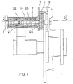
- the brake block 5 is fixed on the frame 3, which is mounted so as to be movable in the axial direction of its supporting tenons 17 to ensure a balanced distribution of the braking force applied on the brake disc via the brake blocks 4 and 5.
- the brake block 4 is attached at its middle to the pushing rod 7 by means of a pivot 6.
- the brake actuation lever 9 part of which is visible in the figure, is pulled at e.g. by means of a wire cable, the lever will turn on its pivot 10, thereby moving the pushing rod 7 attached to it by means of the pivot 8 and thus pressing the brake block 4, pivoted on the other end of the rod 7, against the brake disc 2.
- the brake block 4 now tends to move in the direction of rotation of the brake disc 2, so that when the vehicle is moving forward, i.e. in the direction indicated by the arrow in the figure, a force is exerted on the rod 7, pressing it sideways against the check block 14 and thus increasing the torsion of the brake actuation lever 9, thereby increasing the braking force.
- the brake actuation lever 9 is returned to its rest position by means of a spring 15.
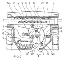
- the brake disc 2 will rotate in the opposite direction, i.e. the direction indicated by the arrow shown with a broken line.
- the brake block 4 is free to move in this direction because the pushing rod 7 can turn unobstructed until it reaches the limit of its range of movement. After reversal, the brake block 4 is returned to its normal position by a spring 16.
- the wear of the brake blocks is compensated for by means of a ratchet wheel mechanism 11 employing an eccentric arrangement, actuating the trunnion 10 of the brake actuation lever 9.
- the tooth discs 21 and 22 of the ratchet wheel 11 are attached to the frame 3 by means of bearings at their centres 20, and the two discs are fixedly joined by the trunnion 10 of the brake actuation lever 9 located between the upper 22 and the lower 21 tooth disc.
- the trunnion 10 is eccentrically positioned relative to the ratchet wheel axle 20.
- the tooth discs 21 and 22 are staggered relative to each other in such manner that the tip of a tooth on the lower disc 21 is aligned with the middle point of an indentation on the upper disc 22.
- each pair 12a and 12b are connected to each other by a slat 18, to which a pressure is applied by a spring 13 pressing the pair of pawls against the toothed quadrants 23a and 23b of the ratchet wheel 11 in such manner that each pawl in the pair is able to function independently of the other one.
- one of the pawls in each pair is longer than the other by an amount equal to half the distance between two successive teeth on a tooth disc 21, 22.
- the brake actuation lever 9 With wear of the brake blocks, the brake actuation lever 9 will turn through a greater angular distance and at the same time, by means of the pawls 12a, it will turn the ratchet wheel 11 so that, when one or both of the brake blocks 4 and 5 are worn to a certain degree, one of the retaining pawls 12b will be able to engage another tooth on the quadrant 23b, with the result that the brake actuation lever 9, being pivoted on the ratchet wheel 11, is brought closer to the brake disc 2.
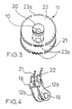
- the tooth discs 21 and 22 are not exactly round in form, the toothed quadrants 23a and 23b having slightly differing radial centres.
- the radial centre of the quadrant 23a which engages with the pawls 12a turning the wheel, is on the trunnion 10 of the brake actuation lever 9, whereas the radial centre of the quadrant 23b, which engages with the retaining pawls 12b, attached to the frame 3 with bearings.
Landscapes
- Engineering & Computer Science (AREA)
- General Engineering & Computer Science (AREA)
- Mechanical Engineering (AREA)
- Transportation (AREA)
- Physics & Mathematics (AREA)
- Fluid Mechanics (AREA)
- Braking Arrangements (AREA)
Claims (8)
Applications Claiming Priority (2)
| Application Number | Priority Date | Filing Date | Title |
|---|---|---|---|
| FI841268A FI72293C (fi) | 1984-03-29 | 1984-03-29 | Bromsanordning foer slaepvagn. |
| PCT/FI1985/000079 WO1987002108A1 (en) | 1984-03-29 | 1985-09-25 | Braking device for a trailer |
Publications (2)
| Publication Number | Publication Date |
|---|---|
| EP0247028A1 EP0247028A1 (de) | 1987-12-02 |
| EP0247028B1 true EP0247028B1 (de) | 1989-04-05 |
Family
ID=26157590
Family Applications (1)
| Application Number | Title | Priority Date | Filing Date |
|---|---|---|---|
| EP85904819A Expired EP0247028B1 (de) | 1984-03-29 | 1985-09-25 | Bremsanordnung für anhänger |
Country Status (4)
| Country | Link |
|---|---|
| EP (1) | EP0247028B1 (de) |
| DE (1) | DE3569277D1 (de) |
| FI (2) | FI72293C (de) |
| WO (1) | WO1987002108A1 (de) |
Families Citing this family (4)
| Publication number | Priority date | Publication date | Assignee | Title |
|---|---|---|---|---|
| WO1995010438A1 (en) * | 1993-10-12 | 1995-04-20 | Boris Georgievich Gadiev | Automatic clearance for vehicle brakes |
| GB2326449A (en) * | 1997-04-05 | 1998-12-23 | Peter Frederick Willmer | Over-run trailer brakes |
| ZA200406301B (en) * | 2003-08-06 | 2005-08-31 | Der Lingen Theophilus Wilhelm Van | Disc brake |
| PL384705A1 (pl) * | 2008-03-14 | 2009-09-28 | Debon Spółka Z Ograniczoną Odpowiedzialnością | Hamulec tarczowy najazdowy |
Family Cites Families (5)
| Publication number | Priority date | Publication date | Assignee | Title |
|---|---|---|---|---|
| US2850123A (en) * | 1956-05-11 | 1958-09-02 | Glyndwr L Davis | Brake adjusting apparatus |
| US3003589A (en) * | 1960-08-22 | 1961-10-10 | Azusa Engineering Inc | Vehicular brake |
| US3463274A (en) * | 1967-09-26 | 1969-08-26 | Kelsey Hayes Co | Disk brake assembly and mounting means therefor |
| US3690417A (en) * | 1971-01-28 | 1972-09-12 | Airheart Prod | Wear compensated, force multiplying disc brake |
| US4066154A (en) * | 1976-11-22 | 1978-01-03 | Amf Incorporated | Self-adjusting bike brake operating mechanism |
-
0
- FI FI841268A patent/FI841268A7/fi unknown
-
1984
- 1984-03-29 FI FI841268A patent/FI72293C/fi not_active IP Right Cessation
-
1985
- 1985-09-25 DE DE8585904819T patent/DE3569277D1/de not_active Expired
- 1985-09-25 EP EP85904819A patent/EP0247028B1/de not_active Expired
- 1985-09-25 WO PCT/FI1985/000079 patent/WO1987002108A1/en not_active Ceased
Also Published As
| Publication number | Publication date |
|---|---|
| DE3569277D1 (en) | 1989-05-11 |
| FI72293B (fi) | 1987-01-30 |
| FI72293C (fi) | 1987-05-11 |
| EP0247028A1 (de) | 1987-12-02 |
| FI841268A7 (fi) | 1985-09-30 |
| FI841268A0 (fi) | 1984-03-29 |
| WO1987002108A1 (en) | 1987-04-09 |
Similar Documents
| Publication | Publication Date | Title |
|---|---|---|
| US6336686B2 (en) | Modular disc brake and actuator level therefor | |
| EP1322871B1 (de) | Radbremsvorrichtung | |
| JP3538198B2 (ja) | 特にトラックおよびバスのためのディスクブレーキ自動調整式操作装置 | |
| HU181319B (en) | Brake lever for automatically adjusting drum brake | |
| US4928543A (en) | Electrically operated drum brake | |
| JPH08502578A (ja) | 機械的駆動ドラムブレーキ | |
| US20180038428A1 (en) | Brake actuator | |
| US3236336A (en) | Means for actuating a friction pad in a disc brake | |
| GB1493831A (en) | Brakes | |
| EP0247028B1 (de) | Bremsanordnung für anhänger | |
| US4006801A (en) | Automatic slack adjusters for vehicles | |
| US3111198A (en) | Automatic brake adjuster for spot-type, lever actuated disc brakes | |
| US4623046A (en) | Automatic adjuster for duo-servo internal shoe drum brakes | |
| US3625315A (en) | Braking control means | |
| US4585095A (en) | Actuating device for a disc brake | |
| US6206148B1 (en) | Drum brake with duo-actuation | |
| US3338355A (en) | Tread brake unit and slack adjuster therefor | |
| WO2006055988A1 (en) | Mechanical disc braking assembly | |
| US4161238A (en) | Self energizing brake assembly | |
| US4706785A (en) | Single point actuated self-adjusting brake mechanism in a vehicle driven by a cross-drive transmission | |
| EP1096166B1 (de) | Betätigungsvorrichtung für eine Kugel-Rampen- Bremse | |
| US3334707A (en) | Disc brake for rail vehicles | |
| EP1660361B1 (de) | Scheibenbremse | |
| EP0067287B1 (de) | Selbsttätige Bremsnachstellvorrichtung | |
| US6170243B1 (en) | Brake mechanism |
Legal Events
| Date | Code | Title | Description |
|---|---|---|---|
| PUAI | Public reference made under article 153(3) epc to a published international application that has entered the european phase |
Free format text: ORIGINAL CODE: 0009012 |
|
| AK | Designated contracting states |
Kind code of ref document: A1 Designated state(s): DE FR GB SE |
|
| 17P | Request for examination filed |
Effective date: 19870530 |
|
| RAP1 | Party data changed (applicant data changed or rights of an application transferred) |
Owner name: UKKO-TUOTTEET KY |
|
| RIN1 | Information on inventor provided before grant (corrected) |
Inventor name: SIMONEN, TENHO RAIMO JUHANI |
|
| 17Q | First examination report despatched |
Effective date: 19880901 |
|
| GRAA | (expected) grant |
Free format text: ORIGINAL CODE: 0009210 |
|
| AK | Designated contracting states |
Kind code of ref document: B1 Designated state(s): DE FR GB SE |
|
| REF | Corresponds to: |
Ref document number: 3569277 Country of ref document: DE Date of ref document: 19890511 |
|
| ET | Fr: translation filed | ||
| PLBE | No opposition filed within time limit |
Free format text: ORIGINAL CODE: 0009261 |
|
| STAA | Information on the status of an ep patent application or granted ep patent |
Free format text: STATUS: NO OPPOSITION FILED WITHIN TIME LIMIT |
|
| 26N | No opposition filed | ||
| PGFP | Annual fee paid to national office [announced via postgrant information from national office to epo] |
Ref country code: GB Payment date: 19900810 Year of fee payment: 6 |
|
| PGFP | Annual fee paid to national office [announced via postgrant information from national office to epo] |
Ref country code: SE Payment date: 19900920 Year of fee payment: 6 |
|
| PGFP | Annual fee paid to national office [announced via postgrant information from national office to epo] |
Ref country code: FR Payment date: 19900926 Year of fee payment: 6 |
|
| PGFP | Annual fee paid to national office [announced via postgrant information from national office to epo] |
Ref country code: DE Payment date: 19901130 Year of fee payment: 6 |
|
| PG25 | Lapsed in a contracting state [announced via postgrant information from national office to epo] |
Ref country code: GB Effective date: 19910925 |
|
| PG25 | Lapsed in a contracting state [announced via postgrant information from national office to epo] |
Ref country code: SE Effective date: 19910926 |
|
| GBPC | Gb: european patent ceased through non-payment of renewal fee | ||
| PG25 | Lapsed in a contracting state [announced via postgrant information from national office to epo] |
Ref country code: FR Effective date: 19920529 |
|
| PG25 | Lapsed in a contracting state [announced via postgrant information from national office to epo] |
Ref country code: DE Effective date: 19920602 |
|
| REG | Reference to a national code |
Ref country code: FR Ref legal event code: ST |
|
| EUG | Se: european patent has lapsed |
Ref document number: 85904819.1 Effective date: 19920408 |