EP0247009A2 - A combined veneer trimmer and adhesive spreader machine - Google Patents
A combined veneer trimmer and adhesive spreader machine Download PDFInfo
- Publication number
- EP0247009A2 EP0247009A2 EP87830181A EP87830181A EP0247009A2 EP 0247009 A2 EP0247009 A2 EP 0247009A2 EP 87830181 A EP87830181 A EP 87830181A EP 87830181 A EP87830181 A EP 87830181A EP 0247009 A2 EP0247009 A2 EP 0247009A2
- Authority
- EP
- European Patent Office
- Prior art keywords
- veneers
- rollers
- bed
- adhesive spreader
- adhesive
- Prior art date
- Legal status (The legal status is an assumption and is not a legal conclusion. Google has not performed a legal analysis and makes no representation as to the accuracy of the status listed.)
- Withdrawn
Links
- 239000000853 adhesive Substances 0.000 title claims abstract description 20
- 230000001070 adhesive effect Effects 0.000 title claims abstract description 20
- 238000006073 displacement reaction Methods 0.000 claims 1
- 238000000926 separation method Methods 0.000 claims 1
- 239000012530 fluid Substances 0.000 abstract 1
- 238000005520 cutting process Methods 0.000 description 3
- 238000009966 trimming Methods 0.000 description 2
- 230000007246 mechanism Effects 0.000 description 1
- 230000001105 regulatory effect Effects 0.000 description 1
Images


Classifications
-
- B—PERFORMING OPERATIONS; TRANSPORTING
- B27—WORKING OR PRESERVING WOOD OR SIMILAR MATERIAL; NAILING OR STAPLING MACHINES IN GENERAL
- B27L—REMOVING BARK OR VESTIGES OF BRANCHES; SPLITTING WOOD; MANUFACTURE OF VENEER, WOODEN STICKS, WOOD SHAVINGS, WOOD FIBRES OR WOOD POWDER
- B27L5/00—Manufacture of veneer ; Preparatory processing therefor
- B27L5/08—Severing sheets or segments from veneer strips; Shearing devices therefor; Making veneer blanks, e.g. trimming to size
-
- B—PERFORMING OPERATIONS; TRANSPORTING
- B27—WORKING OR PRESERVING WOOD OR SIMILAR MATERIAL; NAILING OR STAPLING MACHINES IN GENERAL
- B27D—WORKING VENEER OR PLYWOOD
- B27D1/00—Joining wood veneer with any material; Forming articles thereby; Preparatory processing of surfaces to be joined, e.g. scoring
- B27D1/10—Butting blanks of veneer; Joining same along edges; Preparatory processing of edges, e.g. cutting
-
- B—PERFORMING OPERATIONS; TRANSPORTING
- B27—WORKING OR PRESERVING WOOD OR SIMILAR MATERIAL; NAILING OR STAPLING MACHINES IN GENERAL
- B27G—ACCESSORY MACHINES OR APPARATUS FOR WORKING WOOD OR SIMILAR MATERIALS; TOOLS FOR WORKING WOOD OR SIMILAR MATERIALS; SAFETY DEVICES FOR WOOD WORKING MACHINES OR TOOLS
- B27G11/00—Applying adhesives or glue to surfaces of wood to be joined
Definitions
- the present invention relates to a machine for trimming at least one edge of a stack of veneers to prepare these for a correct edgewise connection.
- the object of the present invention is that of eliminating the above-indicated disadvantages by providing a trimmer/spreader machine for the treatment of stacks of veneers, which is able to hold the treated stack firmly and in such a way as to allow a perfect cutting along two opposite sides of the stack to trim opposite edges of the veneers with great accuracy.
- a combined veneer trimmer and adhesive spreader machine for the treatment of stacks of veneers, characterised in that it comprises a lower bed and an upper press over the facing surfaces of which pass corresponding reciprocable lower and upper conveyor belts; two parallel, longitudinally extending blades lying one on either side of the position occupied by a stack of veneers on the said lower bed, and a plurality of rollers the axes of which are substantially perpendicular to the general plane of the individual sheets of veneer on the stack thereof, operable to spread a layer of appropriate adhesive onto opposite edges of the veneers.
- a particular advantage of the present invention is that of providing a trimmer/spreader machine with which it is possible to obtain perfectly squared sheets of veneers, which sheets can therefore be correctly connected edgewise.
- Another advantage of the present invention is that of providing a trimmer/spreader which is functionally very reliable.
- the trimmer/spreader machine illustrated essentially comprises a movable bed 1, mounted on a base 2 and over which a conveyor belt 3 is slidable, this latter being driven to advance and retract by two rollers 4 and 5 over which respective ends of the conveyor belt 3 is wound.
- the rollers 4,5 are driven to rotate by corresponding geared motor units 6,7.
- a stack of veneers 7 to be trimmed is carried on the first conveyor belt 3.
- a second conveyor belt 8 also driven with reciprocating motion by pairs of rollers 9 and 10 which are themselves driven by corresponding geared motor units 11, which are carried on a press 13 suspended via actuating cylinders 14 from a cross beam 15.
- This latter also carries an upper blade carrier 17 by means of pivoted arms 16, the upper blade carrier 17 carrying a blade 18 and capable of translating downwardly along an inclined path under the action of a double acting cylinder 19.
- a similar lower blade carrier 20 with associated lower blade 21 is articulated to the base 2 by means of arms 22 and is displaceable upwardly at an angle by a further actuator cylinder 23.
- the upper blade 18 carried on the upper blade carrier 17 acts on one longitudinal edge of the stack 7 whilst the lower blade 21 carried on the lower blade carrier 20 acts on the opposite longitudinal edge of the stack.
- an adhesive-spreading apparatus operable to spread a layer of an appropriate adhesive onto the two opposite trimmed sides of the stack 7 of veneers.
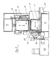
- This apparatus substantially comprises spreader rollers 25 and metering rollers 26 in contact with one another and mounted with their axes vertical on supports comprising, respectively, fixed supports 27 and movable supports 28 in such a way as to be able to adapt themselves to the width of the stack of veneers. They are shown in their position of closest approach in the plan view of Figure 3.
- the rotation of the rollers 25,26 which are supplied with adhesive from an appropriate reservoir 29 by means (not shown) is effected by means of a geared motor 31 and a flexible drive shaft 32. Beneath the rollers 20,26 is a collection vessel 30 which removes surplus adhesive.
- a lateral adjustment member 40 capable of acting on the pack of veneers to adjust its lateral position on the bed 1, and a guide 41 for guiding translation in the horizontal plane of the movable bed 1, such translation movements being effected by suitable mechanisms, generally indicated 42 driven by an appropriate geared motor 43 (see Figure 3).
Landscapes
- Life Sciences & Earth Sciences (AREA)
- Engineering & Computer Science (AREA)
- Wood Science & Technology (AREA)
- Forests & Forestry (AREA)
- Mechanical Engineering (AREA)
- Manufacturing & Machinery (AREA)
- Veneer Processing And Manufacture Of Plywood (AREA)
Abstract
A combined veneer trimmer and adhesive spreader machine has a bed (1) for supporting packs of veneers, over which bed moves a lower reciprocable conveyor belt (3) which can be driven in synchronism with an upper reciprocable conveyor belt (8) carried on a press member (13) displaceable vertically and carried on a cross beam (15). Opposite longitudinal edges of the veneers in a stack (7) held between the upper and lower reciprocable conveyor belts are trimmed by respective opposite blades (18,21) each carried by a respective blade carrier (17,20) which can be displaced along an inclined path under the action of a respective double acting fluid pressure cylinder (19,23) so that the stack of veneers is cut whilst in horizontal motion without warping thereof due to the firm grip applied by the upper and lower reciprocable conveyor belts and the fact that the path of the cutter blades is inclined.
Downstream of the upper and lower reciprocable conveyor belts there are provided vertical axis driven rollers (25,26) capable of spreading a layer of an adhesive on the opposite cut edges of the veneers themselves.
Description
- The present invention relates to a machine for trimming at least one edge of a stack of veneers to prepare these for a correct edgewise connection.
- Known machines for performing this operation are equipped in such a way as to be able automatically to trim stacks of sheets of veneers along opposite edges of the sheets themselves. With such known cutting or trimming machines of conventional type, however, it can easily happen that difficulties arise in making the cuts which define the rectilinear opposite edges of the sheets, which edges have to be perfectly straight and parallel to fit together when the veneers are subsequently joined edge-to-edge. This arises because, during the cutting operation, the stack of veneers is not adequately restrained and therefore the various sheets can be subjected to unwanted warping phenomena. Consequently the edges may not be straight or parallel and therefore may not be able to fit together edge-to-edge in a proper relationship.
- This connection, consequently, must necessarily be performed by overlapping the edges of the sheets with preliminary operations on the faces to conveniently taper the corresponding edges of the sheets.
- The object of the present invention is that of eliminating the above-indicated disadvantages by providing a trimmer/spreader machine for the treatment of stacks of veneers, which is able to hold the treated stack firmly and in such a way as to allow a perfect cutting along two opposite sides of the stack to trim opposite edges of the veneers with great accuracy.
- According to the present invention, therefore, there is provided a combined veneer trimmer and adhesive spreader machine for the treatment of stacks of veneers, characterised in that it comprises a lower bed and an upper press over the facing surfaces of which pass corresponding reciprocable lower and upper conveyor belts; two parallel, longitudinally extending blades lying one on either side of the position occupied by a stack of veneers on the said lower bed, and a plurality of rollers the axes of which are substantially perpendicular to the general plane of the individual sheets of veneer on the stack thereof, operable to spread a layer of appropriate adhesive onto opposite edges of the veneers.
- A particular advantage of the present invention is that of providing a trimmer/spreader machine with which it is possible to obtain perfectly squared sheets of veneers, which sheets can therefore be correctly connected edgewise.
- Another advantage of the present invention is that of providing a trimmer/spreader which is functionally very reliable.
- One embodiment of the invention will now be more particularly described, by way of example, with reference to the accompanying drawings, in which:
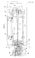
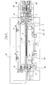
- Figure 1 is a schematic side view of a machine formed as an embodiment of the invention;
- Figure 2 is a further side view of the embodiment of Figure 1, seen from the opposite side;
- Figure 3 is a plan view of the embodiment of Figures 1 and 2;
- Figure 4 is a front view of the machine of the invention; and
- Figure 5 is a rear view of the machine of the invention.
- Referring now to the drawings, the trimmer/spreader machine illustrated essentially comprises a movable bed 1, mounted on a
base 2 and over which aconveyor belt 3 is slidable, this latter being driven to advance and retract by tworollers 4 and 5 over which respective ends of theconveyor belt 3 is wound. Therollers 4,5 are driven to rotate by corresponding gearedmotor units - A stack of
veneers 7 to be trimmed is carried on thefirst conveyor belt 3. Above thefirst conveyor belt 3 is asecond conveyor belt 8, also driven with reciprocating motion by pairs ofrollers 9 and 10 which are themselves driven by corresponding gearedmotor units 11, which are carried on apress 13 suspended via actuatingcylinders 14 from across beam 15. This latter also carries anupper blade carrier 17 by means ofpivoted arms 16, theupper blade carrier 17 carrying ablade 18 and capable of translating downwardly along an inclined path under the action of a double actingcylinder 19. - A similar
lower blade carrier 20 with associatedlower blade 21 is articulated to thebase 2 by means ofarms 22 and is displaceable upwardly at an angle by afurther actuator cylinder 23. As can be seen in Figure 5 theupper blade 18 carried on theupper blade carrier 17 acts on one longitudinal edge of thestack 7 whilst thelower blade 21 carried on thelower blade carrier 20 acts on the opposite longitudinal edge of the stack. - Downstream of the
conveyor belts stack 7 of veneers. This apparatus substantially comprisesspreader rollers 25 andmetering rollers 26 in contact with one another and mounted with their axes vertical on supports comprising, respectively, fixedsupports 27 andmovable supports 28 in such a way as to be able to adapt themselves to the width of the stack of veneers. They are shown in their position of closest approach in the plan view of Figure 3. The rotation of therollers appropriate reservoir 29 by means (not shown) is effected by means of a gearedmotor 31 and aflexible drive shaft 32. Beneath therollers collection vessel 30 which removes surplus adhesive. - Above the movable bed 1 and beneath the
press 13 arerespective guides rollers 35 operable to appropriately compress the stack of veneers. Downstream of the spreading apparatus there is provided a further pair of conveyor belts, respectively an uppercontinuous belt 36 and a lowercontinuous belt 37 driven by correspondinggeared motors 38 and provided withappropriate devices 39 for regulating their tension. - In Figure 5 can be seen a
lateral adjustment member 40 capable of acting on the pack of veneers to adjust its lateral position on the bed 1, and aguide 41 for guiding translation in the horizontal plane of the movable bed 1, such translation movements being effected by suitable mechanisms, generally indicated 42 driven by an appropriate geared motor 43 (see Figure 3).
Claims (6)
1. A combined veneer trimmer and adhesive spreader machine for the treatment of stacks (7) of veneers, characterised in that it comprises a lower bed (1) and an upper press (13) over the facing surfaces of which pass corresponding reciprocable lower and upper conveyor belts (3,8); two parallel, longitudinally extending blades (18,21) lying one on either side of the position occupied by a stack (7) of veneers on the said lower bed (1), and a plurality of adhesive spreader rollers (25,26) the axes of which are substantially perpendicular to the general plane of the individual sheets of veneer on the stack (7) thereof, operable to spread a layer of adhesive onto opposite edges of the veneers.
2. A combined veneer trimmer and adhesive spreader machine according to Claim 1, characterised in that the said bed (1) is mounted on a base (2) and is displaceable laterally with respect to the said bed (1), the said lower reciprocable conveyor belt (3) being wound at each end over lower rollers (4,5) driven by corresponding geared motor units (6) and the said upper reciprocal conveyor belt (8) being wound at each end over upper rollers (9,10) driven by corresponding geared motor units (11,12).
3. A combined veneer trimmer and adhesive spreader machine according to Claim 2, characterised in that the said upper reciprocable conveyor belt (8) is supported by means of the said upper rollers (9,10) from the upper press (13) which latter is supported by actuator cylinders (14) on a beam (15) on which are articulated a plurality of arms (16) carrying an upper blade carrier (17) on which a horizontal upper blade (18) is supported, the upper blade carrier (17) being guided for movement along a path inclined at an angle to the said beam (15) by a double acting cylinder (19); a corresponding lower blade carrier (20) and associated blade (21) being articulated to the base (2) by means of arms (22) and displaceable along an upwardly inclined path by a lower double-acting cylinder (23).
4. A combined veneer trimmer and adhesive spreader machine according to any preceding Claim, characterised in that the adhesive spreader rollers are located downstream of the said reciprocable conveyor belts (3,8) and there are provided cooperating metering rollers (26) in contact with respective adhesive spreader rollers (25) and also mounted with their axes vertical, at least one pair of rollers being carried on movable supports (34,35) so as to be able to adapt the separation of the adhesive spreader rollers to the width of the stack (7) of veneers.
5. A combined veneer trimmer and adhesive spreader machine according to any preceding Claim, characterised in that downstream of the said adhesive spreader rollers (25,26) there is provided a pair of continuous conveyor belts (36,37) respectively an upper belt (36) and a lower belt (37) driven by corresponding geared motor units (38) and provided with tension regulation devices (39).
6. A combined veneer trimmer and adhesive spreader machine according to any of Claims 2 to 5, characterised in that the said machine includes an adjustment member (40) capable of acting laterally on the pack (7) of veneers on the said bed (1), a guide (41) for guiding the said movable bed (1) in the horizontal plane and a geared motor unit (29) for effecting lateral displacement of the said bed.
Applications Claiming Priority (3)
| Application Number | Priority Date | Filing Date | Title |
|---|---|---|---|
| IT2052286 | 1986-05-22 | ||
| IT20522/86A IT1188714B (en) | 1986-05-22 | 1986-05-22 | Combined veneer trimmer and adhesive spreader machine |
| DK363787A DK363787A (en) | 1986-05-22 | 1987-07-13 | COMBINED FINISHER AND ADHESIVE APPLICATION MACHINE |
Publications (1)
| Publication Number | Publication Date |
|---|---|
| EP0247009A2 true EP0247009A2 (en) | 1987-11-25 |
Family
ID=26067147
Family Applications (1)
| Application Number | Title | Priority Date | Filing Date |
|---|---|---|---|
| EP87830181A Withdrawn EP0247009A2 (en) | 1986-05-22 | 1987-05-14 | A combined veneer trimmer and adhesive spreader machine |
Country Status (3)
| Country | Link |
|---|---|
| US (1) | US4763704A (en) |
| EP (1) | EP0247009A2 (en) |
| DK (1) | DK363787A (en) |
Cited By (1)
| Publication number | Priority date | Publication date | Assignee | Title |
|---|---|---|---|---|
| CN110722647A (en) * | 2019-11-29 | 2020-01-24 | 湖南易红堂家具制造有限公司 | Feeding device for splicing furniture boards |
Family Cites Families (4)
| Publication number | Priority date | Publication date | Assignee | Title |
|---|---|---|---|---|
| US691267A (en) * | 1901-02-06 | 1902-01-14 | Richard S Hill | Machine for jointing and sizing lumber. |
| SU379386A1 (en) * | 1971-11-16 | 1973-04-20 | Э. К. тко , Ю. Д. Любенко Гомельское производственное деревообрабатывающее объединение | SEMI-AUTOMATIC LINE FOR STRENGTHENING THE CROP-SHEET DETAILS |
| SU844290A1 (en) * | 1980-01-10 | 1981-07-07 | Центральный Научно-Исследовательскийинститут Фанеры | Apparatus for forming veneer stack |
| SU895662A1 (en) * | 1980-08-14 | 1982-01-07 | за витель И tСОЮЗНАЯ тштп iLAS..4teKAs Б-Ь/;иОГЕг.А П И С А ЗОБРЕТЕНИЯ К АВТОРСКОМУ СВИДЕТЕЛЬСТВУ (61)Дополнительное к авт. свид-ву - (22)За влено 14.08.80 | Apparatus for bonding together veneer plates |
-
1987
- 1987-05-14 EP EP87830181A patent/EP0247009A2/en not_active Withdrawn
- 1987-05-15 US US07/050,759 patent/US4763704A/en not_active Expired - Fee Related
- 1987-07-13 DK DK363787A patent/DK363787A/en not_active Application Discontinuation
Cited By (1)
| Publication number | Priority date | Publication date | Assignee | Title |
|---|---|---|---|---|
| CN110722647A (en) * | 2019-11-29 | 2020-01-24 | 湖南易红堂家具制造有限公司 | Feeding device for splicing furniture boards |
Also Published As
| Publication number | Publication date |
|---|---|
| DK363787D0 (en) | 1987-07-13 |
| DK363787A (en) | 1989-01-14 |
| US4763704A (en) | 1988-08-16 |
Similar Documents
| Publication | Publication Date | Title |
|---|---|---|
| US4484501A (en) | Apparatus for cutting and trimming paper sheets or the like | |
| CA1066990A (en) | Band saw machine | |
| EP3085501B1 (en) | Apparatus for performing cutting operation of open formatedges of a printproduct | |
| EP1491303B1 (en) | Method and apparatus for trimming printed products | |
| CN217263659U (en) | Automatic clamping and cutting device | |
| US20040112195A1 (en) | Book trimming machine with combined-motion blades | |
| US4300427A (en) | Three-knife trimmer | |
| US6899003B1 (en) | Rotary cutting machine for corrugated cardboard plate | |
| EP0247009A2 (en) | A combined veneer trimmer and adhesive spreader machine | |
| EP1579966B1 (en) | Fabric cutting system | |
| US4665599A (en) | Machine for the production of venetian blinds | |
| US4576369A (en) | Method in producing stitched printed matters and feeder for working the method | |
| EP0206374A2 (en) | An apparatus for packing a row of lids and the completed package | |
| US3998252A (en) | Wood slicing apparatus | |
| US5390716A (en) | Device for the slicing production of boards | |
| US3815458A (en) | Machine for cutting non-rigid materials | |
| US5211090A (en) | Method of and apparatus for shaping the corners of stacked sheet material | |
| US3667522A (en) | Slicing apparatus | |
| EP4188687B1 (en) | Machine for wrapping already formed boxes with a covering sheet | |
| US3329053A (en) | Machine for splitting apart two-on siamese twin books | |
| CN212286092U (en) | Bilateral device is cut to panel of composite sheet production line | |
| CN208133093U (en) | A kind of fervent mechanism | |
| CN218699239U (en) | Cutting device | |
| CN219650659U (en) | Paper box cutting device of environment-friendly packaging box | |
| KR102826704B1 (en) | Jig for fixing cuttings of a cutter |
Legal Events
| Date | Code | Title | Description |
|---|---|---|---|
| PUAI | Public reference made under article 153(3) epc to a published international application that has entered the european phase |
Free format text: ORIGINAL CODE: 0009012 |
|
| AK | Designated contracting states |
Kind code of ref document: A2 Designated state(s): BE CH DE ES FR LI |
|
| STAA | Information on the status of an ep patent application or granted ep patent |
Free format text: STATUS: THE APPLICATION HAS BEEN WITHDRAWN |
|
| 18W | Application withdrawn |
Withdrawal date: 19890605 |
|
| R18W | Application withdrawn (corrected) |
Effective date: 19890605 |
|
| RIN1 | Information on inventor provided before grant (corrected) |
Inventor name: PROVENZI, ENRICO |