EP0246822A2 - Schneidvorrichtung zum Garnieren von Früchten - Google Patents
Schneidvorrichtung zum Garnieren von Früchten Download PDFInfo
- Publication number
- EP0246822A2 EP0246822A2 EP87304328A EP87304328A EP0246822A2 EP 0246822 A2 EP0246822 A2 EP 0246822A2 EP 87304328 A EP87304328 A EP 87304328A EP 87304328 A EP87304328 A EP 87304328A EP 0246822 A2 EP0246822 A2 EP 0246822A2
- Authority
- EP
- European Patent Office
- Prior art keywords
- cutter
- melons
- melon
- base
- support member
- Prior art date
- Legal status (The legal status is an assumption and is not a legal conclusion. Google has not performed a legal analysis and makes no representation as to the accuracy of the status listed.)
- Withdrawn
Links
Images

Classifications
-
- B—PERFORMING OPERATIONS; TRANSPORTING
- B26—HAND CUTTING TOOLS; CUTTING; SEVERING
- B26D—CUTTING; DETAILS COMMON TO MACHINES FOR PERFORATING, PUNCHING, CUTTING-OUT, STAMPING-OUT OR SEVERING
- B26D3/00—Cutting work characterised by the nature of the cut made; Apparatus therefor
- B26D3/24—Cutting work characterised by the nature of the cut made; Apparatus therefor to obtain segments other than slices, e.g. cutting pies
-
- B—PERFORMING OPERATIONS; TRANSPORTING
- B26—HAND CUTTING TOOLS; CUTTING; SEVERING
- B26D—CUTTING; DETAILS COMMON TO MACHINES FOR PERFORATING, PUNCHING, CUTTING-OUT, STAMPING-OUT OR SEVERING
- B26D1/00—Cutting through work characterised by the nature or movement of the cutting member or particular materials not otherwise provided for; Apparatus or machines therefor; Cutting members therefor
- B26D1/0006—Cutting members therefor
- B26D2001/006—Cutting members therefor the cutting blade having a special shape, e.g. a special outline, serrations
Definitions
- Cantaloupes, honeydew melons, etc. are conventionally severed continuously and in an annular cut around midsections in a fancy cutting operation in supermarkets, catering operations, etc.
- the fancy cut is usually a serration with the melon being thus split into half sections, the seeds and other material in the central portion removed and the melon thereafter filled with grapes, portions of other melons, and various other colorful fruit in a pleasing and appetizing display.
- the melons bring a premium price and supermarkets, caterers, etc. would be more inclined to employ a fancy cutting operation except for the extremely tedious and time consuming methods presently used.
- Either a simple straight knife or perhaps a knife with a "V" shaped cross section is employed and the continuous cut around the mid section of the melon is accomplished incrementally in small stabbing type cuts.
- a device for effecting continuous fancy cuts such as serrations around melons and the like comprises an elongated substantially linear base and support member.
- An elongated generally linear cutter extends longitudinally and is supported on said base and support member with upper edge portions of the cutter being at least substantially continuous longitudinally and adapted to sever the skin of melons and the like.
- the shape of the cutter when viewed from above is such as to provide the desired type or design of preselected continuous fancy cuts around melons and the like and, preferably, the shape of the cutter takes a conventional saw-tooth configuration or serration.
- the base and support means extend laterally and at least slightly beyond the cutter at each side thereof so as to engage and support a melon which is rolled along the cutter with a slight downward manual pressure applied atop the melon.
- the cutter serves to progressively sever the skin of the melon in a continuous annular area around the same and provides the desired fancy cut.
- the height of the cutter relative to that portion of the base and support member which engages the melon is such that the melon is further and simultaneously severed to a desired depth beneath the skin where by to permit ready separation of the melon into half sections.
- the base and support member is preferably provided with a generally trough-like cross sectional configuration with opposite portions thereof extending upwardly and outwardly at gradual angles of inclination, approximately thirty degrees (30 ) being presently preferred.
- the melons may be rolled along the top of the cutter in a linear or straight line manner and the tendency of the trough is to maintain the melon in straight line or linear movement during revolution of the same.
- the angles of inclination mentioned the foregoing tendency toward straight line revolution is achieved with melons of varying dimension.
- the vertical dimension or height of the cutter relative to the base and support member, and more particularly, the inclined opposite portions thereof is such as to provide for the desired depth of cut with melons of various size or dimension. That is, the skin of the melon is effectively severed and the depth of the cut is sufficient to provide for the ready separation of the melon into the desired half-section configuration.
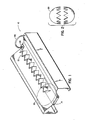
- the melon cutting device of the present invention includes an elongated substantially linear base and support member which is indicated generally at 10 and which carries an elongated upstanding linear cutter indicated generally at 12.
- the base and support member 10 may vary widely in construction but is preferivelyably of a trough-like configuration in cross section as best illustrated in Fig. 4.
- a generally flat central portion thereof at 14 serves as a support for the cutter 12.
- the central portion 14 has opposite side portions 16, 16 associated therewith and which are inclined upwardly and outwardly with respect thereto.
- the opposite side portions 16, 16 are inclined upwardly and outwardly from the horizontal at approximately thirty degrees (30 ).
- Vertical side sections of the base and support member at 18, 18 support the central portion 14 and the inclined portions 16, 16 and each such side member has a short inwardly extending flange 20 carrying an anti-skid member 22 which may be of rubber or the like.
- the central portion 14 is made separately from the opposite side portions 16, 16 of the base and support member and the base and support member has a central section 24 upon which the central portion 14 rests.
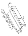
- two short sidewalls 26, 26 confine the member 14 laterally and it may be conveniently assembled and disassembled relative to the remaining portion of the base and support member in a relative endwise movement of the elements. That is, the portion 14 carrying the cutter 12 can be removed in an endwise sliding movement for cleansing of the cutter or for other purposes and may thereafter be readily replaced in the operative position shown in Figs. 1 and 4.
- a quick connect and disconnect means is provided for securing the central portion 14 and the cutter 12 in assembled position.
- a small bracket takes a generally U shape at 28 and is secured at one end of the support portion 24 beneath the central portion 14.
- An upper arm 30 of the small U shaped member 28 has an appropriate opening 32 for receiving a lock pin 34, the latter being entered vertically downwardly through the opening 32 and extending also through a similar opening 36 in an end portion of the central portion 14 of the base and support member.
- a connecting cord 38 carries the pin 34 at one end thereof and is secured at 40 to one of the side portions 16 of the base and support member to prevent loss or displacement of the pin 34.
- FIG. 7 for a clear illustration of the manner in which the several parts of the device may be disassembled on disengagement of the pin 34. It is of course understood that the central portion 14 and the cutter 12 are shown above the base and support member 10 but this positioning of the member is subsequent to the removal of the same from the base and support member 10 with the member 14 first being moved in an endwise direction at least a sufficient distance to disengage the member from the U-shaped bracket member 28.
- the cutter 12 which is disposed atop and supported by the central portion 14 of the base and support member provides a serration or other fancy cut around a midsection of a melon or the like as the latter is rolled or revolved therealong in a substantially straight line or in linear movement thereover.
- the hands of the user are positioned atop the melon and the melon is progressively rolled along in a simple, rapid and efficient cutting operation.
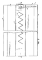
- the cutter 12 takes a conventional saw-tooth configuration viewed from above but it will of course be apparent that various other configurations may be provided such as sinusoidal, etc.
- the number of saw-tooth configurations may vary as desired from the number shown to 20 or more and it will be noted that the device shown has the cutter blade spaced from the end of the member 14 at a left hand or entry end thereof. That is, a melon may be placed as shown at 39 at the entry or loading end of the cutter and it may facilitate the loading and/or the initial cutting operation to have a short blank section as shown prior to the beginning of the cutting section.
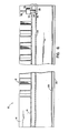
- the height of the upstanding cutter is also important and is established in relation to the base and support member so as to provide for the proper cutting of the melon. That is, the base and support member is provided with lateral extending portions at least slightly beyond and at each side of the cutter and as shown the portions 16, 16 extend a substantial distance beyond the cutter. In Fig. 4 it will be apparent that the position of the lower portion of the melon as indicated by the three broken lines 41, 42 and 44 is established by the side portions 16, 16. Thus, melons of varying size or dimension can be accomodated and in each instance, the relative height of the cutter 12 and the side portion 16, 16 will determine the depth of cut.
- the height of the blade is established relative to such flat portion.
- the depth of cut should be such that the skin of the melon is severed and the cut is of a sufficient depth therebeyond to provide for the ready separation of the melon into half sections as illustrated in Fig. 3, a melon being illustrated therein at the completion of a cutting operation.
- the height of the cutter should be at least one half (1/2) inch and the present cutter is approximately one (1) inch high with the inclined portions 16, 16 established at approximately thirty degrees (30 ) from the horizontal as mentioned above. Excellent results have been achieved with these dimensional and angular relationships.
- Melons of varying size may be placed at the entry end of the device sequentially, rapidly rolled along the length of the cutter with the trough guiding and urging the melons toward a straight line progression in their rolling or revolving movement and efficient cutting around the midsections of the melons results. Cuting time is reduced to a mere fraction of the cutting time involved with the prior techniques.
Landscapes
- Life Sciences & Earth Sciences (AREA)
- Forests & Forestry (AREA)
- Engineering & Computer Science (AREA)
- Mechanical Engineering (AREA)
- Food-Manufacturing Devices (AREA)
- Confectionery (AREA)
- Manufacturing And Processing Devices For Dough (AREA)
- Knives (AREA)
Applications Claiming Priority (2)
| Application Number | Priority Date | Filing Date | Title |
|---|---|---|---|
| US86816286A | 1986-05-22 | 1986-05-22 | |
| US868162 | 1997-06-02 |
Publications (2)
| Publication Number | Publication Date |
|---|---|
| EP0246822A2 true EP0246822A2 (de) | 1987-11-25 |
| EP0246822A3 EP0246822A3 (de) | 1990-02-07 |
Family
ID=25351177
Family Applications (1)
| Application Number | Title | Priority Date | Filing Date |
|---|---|---|---|
| EP87304328A Withdrawn EP0246822A3 (de) | 1986-05-22 | 1987-05-15 | Schneidvorrichtung zum Garnieren von Früchten |
Country Status (3)
| Country | Link |
|---|---|
| EP (1) | EP0246822A3 (de) |
| JP (1) | JPS62298390A (de) |
| CA (1) | CA1275228C (de) |
Family Cites Families (3)
| Publication number | Priority date | Publication date | Assignee | Title |
|---|---|---|---|---|
| US1924392A (en) * | 1931-07-08 | 1933-08-29 | H W Gehr | Fruit cutting machine |
| US2390700A (en) * | 1944-10-23 | 1945-12-11 | Phyllis K Fellner | Flexible band knife |
| US4457070A (en) * | 1982-09-07 | 1984-07-03 | Frederick Reeves | Fruit crowner |
-
1987
- 1987-05-15 EP EP87304328A patent/EP0246822A3/de not_active Withdrawn
- 1987-05-21 CA CA000537618A patent/CA1275228C/en not_active Expired - Fee Related
- 1987-05-22 JP JP12564887A patent/JPS62298390A/ja active Pending
Also Published As
| Publication number | Publication date |
|---|---|
| JPS62298390A (ja) | 1987-12-25 |
| CA1275228C (en) | 1990-10-16 |
| EP0246822A3 (de) | 1990-02-07 |
Similar Documents
| Publication | Publication Date | Title |
|---|---|---|
| US5431078A (en) | Apparatus for slicing a food article | |
| US4207653A (en) | Automatic wing cutting apparatus | |
| EP0271689B1 (de) | Gerät zum Schneiden von Pilzen in Scheiben | |
| US5557998A (en) | Bagel coring apparatus | |
| US4948106A (en) | Food cutting apparatus | |
| US4606263A (en) | Apparatus for peeling pineapples | |
| US4832045A (en) | Biopsy instrument | |
| US5533442A (en) | Avocado peeler and slicer | |
| US5361666A (en) | Bagel slicer | |
| CA2102600A1 (en) | Method and apparatus for helical food product | |
| US6484627B1 (en) | Skewer assembly for supporting a boneless cut of meat on a spiral meat slicer | |
| US4811642A (en) | Kitchen guillotine | |
| US4885842A (en) | Guard and guide for corn cutters | |
| US4779504A (en) | Device for fancy cutting melons and the like | |
| US3961418A (en) | Lemon peeler | |
| US4114265A (en) | Cake cutter and server | |
| JPH0337907B2 (de) | ||
| US6206356B1 (en) | Tray for holding food | |
| US4592113A (en) | Fish fileting knife | |
| US4320680A (en) | Fruit cutter | |
| US5033193A (en) | Bagel scooper | |
| US4449297A (en) | Clipping apparatus | |
| EP0246822A2 (de) | Schneidvorrichtung zum Garnieren von Früchten | |
| US6199283B1 (en) | Implement for holding and/or coring vegetables and/or fruits during preparation of the same | |
| US4937938A (en) | Egg slicers |
Legal Events
| Date | Code | Title | Description |
|---|---|---|---|
| PUAI | Public reference made under article 153(3) epc to a published international application that has entered the european phase |
Free format text: ORIGINAL CODE: 0009012 |
|
| AK | Designated contracting states |
Kind code of ref document: A2 Designated state(s): AT BE CH DE ES FR GB GR IT LI LU NL SE |
|
| PUAL | Search report despatched |
Free format text: ORIGINAL CODE: 0009013 |
|
| AK | Designated contracting states |
Kind code of ref document: A3 Designated state(s): AT BE CH DE ES FR GB GR IT LI LU NL SE |
|
| 17P | Request for examination filed |
Effective date: 19900228 |
|
| 17Q | First examination report despatched |
Effective date: 19910426 |
|
| STAA | Information on the status of an ep patent application or granted ep patent |
Free format text: STATUS: THE APPLICATION IS DEEMED TO BE WITHDRAWN |
|
| 18D | Application deemed to be withdrawn |
Effective date: 19911107 |
|
| RIN1 | Information on inventor provided before grant (corrected) |
Inventor name: MURPHY, ROBERT W. Inventor name: OUELLETTE, MARK L. |