EP0246790B2 - Vehicle braking system - Google Patents
Vehicle braking system Download PDFInfo
- Publication number
- EP0246790B2 EP0246790B2 EP87304148A EP87304148A EP0246790B2 EP 0246790 B2 EP0246790 B2 EP 0246790B2 EP 87304148 A EP87304148 A EP 87304148A EP 87304148 A EP87304148 A EP 87304148A EP 0246790 B2 EP0246790 B2 EP 0246790B2
- Authority
- EP
- European Patent Office
- Prior art keywords
- vehicle
- load
- braking
- axle
- weight
- Prior art date
- Legal status (The legal status is an assumption and is not a legal conclusion. Google has not performed a legal analysis and makes no representation as to the accuracy of the status listed.)
- Expired - Lifetime
Links
Images

Classifications
-
- B—PERFORMING OPERATIONS; TRANSPORTING
- B60—VEHICLES IN GENERAL
- B60T—VEHICLE BRAKE CONTROL SYSTEMS OR PARTS THEREOF; BRAKE CONTROL SYSTEMS OR PARTS THEREOF, IN GENERAL; ARRANGEMENT OF BRAKING ELEMENTS ON VEHICLES IN GENERAL; PORTABLE DEVICES FOR PREVENTING UNWANTED MOVEMENT OF VEHICLES; VEHICLE MODIFICATIONS TO FACILITATE COOLING OF BRAKES
- B60T8/00—Arrangements for adjusting wheel-braking force to meet varying vehicular or ground-surface conditions, e.g. limiting or varying distribution of braking force
- B60T8/26—Arrangements for adjusting wheel-braking force to meet varying vehicular or ground-surface conditions, e.g. limiting or varying distribution of braking force characterised by producing differential braking between front and rear wheels
- B60T8/266—Arrangements for adjusting wheel-braking force to meet varying vehicular or ground-surface conditions, e.g. limiting or varying distribution of braking force characterised by producing differential braking between front and rear wheels using valves or actuators with external control means
-
- B—PERFORMING OPERATIONS; TRANSPORTING
- B60—VEHICLES IN GENERAL
- B60T—VEHICLE BRAKE CONTROL SYSTEMS OR PARTS THEREOF; BRAKE CONTROL SYSTEMS OR PARTS THEREOF, IN GENERAL; ARRANGEMENT OF BRAKING ELEMENTS ON VEHICLES IN GENERAL; PORTABLE DEVICES FOR PREVENTING UNWANTED MOVEMENT OF VEHICLES; VEHICLE MODIFICATIONS TO FACILITATE COOLING OF BRAKES
- B60T8/00—Arrangements for adjusting wheel-braking force to meet varying vehicular or ground-surface conditions, e.g. limiting or varying distribution of braking force
- B60T8/17—Using electrical or electronic regulation means to control braking
- B60T8/1701—Braking or traction control means specially adapted for particular types of vehicles
- B60T8/1708—Braking or traction control means specially adapted for particular types of vehicles for lorries or tractor-trailer combinations
Definitions
- the present invention relates to vehicle braking systems of the electronically compensated type wherein, instead of the conventional hydraulic or pneumatic control system operating between the foot pedal and the brake actuators, the analysis of data concerning braking parameters, brake demand, vehicle loading, brake efficiency and the like is performed electronically and the brake actuators are controlled electronically in accordance with such analysis.
- the main sources of braking parameter change are measured and the pressure demands to inner closed loop pressure systems are adjusted by outer open loops to compensate for said parameter changes.
- One of the basic parameters which is measured in such systems is the vehicle loading (axle loads). It is with the method of determining the vehicle loading that the present invention is concerned.
- axle load measurements are made deliberately to have a long time constant so as to be assured of a good average load figure which has been established during the recent normal (non-braking) operation of the vehicle.
- the main sources of braking system disturbance in practice are vehicle load and operating gradient, both of which can change suddenly, and brake deterioration which is much more gradual.
- the sudden changes require compensation by corresponding sudden corrections whilst slow changes can be countered by a gradual adaptation over a time period which can extend into days or weeks depending on vehicle usage.
- a foot pedal transducer In a compensated braking system, a foot pedal transducer generates a first signal indicating the braking level desired by the driver and additional sensors measure the vehicle axle loads and the operating gradient.
- the system makes appropriate open loop corrections to the brake pressure demands being interpreted from the driver pedal input with the aim of restoring the vehicle deceleration to a level which is in proportion to the driver's demand.
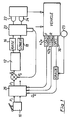
- FIG. 1 there is shown a pressure control loop taking an input Pi from a brake pedal transducer 10 which is used to provide a pressure error signal Pe by comparison of the input Pi with a pressure transducer output signal Po, this pressure error Pe forming the input to a pressure controller 12 which generates an output signal which causes the pressure developed by an electro-pneumatic or electro-hydraulic converter to change in a direction such as to reduce the amplitude of the pressure error Pe.
- Such a pressure controller 12 depends upon the type of converter employed. Two such converter principles are well known, namely an analogue system in which a valve is employed with pressure output developed porportional to solenoid current and a digital system (as shown) in which a pair of simpler solenoid valves 16,18 is employed to raise or lower a control chamber pressure by selective energisation.
- One form of pneumatic converter employs a relay valve 20 which responds to this control chamber pressure and which re-balances into the closed condition when the brake pressures in the left and right brake actuators 22,24 become equal to this control pressure.
- a relay valve 20 which responds to this control chamber pressure and which re-balances into the closed condition when the brake pressures in the left and right brake actuators 22,24 become equal to this control pressure.
- Such a valve has an advantage in that the control chamber pressure responds rapidly to valve opening, giving a fast control loop which is accurate and responsive.
- the compensated system of Fig.1 comprises a number of closed loop controllers (only one shown in Fig.1) which are separate for each axle or for each wheel and which are supplied with pressure demands by a braking correction sub-system 26 such that front and rear systems may receive different pressure demands for equal braking inputs.
- One principal disturbance to braking is caused by gradient and this can be sensed by a comparison between deceleration as sensed by a vehicle decelerometer and similar figures generated from speeds sensed by sensors 23 at the vehicle wheels and differentiated electronically after being combined to form a vehicle reference signal in a manner which is well known in anti-lock systems.
- the gradient figure generated is a deceleration error DE with a sign which indicates uphill or downhill and which can be added directly to braking demand in the sub-system 26 to achieve appropriate correction of the demand signal Pi.
- Another basic parameter which disturbs the braking performance is the vehicle loading and it is known to take axle load readings, generated by suitable transducers on the vehicle, and to use these as correction inputs to the sub-system 26 for modifying the brake demand signals Pi.
- This is achieved by the use of a (preferably digital) multiplier which forms a suitably scaled product of pedal input demand and axle load measurement to form the actual pressure demand input Pi which is compared with Po to form the error Pe.
- a system in accordance with the preamble of claim 1 is known [EP-A 149 137] in which a single load sensor on one axle provides signals indicative of the vehicle axle load.
- the instantaneous load prevailing at the instant that a braking operation is initiated is stored.
- the stored reading is then subsequently compared with dynamic load changes established by the load sensor under actual braking and the difference used to establish the degree of load apportioning between the front and rear axles.
- the load readings in order to allow for variations resulting from suspension movements, it is necessary for the load readings to be averaged over several time-spaced readings. Thus, a rapidly changing response is not possible.
- load readings taken during braking are inherently of very doubtful quality since, under all but possibly the lightest braking, the braking forces applied are transmitted through axle and suspension components in which the axle load is being sensed.
- the Gross Vehicle Weight is taken from the combined axle load measurements which, as explained below, are stored, the deceleration D of the vehicle is measured during the stopping phase and the height h of the centre of gravity and wheel base L are pre-stored quantities.
- the axle load measurements are taken with load transducers (42a, 42b) situated on each axle to be controlled, or by pressure transducers sensing the suspension pressure in air-suspended vehicles, and the signals are fed to the braking correction sub-system 26 via an open loop.
- the axle load measurements are made deliberately to have a long time constant (for example, approximately 4 seconds), so as to be assured of a good average load figure which has been established during the recent normal (non-braking) operation of the vehicle.
- the reason for establishing the load value during a non-braking period is due to the disturbance of the load transducers which occurs during a braking period, which is caused by brake reaction stresses in the axles and deflection of the suspension components. Thus it is necessary to utilise stored values which are acquired at a recent earlier time for obtaining the appropriate braking correction.
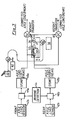
- FIG 3 shows in further detail one method by which the individual axle load values are processed to give a modified load signal according to the weight transfer effect, the corrected axle load then being used by the apportioning multiplier to act on the driver demand (Figure 1) to give an apportioned axle demand.
- Front and rear axle loads are provided by respective sensors 42a, 42b which are designed so as to have a long time constant (e.g. about 4 seconds).
- a braking detector 44 Upon detection by a braking detector 44 that a braking operation has been initiated, the actual axle load sensor signals are disabled by gates 46a, 46b and the prevailing load signals stored in respective stores 48a, 48b.
- the previous mean load measurement occurring over the previous 4 seconds or so is stored as soon as braking is commenced, the actual load signals occurring during braking not being used at all during braking.
- Signals corresponding to the fixed parameters h and L are divided in a divider and the quotient is multiplied in a first multiplier 32 by a signal corresponding to the GVW (the combined axle loads) and then in a second multiplier 34 is multiplied by a signal D corresponding to the deceleration, as provided by a vehicle decelerometer 36.
- the resulting weight transfer quantity W is then added to and subtracted from the signals corresponding to the front and rear axle load signals respectively, to provide corrected axle loads.
- Fig.2 which illustrates the method of compensation by which the braking correction is effected in the open correction loop of Figure 1 by means of an apportioning multiplier 50, to give a corrected pressure demand which is fed to the closed pressure control loop.
- the height of the centre of gravity, h will vary in accordance with the load, in which case the value for h will be computed from a base value representing the unladen value for h plus a component which is proportional to the vehicle total load value.
- This value for h can be assessed for accuracy as follows. If during a braking operation skidding occurs, then both the front and rear axle skid points should occur at the same time for a correctly balanced braking system. However, if skidding occurs only on the front axle, then too much weight transfer allowance has taken place and the value for h can be decremented as an adaptive feature. Conversely, if only rear axle skidding occurs, then insufficient weight transfer allowance has been made and the value of h would be accordingly incremented.
- delays in apportioning can take place because of limitations in the deceleration signal response. This can be countered by producing a transient correction of the deceleration signal D which is derived from the driver braking demand Pi. This is made into a transient signal by the use of a filter 40 (Fig.3) to form a "Fast Driver Demand minus Filtered Driver Demand" signal T, where the filter has a similar time constant to the deceleration measurement. The transient correction T is then added to the measured deceleration from the vehicle decelerometer 36 to produce the effective deceleration D, to give immediate weight transfer figures and rapid apportioning response as the braking becomes effective.
Landscapes
- Engineering & Computer Science (AREA)
- Transportation (AREA)
- Mechanical Engineering (AREA)
- Regulating Braking Force (AREA)
- Hydraulic Control Valves For Brake Systems (AREA)
Description
- The present invention relates to vehicle braking systems of the electronically compensated type wherein, instead of the conventional hydraulic or pneumatic control system operating between the foot pedal and the brake actuators, the analysis of data concerning braking parameters, brake demand, vehicle loading, brake efficiency and the like is performed electronically and the brake actuators are controlled electronically in accordance with such analysis.
- In such systems, the main sources of braking parameter change are measured and the pressure demands to inner closed loop pressure systems are adjusted by outer open loops to compensate for said parameter changes. One of the basic parameters which is measured in such systems is the vehicle loading (axle loads). It is with the method of determining the vehicle loading that the present invention is concerned.
- Our earlier European Patent No. 205 277, a prior art in accordance with Article 54(3) EPC, describes such a braking system wherein driver demand signals to inner closed loop pressure systems for the front and rear brakes are adjusted in accordance with load signals obtained from load sensors associated with front and rear axles of the vehicle, respectively. These load signals are themselves modified to take account of dynamic effects which occur under different operating conditions, such as the weight transfer effect from the rear axle to the front axle which occurs during braking.
- In accordance with the present invention, there is provided a vehicle braking system of the electronically compensated type wherein driver demand signals to inner closed loop pressure systems for the front and rear brakes are adjusted in accordance with load signals obtained from a load sensor associated with an axle of the vehicle, this load signal itself being modified to take account of the weight transfer effect from the rear axle to the front axle which occurs during braking, wherein load sensors are associated with the front and rear axles of the vehicle, respectively, and wherein the magnitude of the weight transfer during a braking operation is calculated electronically from an expression involving the actual deceleration of the vehicle occurring during braking and the gross vehicle weight as determined by stored load signals measured over a period prior to the braking operation taking place no use at all being made in this calculation of load signals occurring during that braking operation, said expression for the calculation of the weight transfer being:
Weight transfer = Decleration x
the deceleration, gross vehicle weight, height of the centre of gravity of the vehicle and the vehicle wheel base being calculated and stored and manipulated electronically to provide dynamic load apportioning between the various inner closed loop pressure systems controlling the front and rear brakes, respectively. - Advantageously, the axle load measurements are made deliberately to have a long time constant so as to be assured of a good average load figure which has been established during the recent normal (non-braking) operation of the vehicle.
- The invention is described further hereinafter, by way of example only, with reference to the accompanying drawings, in which:
- Fig. 1 is a block diagram of a basic electronic control system for operating vehicle brakes;
- Fig. 2 illustrates how braking compensation is achieved; and
- Fig. 3 illustrates one way of achieving dynamic load apportioning in accordance with the present invention.
- The main sources of braking system disturbance in practice are vehicle load and operating gradient, both of which can change suddenly, and brake deterioration which is much more gradual. The sudden changes require compensation by corresponding sudden corrections whilst slow changes can be countered by a gradual adaptation over a time period which can extend into days or weeks depending on vehicle usage.
- In a compensated braking system, a foot pedal transducer generates a first signal indicating the braking level desired by the driver and additional sensors measure the vehicle axle loads and the operating gradient. The system makes appropriate open loop corrections to the brake pressure demands being interpreted from the driver pedal input with the aim of restoring the vehicle deceleration to a level which is in proportion to the driver's demand.
- In Figure 1 there is shown a pressure control loop taking an input Pi from a
brake pedal transducer 10 which is used to provide a pressure error signal Pe by comparison of the input Pi with a pressure transducer output signal Po, this pressure error Pe forming the input to apressure controller 12 which generates an output signal which causes the pressure developed by an electro-pneumatic or electro-hydraulic converter to change in a direction such as to reduce the amplitude of the pressure error Pe. - The nature and circuit of such a
pressure controller 12 depends upon the type of converter employed. Two such converter principles are well known, namely an analogue system in which a valve is employed with pressure output developed porportional to solenoid current and a digital system (as shown) in which a pair ofsimpler solenoid valves relay valve 20 which responds to this control chamber pressure and which re-balances into the closed condition when the brake pressures in the left andright brake actuators - The compensated system of Fig.1 comprises a number of closed loop controllers (only one shown in Fig.1) which are separate for each axle or for each wheel and which are supplied with pressure demands by a
braking correction sub-system 26 such that front and rear systems may receive different pressure demands for equal braking inputs. - One principal disturbance to braking is caused by gradient and this can be sensed by a comparison between deceleration as sensed by a vehicle decelerometer and similar figures generated from speeds sensed by
sensors 23 at the vehicle wheels and differentiated electronically after being combined to form a vehicle reference signal in a manner which is well known in anti-lock systems. The gradient figure generated is a deceleration error DE with a sign which indicates uphill or downhill and which can be added directly to braking demand in thesub-system 26 to achieve appropriate correction of the demand signal Pi. - Another basic parameter which disturbs the braking performance is the vehicle loading and it is known to take axle load readings, generated by suitable transducers on the vehicle, and to use these as correction inputs to the
sub-system 26 for modifying the brake demand signals Pi. This is achieved by the use of a (preferably digital) multiplier which forms a suitably scaled product of pedal input demand and axle load measurement to form the actual pressure demand input Pi which is compared with Po to form the error Pe. - It is with the method determining the vehicle (axle) loading that the present invention is concerned.
- It is well known that during braking a weight transfer effect is experienced between the front and rear axles. Thus, when the vehicle is braking in forward motion, the effective axle load on the front axle increases and that on the rear axle decreases. The load apportioning to the brakes must therefore take into account the weight transfer effect experienced during braking.
- A system in accordance with the preamble of claim 1 is known [EP-A 149 137] in which a single load sensor on one axle provides signals indicative of the vehicle axle load. The instantaneous load prevailing at the instant that a braking operation is initiated is stored. The stored reading is then subsequently compared with dynamic load changes established by the load sensor under actual braking and the difference used to establish the degree of load apportioning between the front and rear axles. In this system, in order to allow for variations resulting from suspension movements, it is necessary for the load readings to be averaged over several time-spaced readings. Thus, a rapidly changing response is not possible. Furthermore, load readings taken during braking are inherently of very doubtful quality since, under all but possibly the lightest braking, the braking forces applied are transmitted through axle and suspension components in which the axle load is being sensed.
- In the present system, in order to overcome this problem, a mean load measurement is stored as soon as braking is commenced as in the known system but load measurements are not used at all during braking. Instead, in the present system, the effect of weight transfer is calculated continuously using parameters measured or stored outside of a braking operation and utilising the following expression, namely

where D = Vehicle deceleration
GVW = Gross vehicle weight
h = Height of the centre of gravity above the ground surface
L = Vehicle wheel base between its front and rear axles. - The Gross Vehicle Weight is taken from the combined axle load measurements which, as explained below, are stored, the deceleration D of the vehicle is measured during the stopping phase and the height h of the centre of gravity and wheel base L are pre-stored quantities.
- The axle load measurements are taken with load transducers (42a, 42b) situated on each axle to be controlled, or by pressure transducers sensing the suspension pressure in air-suspended vehicles, and the signals are fed to the
braking correction sub-system 26 via an open loop. However, the axle load measurements are made deliberately to have a long time constant (for example, approximately 4 seconds), so as to be assured of a good average load figure which has been established during the recent normal (non-braking) operation of the vehicle. The reason for establishing the load value during a non-braking period is due to the disturbance of the load transducers which occurs during a braking period, which is caused by brake reaction stresses in the axles and deflection of the suspension components. Thus it is necessary to utilise stored values which are acquired at a recent earlier time for obtaining the appropriate braking correction. - Figure 3 shows in further detail one method by which the individual axle load values are processed to give a modified load signal according to the weight transfer effect, the corrected axle load then being used by the apportioning multiplier to act on the driver demand (Figure 1) to give an apportioned axle demand. Front and rear axle loads are provided by
respective sensors braking detector 44 that a braking operation has been initiated, the actual axle load sensor signals are disabled bygates respective stores vehicle decelerometer 36. The resulting weight transfer quantity W is then added to and subtracted from the signals corresponding to the front and rear axle load signals respectively, to provide corrected axle loads. It is these latter signals that are then used to modify the braking demand signal Pi, as shown diagrammatically in Fig.2, which illustrates the method of compensation by which the braking correction is effected in the open correction loop of Figure 1 by means of an apportioning multiplier 50, to give a corrected pressure demand which is fed to the closed pressure control loop. - In some circumstances, it may be found that the height of the centre of gravity, h, will vary in accordance with the load, in which case the value for h will be computed from a base value representing the unladen value for h plus a component which is proportional to the vehicle total load value. This value for h can be assessed for accuracy as follows. If during a braking operation skidding occurs, then both the front and rear axle skid points should occur at the same time for a correctly balanced braking system. However, if skidding occurs only on the front axle, then too much weight transfer allowance has taken place and the value for h can be decremented as an adaptive feature. Conversely, if only rear axle skidding occurs, then insufficient weight transfer allowance has been made and the value of h would be accordingly incremented.
- In the system described above where the weight transfer calculation controls the brake apportioning, delays in apportioning can take place because of limitations in the deceleration signal response. This can be countered by producing a transient correction of the deceleration signal D which is derived from the driver braking demand Pi. This is made into a transient signal by the use of a filter 40 (Fig.3) to form a "Fast Driver Demand minus Filtered Driver Demand" signal T, where the filter has a similar time constant to the deceleration measurement. The transient correction T is then added to the measured deceleration from the
vehicle decelerometer 36 to produce the effective deceleration D, to give immediate weight transfer figures and rapid apportioning response as the braking becomes effective.
Claims (4)
- A vehicle braking system of the electronically compensated type wherein driver demand signals to inner closed loop pressure systems for the front and rear brakes are adjusted in accordance with load signals obtained from a load sensor associated with an axle of the vehicle,, this load signal itself being modified to take account of the weight transfer effect from the rear axle to the front axle which occurs during braking, characterised in that load sensors are associated with the front and rear axles of the vehicle, respectively, and that the magnitude of the weight transfer during a braking operation is calculated electronically from an expression involving the actual deceleration of the vehicle occurring during braking and the gross vehicle weight as determined by stored load signals measured over a period prior to the braking operation taking place, no use at all being made in this calculation of load signals occurring during that braking operation,said expression for the calculation of the weight transfer being:

- A vehicle braking system as claimed in claim 1, wherein the axle load measurements are made to have a long time constant so as to obtain an average load figure which has been established during the recent normal, non-braking operation of the vehicle.
- A vehicle braking system as claimed in claim 1 or 2, wherein a transient correction for the deceleration signal, produced by a decelerometer, is derived from the driver's demand signal by subtracting from the driver's demand signal a filtered version of the latter signal obtained using a filter (40) of time constant similar to that of the deceleration measurement.
- A vehicle braking system as claimed in any of claims 1 to 3, wherein stored height values are modified by an additional factor determined from gross vehicle weight or rear axle weight and this value is adapted if skidding does not occur substantially simultaneously at both axles.
Applications Claiming Priority (2)
| Application Number | Priority Date | Filing Date | Title |
|---|---|---|---|
| GB8612066 | 1986-05-17 | ||
| GB868612066A GB8612066D0 (en) | 1986-05-17 | 1986-05-17 | Vehicle braking system |
Publications (4)
| Publication Number | Publication Date |
|---|---|
| EP0246790A2 EP0246790A2 (en) | 1987-11-25 |
| EP0246790A3 EP0246790A3 (en) | 1989-03-15 |
| EP0246790B1 EP0246790B1 (en) | 1990-08-01 |
| EP0246790B2 true EP0246790B2 (en) | 1994-05-18 |
Family
ID=10598043
Family Applications (1)
| Application Number | Title | Priority Date | Filing Date |
|---|---|---|---|
| EP87304148A Expired - Lifetime EP0246790B2 (en) | 1986-05-17 | 1987-05-11 | Vehicle braking system |
Country Status (5)
| Country | Link |
|---|---|
| US (1) | US4795219A (en) |
| EP (1) | EP0246790B2 (en) |
| JP (1) | JP2554653B2 (en) |
| DE (1) | DE3764024D1 (en) |
| GB (1) | GB8612066D0 (en) |
Families Citing this family (37)
| Publication number | Priority date | Publication date | Assignee | Title |
|---|---|---|---|---|
| DE3805589A1 (en) * | 1988-02-23 | 1989-08-31 | Lucas Ind Plc | METHOD AND DEVICE FOR CONTROLLING A BRAKE SYSTEM FOR HEAVY VEHICLES |
| SE462152B (en) * | 1988-09-09 | 1990-05-14 | Saab Scania Ab | SETTING AND ARRANGEMENTS FOR BRAKE ADJUSTMENT BETWEEN A TRUCK VEHICLE AND A CONNECTED SEMITRAILER |
| EP0374484A1 (en) * | 1988-12-22 | 1990-06-27 | Robert Bosch Gmbh | Method and device for tuning of braking action |
| GB8904365D0 (en) * | 1989-02-25 | 1989-04-12 | Lucas Ind Plc | Trailer brake control for towing vehicles having electronic brake control |
| GB8905311D0 (en) * | 1989-03-08 | 1989-04-19 | Lucas Ind Plc | Electronic braking system |
| DE3910209A1 (en) * | 1989-03-30 | 1990-10-04 | Bosch Gmbh Robert | ANTI-BLOCKING CONTROL SYSTEM |
| JPH02267055A (en) * | 1989-04-07 | 1990-10-31 | Isuzu Motors Ltd | Brake control device |
| DE3921309A1 (en) * | 1989-06-29 | 1991-01-10 | Bosch Gmbh Robert | PRESSURE-OPERATED BRAKE SYSTEM FOR MULTI-AXLE MOTOR VEHICLES |
| DE3933652A1 (en) * | 1989-10-09 | 1991-04-11 | Bosch Gmbh Robert | ANTI-BLOCKING CONTROL SYSTEM AND DRIVE-SLIP CONTROL SYSTEM |
| US5240312A (en) * | 1989-10-27 | 1993-08-31 | Mercedes-Benz Ag | Process and system for anti-lock control |
| US5136513A (en) * | 1990-06-11 | 1992-08-04 | Ford Motor Company | Vehicle inertia and center of gravity estimator |
| US5127495A (en) * | 1990-09-28 | 1992-07-07 | Allied-Signal Inc. | Parking brake and method therefor |
| US5148894A (en) * | 1990-10-11 | 1992-09-22 | Allied-Signal Inc. | Disk brake/parking brake with threaded piston rod and motor |
| US5222787A (en) * | 1990-11-20 | 1993-06-29 | Allied-Signal Inc. | Electro-hydraulic braking system |
| US5176431A (en) * | 1991-06-27 | 1993-01-05 | Allied-Signal Inc. | Vehicle deceleration prediction based on vehicle dive |
| US5257856A (en) * | 1991-07-23 | 1993-11-02 | Honda Giken Kogyo Kabushiki Kaisha | Method of and system for controlling brakes |
| GB9118709D0 (en) * | 1991-08-31 | 1991-10-16 | Lucas Ind Plc | Trailer braking control system for a towing vehicle |
| JPH0585327A (en) * | 1991-09-25 | 1993-04-06 | Aisin Seiki Co Ltd | Anti-skid device |
| JP2668751B2 (en) * | 1991-11-30 | 1997-10-27 | 三菱自動車工業株式会社 | Rear wheel braking force control device |
| FR2684946B1 (en) * | 1991-12-13 | 1994-01-28 | Renault Regie Nale Usines | METHOD FOR CONTROLLING THE DECELERATION OF A VEHICLE. |
| JP3532918B2 (en) * | 1991-12-24 | 2004-05-31 | メリター・オートモーティヴ・インコーポレーテッド | Braking force distribution system for multi-axle vehicles considering braking sources other than the basic brake |
| DE4200046C2 (en) * | 1992-01-03 | 1995-08-24 | Daimler Benz Ag | Brake system with adjustable variable front / rear axle brake force distribution |
| JP3382269B2 (en) * | 1992-11-04 | 2003-03-04 | 本田技研工業株式会社 | Vehicle anti-lock control method |
| JPH06166365A (en) * | 1992-12-02 | 1994-06-14 | Sumitomo Electric Ind Ltd | Vehicle body deceleration feedback electronically controlled braking device |
| JP2753793B2 (en) * | 1993-06-03 | 1998-05-20 | 本田技研工業株式会社 | Method for controlling front and rear force of vehicle wheels |
| GB2291945B (en) * | 1994-08-02 | 1999-01-20 | Monroe Auto Equipment Co | Control system for load levelling applications |
| GB9313218D0 (en) * | 1993-06-26 | 1993-08-11 | Lucas Ind Plc | Electronic braking system with system test |
| JP2925461B2 (en) * | 1994-09-27 | 1999-07-28 | 日産ディーゼル工業株式会社 | Rear-end collision prevention device for vehicles |
| US5772289A (en) * | 1994-10-11 | 1998-06-30 | Nissan Diesel Co., Ltd. | Vehicle braking force controller |
| DE4438222B4 (en) * | 1994-10-26 | 2008-02-14 | Knorr-Bremse Systeme für Nutzfahrzeuge GmbH | Method and device for controlling or regulating the brake system of a vehicle |
| DE19501286B4 (en) * | 1995-01-18 | 2010-03-25 | Knorr-Bremse Systeme für Nutzfahrzeuge GmbH | Method and device for controlling a brake system of a vehicle |
| DE19615831A1 (en) * | 1996-04-20 | 1997-10-23 | Bosch Gmbh Robert | Determining characteristic variable of vehicle wheel-brake |
| DE19726116B4 (en) * | 1997-06-20 | 2016-12-08 | Wabco Gmbh | Method for decelerating a vehicle |
| GB2363435B (en) † | 2000-06-17 | 2004-03-03 | Knorr Bremse Systeme | Vehicle braking system using stored vehicle parameters for electronic control of braking |
| US7178881B2 (en) * | 2003-06-25 | 2007-02-20 | Delphi Technologies, Inc. | Rear pressure control and rear dynamic proportioning in a vehicle brake system |
| US9056537B2 (en) * | 2013-03-28 | 2015-06-16 | Bendix Commercial Vehicle Systems Llc | Method to reduce load transfer between axles of a common set during braking |
| US10500916B2 (en) * | 2017-10-23 | 2019-12-10 | Brooks Strong | Axel load monitoring system |
Family Cites Families (10)
| Publication number | Priority date | Publication date | Assignee | Title |
|---|---|---|---|---|
| US3131975A (en) * | 1960-04-21 | 1964-05-05 | North American Aviation Inc | Slope control wheel brake control system |
| US3556608A (en) * | 1968-09-12 | 1971-01-19 | Bendix Corp | Anti-skid means |
| DE1902944C3 (en) * | 1969-01-22 | 1978-10-12 | Dr.Ing.H.C. F. Porsche Ag, 7000 Stuttgart | Control device for avoiding skidding in a curve in motor vehicles |
| IT1143485B (en) * | 1981-04-03 | 1986-10-22 | Ettore Cordiano | BRAKING SYSTEM FOR VEHICLES WITH BRAKE DISTRIBUTOR CONTROLLED BY ELECTRONIC PROCESSOR |
| DE3246201A1 (en) * | 1982-12-14 | 1984-06-14 | Wabco Westinghouse Fahrzeugbremsen GmbH, 3000 Hannover | METHOD AND DEVICE FOR DETERMINING THE WEIGHT OF A VEHICLE |
| JPS59145654A (en) * | 1983-02-09 | 1984-08-21 | Sumitomo Electric Ind Ltd | Brake control for car |
| DE3345694C2 (en) * | 1983-12-17 | 1996-04-04 | Teves Gmbh Alfred | Hydraulic brake system |
| DE3345913A1 (en) * | 1983-12-20 | 1985-06-27 | Robert Bosch Gmbh, 7000 Stuttgart | BRAKE CONTROL SYSTEM |
| GB8513686D0 (en) * | 1985-05-30 | 1985-07-03 | Lucas Ind Plc | Vehicle braking system |
| GB8513688D0 (en) * | 1985-05-30 | 1985-07-03 | Lucas Ind Plc | Vehicle braking system |
-
1986
- 1986-05-17 GB GB868612066A patent/GB8612066D0/en active Pending
-
1987
- 1987-05-11 EP EP87304148A patent/EP0246790B2/en not_active Expired - Lifetime
- 1987-05-11 DE DE8787304148T patent/DE3764024D1/en not_active Expired - Lifetime
- 1987-05-18 JP JP62120985A patent/JP2554653B2/en not_active Expired - Fee Related
- 1987-05-18 US US07/056,626 patent/US4795219A/en not_active Expired - Lifetime
Also Published As
| Publication number | Publication date |
|---|---|
| EP0246790A3 (en) | 1989-03-15 |
| US4795219A (en) | 1989-01-03 |
| GB8612066D0 (en) | 1986-06-25 |
| EP0246790A2 (en) | 1987-11-25 |
| JP2554653B2 (en) | 1996-11-13 |
| EP0246790B1 (en) | 1990-08-01 |
| DE3764024D1 (en) | 1990-09-06 |
| JPS6322761A (en) | 1988-01-30 |
Similar Documents
| Publication | Publication Date | Title |
|---|---|---|
| EP0246790B2 (en) | Vehicle braking system | |
| US4712839A (en) | Vehicle braking system | |
| EP0204483B1 (en) | Vehicle braking system | |
| US5080445A (en) | Trailer brake control for towing vehicles having electronic brake control | |
| EP0385648B1 (en) | Trailer brake control for towing vehicles having electronic brake control | |
| US5136513A (en) | Vehicle inertia and center of gravity estimator | |
| US4512615A (en) | Brake controller | |
| US5646849A (en) | Method for proportionally controlling the brakes of a vehicle based on front and rear wheel speeds | |
| US4677557A (en) | Multiple-axle vehicular braking effort distribution method and system | |
| EP0370678B1 (en) | Trailer braking in electronically controlled braking systems | |
| KR100291128B1 (en) | Brake system | |
| US5482359A (en) | System and method for determining relative vehicle mass | |
| US5344222A (en) | Method for controlling a braking operation including determining brake coefficient forces | |
| US4647115A (en) | Vehicular anti-brake lock system and method of controlling braking pressure | |
| GB2136519A (en) | Method of and device for controlling the distribution of brake force | |
| US7066559B2 (en) | Brake pressure estimating apparatus and method | |
| EP0386952B1 (en) | Electronic braking system | |
| US5887957A (en) | Circuit arrangement for a brake system with electronic brake force distribution control | |
| US5938295A (en) | Process and apparatus for controlling the brake system of a vehicle | |
| US5855419A (en) | Process for controlling a distribution of braking force in a vehicle | |
| US6282479B1 (en) | Vehicle stability enhancement system in high center of gravity vehicle | |
| EP0301243B1 (en) | Trailer mounted tractor-trailer brake control system | |
| EP0820393B1 (en) | Differential braking control in road vehicles | |
| US5941924A (en) | Method and device for controlling a vehicle braking system | |
| US6272419B1 (en) | Method for controlling vehicle behavior during cornering and a braking system for implementation thereof |
Legal Events
| Date | Code | Title | Description |
|---|---|---|---|
| PUAI | Public reference made under article 153(3) epc to a published international application that has entered the european phase |
Free format text: ORIGINAL CODE: 0009012 |
|
| AK | Designated contracting states |
Kind code of ref document: A2 Designated state(s): DE FR GB IT |
|
| PUAL | Search report despatched |
Free format text: ORIGINAL CODE: 0009013 |
|
| AK | Designated contracting states |
Kind code of ref document: A3 Designated state(s): DE FR GB IT |
|
| 17P | Request for examination filed |
Effective date: 19890210 |
|
| 17Q | First examination report despatched |
Effective date: 19890622 |
|
| GRAA | (expected) grant |
Free format text: ORIGINAL CODE: 0009210 |
|
| AK | Designated contracting states |
Kind code of ref document: B1 Designated state(s): DE FR GB IT |
|
| ITF | It: translation for a ep patent filed | ||
| REF | Corresponds to: |
Ref document number: 3764024 Country of ref document: DE Date of ref document: 19900906 |
|
| ET | Fr: translation filed | ||
| PLBI | Opposition filed |
Free format text: ORIGINAL CODE: 0009260 |
|
| ITTA | It: last paid annual fee | ||
| 26 | Opposition filed |
Opponent name: ROBERT BOSCH GMBH Effective date: 19910423 |
|
| PUAH | Patent maintained in amended form |
Free format text: ORIGINAL CODE: 0009272 |
|
| STAA | Information on the status of an ep patent application or granted ep patent |
Free format text: STATUS: PATENT MAINTAINED AS AMENDED |
|
| 27A | Patent maintained in amended form |
Effective date: 19940518 |
|
| AK | Designated contracting states |
Kind code of ref document: B2 Designated state(s): DE FR GB IT |
|
| ITF | It: translation for a ep patent filed | ||
| ET3 | Fr: translation filed ** decision concerning opposition | ||
| REG | Reference to a national code |
Ref country code: FR Ref legal event code: TP |
|
| REG | Reference to a national code |
Ref country code: GB Ref legal event code: IF02 |
|
| REG | Reference to a national code |
Ref country code: GB Ref legal event code: 732E |
|
| REG | Reference to a national code |
Ref country code: GB Ref legal event code: 732E |
|
| APAH | Appeal reference modified |
Free format text: ORIGINAL CODE: EPIDOSCREFNO |
|
| PGFP | Annual fee paid to national office [announced via postgrant information from national office to epo] |
Ref country code: DE Payment date: 20060508 Year of fee payment: 20 |
|
| PGFP | Annual fee paid to national office [announced via postgrant information from national office to epo] |
Ref country code: GB Payment date: 20060510 Year of fee payment: 20 |
|
| PGFP | Annual fee paid to national office [announced via postgrant information from national office to epo] |
Ref country code: FR Payment date: 20060515 Year of fee payment: 20 |
|
| PGFP | Annual fee paid to national office [announced via postgrant information from national office to epo] |
Ref country code: IT Payment date: 20060531 Year of fee payment: 20 |
|
| REG | Reference to a national code |
Ref country code: GB Ref legal event code: PE20 |
|
| PG25 | Lapsed in a contracting state [announced via postgrant information from national office to epo] |
Ref country code: GB Free format text: LAPSE BECAUSE OF EXPIRATION OF PROTECTION Effective date: 20070510 |