EP0246711A2 - Vorrichtung zum Erkennen der Form und Dimension von Flaschen oder dergleichen - Google Patents
Vorrichtung zum Erkennen der Form und Dimension von Flaschen oder dergleichen Download PDFInfo
- Publication number
- EP0246711A2 EP0246711A2 EP87200960A EP87200960A EP0246711A2 EP 0246711 A2 EP0246711 A2 EP 0246711A2 EP 87200960 A EP87200960 A EP 87200960A EP 87200960 A EP87200960 A EP 87200960A EP 0246711 A2 EP0246711 A2 EP 0246711A2
- Authority
- EP
- European Patent Office
- Prior art keywords
- examined
- transmitter
- receiver
- receivers
- bottles
- Prior art date
- Legal status (The legal status is an assumption and is not a legal conclusion. Google has not performed a legal analysis and makes no representation as to the accuracy of the status listed.)
- Withdrawn
Links
- 238000005259 measurement Methods 0.000 claims abstract description 10
- 238000000034 method Methods 0.000 claims description 3
- 230000008569 process Effects 0.000 claims description 3
- 238000003384 imaging method Methods 0.000 claims 1
- 230000007704 transition Effects 0.000 description 5
- 230000008878 coupling Effects 0.000 description 2
- 238000010168 coupling process Methods 0.000 description 2
- 238000005859 coupling reaction Methods 0.000 description 2
- 230000001934 delay Effects 0.000 description 2
- 230000000694 effects Effects 0.000 description 2
- 230000002093 peripheral effect Effects 0.000 description 2
- 239000004033 plastic Substances 0.000 description 2
- 229920003023 plastic Polymers 0.000 description 2
- 230000005855 radiation Effects 0.000 description 2
- 238000000429 assembly Methods 0.000 description 1
- 230000008901 benefit Effects 0.000 description 1
- 230000008859 change Effects 0.000 description 1
- 230000002349 favourable effect Effects 0.000 description 1
- 230000005484 gravity Effects 0.000 description 1
- 239000007788 liquid Substances 0.000 description 1
- 239000000463 material Substances 0.000 description 1
- 239000013307 optical fiber Substances 0.000 description 1
- 238000005192 partition Methods 0.000 description 1
- 230000000717 retained effect Effects 0.000 description 1
- 230000000630 rising effect Effects 0.000 description 1
- 238000005096 rolling process Methods 0.000 description 1
Images


Classifications
-
- G—PHYSICS
- G10—MUSICAL INSTRUMENTS; ACOUSTICS
- G10K—SOUND-PRODUCING DEVICES; METHODS OR DEVICES FOR PROTECTING AGAINST, OR FOR DAMPING, NOISE OR OTHER ACOUSTIC WAVES IN GENERAL; ACOUSTICS NOT OTHERWISE PROVIDED FOR
- G10K11/00—Methods or devices for transmitting, conducting or directing sound in general; Methods or devices for protecting against, or for damping, noise or other acoustic waves in general
- G10K11/18—Methods or devices for transmitting, conducting or directing sound
- G10K11/26—Sound-focusing or directing, e.g. scanning
- G10K11/28—Sound-focusing or directing, e.g. scanning using reflection, e.g. parabolic reflectors
-
- B—PERFORMING OPERATIONS; TRANSPORTING
- B07—SEPARATING SOLIDS FROM SOLIDS; SORTING
- B07C—POSTAL SORTING; SORTING INDIVIDUAL ARTICLES, OR BULK MATERIAL FIT TO BE SORTED PIECE-MEAL, e.g. BY PICKING
- B07C5/00—Sorting according to a characteristic or feature of the articles or material being sorted, e.g. by control effected by devices which detect or measure such characteristic or feature; Sorting by manually actuated devices, e.g. switches
- B07C5/04—Sorting according to size
- B07C5/12—Sorting according to size characterised by the application to particular articles, not otherwise provided for
- B07C5/122—Sorting according to size characterised by the application to particular articles, not otherwise provided for for bottles, ampoules, jars and other glassware
-
- G—PHYSICS
- G01—MEASURING; TESTING
- G01S—RADIO DIRECTION-FINDING; RADIO NAVIGATION; DETERMINING DISTANCE OR VELOCITY BY USE OF RADIO WAVES; LOCATING OR PRESENCE-DETECTING BY USE OF THE REFLECTION OR RERADIATION OF RADIO WAVES; ANALOGOUS ARRANGEMENTS USING OTHER WAVES
- G01S15/00—Systems using the reflection or reradiation of acoustic waves, e.g. sonar systems
- G01S15/88—Sonar systems specially adapted for specific applications
- G01S15/89—Sonar systems specially adapted for specific applications for mapping or imaging
- G01S15/8906—Short-range imaging systems; Acoustic microscope systems using pulse-echo techniques
- G01S15/8934—Short-range imaging systems; Acoustic microscope systems using pulse-echo techniques using a dynamic transducer configuration
- G01S15/8938—Short-range imaging systems; Acoustic microscope systems using pulse-echo techniques using a dynamic transducer configuration using transducers mounted for mechanical movement in two dimensions
-
- G—PHYSICS
- G07—CHECKING-DEVICES
- G07F—COIN-FREED OR LIKE APPARATUS
- G07F7/00—Mechanisms actuated by objects other than coins to free or to actuate vending, hiring, coin or paper currency dispensing or refunding apparatus
- G07F7/06—Mechanisms actuated by objects other than coins to free or to actuate vending, hiring, coin or paper currency dispensing or refunding apparatus by returnable containers, i.e. reverse vending systems in which a user is rewarded for returning a container that serves as a token of value, e.g. bottles
- G07F7/0609—Mechanisms actuated by objects other than coins to free or to actuate vending, hiring, coin or paper currency dispensing or refunding apparatus by returnable containers, i.e. reverse vending systems in which a user is rewarded for returning a container that serves as a token of value, e.g. bottles by fluid containers, e.g. bottles, cups, gas containers
Definitions
- a narrow light beam is repeatedly swept in the axial direction of the bottle during conveying the bottle, e.g. by means of a rotating disk, which beam, if not interrupted by the bottle, will hit a row of light-sensitive cells directed parallel to the axial direction of the bottle, and this, if required, by means of an optical fibre assembly, which is repeated for a number of intersection planes of the bottle during the passage of said bottle.
- the output signals series of these cells represent, then, the peripheral shape of the bottle, which signal series are subsequently compared with reference series valid for acceptable bottles. In the case of correspondence, the bottle is carried off and a credit coupon is produced.
- Such devices have some disadvantages. Such devices are to be included in a wall between the shop and the storage space, so that these devices are generally installed in a part of the shop in which also the goods are present, so that it is possible to take away filled bottles from the shop and to place them into the device with the aim of cashing the deposit money. Moreover the purchase price of such devices is high, and said devices are sensitive to failures. Placing the bottles on a rotating disc is for many people objectionable, and toppling bottles are refused which delays the operation. Moreover the accepted bottles are generally shifted from the disc on a table which, if no additional expensive discharge means are provided, is to be emptied in time so as to avoid congestion.
- the device of the invention is characterised by one or more transmitters for emitting a beam of ultrasonic pulses towards a point near the axial plane of an object to be examined, by one or more corresponding receivers for the pulses reflected by said object, by means for moving said transmitters and receivers or the object, as the case may be, parallel to the axis of said object, and by processing means adapted to determine the transit time differences between the emitted and corresponding received pulses, and to derive therefrom the distance of said object in respect of the transmitter, and for comparing said differences with reference values and deriving therefrom the shape and dimensions of the examined object.
- a transmitter and a corresponding receiver are formed by the same electro-acoustic transducer.
- the device of the invention operates with depth or distance measurement by means of ultrasonics in one single passage.
- Ultrasonic transmitters and receivers are more robust and less sensitive to failures than the laser sources used in the known devices, and by the depth measurement in one passage a sufficiently sharp shape determination can be obtained, so that the operation is faster.
- ultrasonic devices are less expensive than the known ones.
- the receiver can be formed by the same element as the transmitter.
- an ultrasonic transmitter 1 is diagrammatically shown, which, in particular, can also operate as a receiver, said transmitter being adapted for emitting successive ultrasonic pulses as a conical beam 2.
- Said transmitter is movable along a horizontal path 3, three positions A, B and C thereof being shown.
- a surface 4 including two parts 4A and 4B parallel to the path 3 and having different distances in respect of the path 3, as well as an oblique portion 4C are shown.
- the beams 2A and 2B are reflected as diverging beams 5A and 58 resp. against these surface portions 4A and 4B resp., and a portion thereof is incident again on the transmitter/receiver l,and this at an instant that depends on the transit time of the sound over two times the distance between the transmitter/receiver and the surface portion in question.
- the time interval between a received pulse and the corresponding emitted pulse is a measure for the distance of the surface portion in question to the transmitter/receiver. This time interval can be measured with known electronic apparatuses, and can, in particular, be compared with reference values for known distances.
- the energy taken up by the receiver is smaller than the emitted energy.
- the output pulses of the receiver corresponding to the reflected pulses are, therefore weaker than the output pulses corresponding to the transmitter pulses, and are, therefore, clearly distinct therefrom.
- the processing circuit of the device should, of course, be adapted to process these weaker signals.
- the beam 5c If the surface 4, as shown at 4c, has an inclination, the beam 5c, if the inclination angle thereof exceeds a given value, will, on reception by the receiver lc,be weakened in energy so that a considerably weakened signal or no signal at all is received.
- Fig. 2 diagrammatically shows how, in this manner, the shape and dimensions of a bottle 6 having a neck 7 and a transition portion 8 between said neck 7 and the body of the bottle can be determined.
- Said bottle 6 is supported parallel to the path 3 of the transmitter/receiver 1, and in particular horizontally, on a support 9.
- the path 3 extends between two terminal points 10 and 11, which are so far apart that the largest prevailing bottles still can be covered.
- the pulse series produced by the receiver and consisting of a plurality of pairs of output pulses corresponding to the transmitted acoustical pulse and the received reflected acoustical pulses respectively, is sent to a processing circuit 12 known per se, in which said output pulses are processed to produce corresponding transit time differences corresponding to the distances in question, which are, then, compared in a comparator 13 with corresponding reference series which have been determined for acceptable bottle shapes and dimensions. In the case of correspondence the bottle is accepted.
- processing circuits are known per se, and have, therefore, not to be described in detail.
- the transition portion 8 only a measurement takes place in those parts having an inclination lying below the threshold value mentioned above.
- the length of the bottles is derived from the beginning and the end of the measurement series proper where the beam is reflected against the support 9.
- Fig. 3 shows a bottle 6 having, moreover, a constriction which, if the inclination of the transition portions 14 and 15 is large, cannot be accurately followed.
- two or more transmitters/receivers 1, 1', 1" can be used which are directed at different angles in respect of the axis of the bottle, the transmitters/receivers 1' and 1" having opposite inclinations. These angles are chosen in such a manner that the beam reflected against the parallel wall portions sufficiently reaches the receiver, and always one of the receivers will receive from an inclined surface a sufficient signal. For instance the receiver 1' will receive the beam reflected against the surface portion 14, and the receiver 1" the beam reflected against the portion 15.
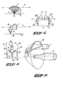
- a transducer having a surface which is curved in such a manner that the transmitted acoustic beam is incident on the reflecting object convergent- ly from different angles of incidence with an aperture angle a.
- concave and in particular parabolic mirrors 16 by means of which a convergent beam is obtained which is incident under different angles as shown in Figs. 4B and 4C.
- the mirror 16 produces a beam with an aperture angle ⁇
- two mirrors 16' and 16" being associated with a transducer 1' and 1" respectively, produce a beam with an aperture angle ⁇ /2.
- the latter case corresponds to the case of Fig. 3, but now the task of the transducer 1 has been spread over both transducers 1' and 1".
- the latter should, of course move with the associated transducers 1 if the latter are moved along an object to be examined. It is, then, not necessary that the different beams will be directed to the same point of the bottle surface, provided that the deviation from the axial plane is not too large.
- Fig. 5 shows how a parabolic mirror according to Fig. 4B or C can be a part of a paraboloidical ring having an axis which substantial coincides with the axis of a bottle to be examined.
- Such mirrors can, for instance, be cut from a ring of plastics or an other suitable material formed on a template, or can be made directly by means of moulds produced by using such a template.
- Fig. 6 shows a diagrammatic representation in section of a device according to the invention.
- the support 9 having the shape of plates 17 arranged in the manner of a V will accurately centre a bottle irrespective its diameter, which also holds for square bottles. Inserting a bottle into such a support is easy, and all difficulties rising from an inaccurate positioning are avoided.
- the plates 17 are, in particular, mounted on hinges 18, and are being maintained in the position shewn by means of locking elements not shown, said locking elerents being released on the reception of an acceptance signal of the final stage 13, and then the bottle 6 can drop into a collecting bin 19.
- Said collecting bin can, in particular, be provided with a central partition 20 if the acceptance signals make a distinction between larger and smaller bottles, and, with the locking elements, the plates 17 can be operated separately, so that larger bottles will drop in one and smaller ones in the other bin half. After a bottle has dropped out the plates can be rotated back by means of a motor or the like.
- the bin 19 is, in particular, freely arranged in a housing as indicated diagrammatically, said housing being adapted to be placed in an arbitrary point, and in particular outside the restricted sales area. Means can be provided for indicating that the bin 19 is getting full, so as to allow to produce a warning signal in time. It is, of course, also possible to discharge the bottles continuously by means of a conveyor, chute or the like. Moreover, in the casing 21 a door 22 is provided for closing the intake space for the bottles, which door can be provided in the known manner with electric contacts preventing the operation of the device as long as the door is open, said door being locked as long as the device is operative.
- Fig. 7 shows a diagrammatic representation of a practical embodiment of a device according to the invention.
- This device comprises a casing 21 with, at its front side, an opening 22.
- a substantially cylindric at body 23 is arranged which is rotatable around an axis 24, which not necessarily coincides with the cylinder axis.
- a plurality of walls are provided extending over the width of the opening 22, viz. a closing wall 25, and two contiguous walls 9' and 17' arranged at an angle, the latter forming the bottle support during the examination thereof by means of the assembly 1/16.
- Said walls 9' and 17' essentially correspond to the parts 9 and 17 of Fig. 6.
- the wall 17' is connected by means of a hinge 18' with the wall 9', and is, in the condition of rest according to Fig. 7A, retained by means of a latch 25.
- a shielding wall 26 shields in the condition of rest shown in Fig. 7A the assembly 1,16.
- the latter wall can be a part of the cylindric body 23, but can also be a separately movable wall which is coupled to said cylinder 23 in some suitable manner.
- the user rotates the cylinder 23 towards the position shown in Fig. 78, in which position the cylinder is locked by means of a latch 27.
- the bottle 6 is then supported by the walls 9' and 17'.
- Means 28 which are diagrammatically shown can be provided for determining the weight of the bottle is this is desired. At a deviating weight the bottle can be refused.
- the latch 25 is released allowing the wall 17' to turn down as shown in Fig. 7B by interrupted lines, after which the latch 27 is released, so that the cylinder 23 will return again to the initial position.
- Coupling or guiding means not shown are provided for turning the wall 17' back again during this reverse rotation, and to engage said wall with the latch 25. If the examination leads to a refusal of the bottle, the latch 25 is not released which is only the case for the latch 27, so that, then, the body 23 with the bottle will return to the initial position, after which the bottle can be taken away again.
- the casing 21 comprises a door 29 through which a separate bin 19 on wheels 30 can be rolled inwards.
- This bin consists, for instance, of a rigid frame made of channel rods between which wire grid is provided.
- This bin has a movable bottom 31, which can be shifted within said bin, and the back wall thereof is provided with slots 32 through which lifting arms 33 can be inserted which are to be engaged with the lower side of the bottom 31. Said arms 33 can be. moved up and down by means of associated screw spindles 34 coupled with a motor 35.
- the arms 33 When introducing an empty bin 19, the arms 33 are in their lowest position so that they can be placed below the bottom. Thereafter the motor 35 is switched on in order to move said bottom towards its highest position. Bottles rolling from the cylinder 23 when turning the wall 17' will fall, then, into the bin over the smallest possible height. As the bin is being filled, the arms 33 are moved downwards so as to maintain a substantially constant fall height for the bottles so as to reduce the danger of being damaged.
- Fig. 7A shows a special auxiliary means for uniformly distributing the bottles in the bin and for controlling the lifting arms 33.
- a disc 36 is provided at the upper side of the bin which is connected to a vertical driving shaft 37 at a small inclination with the horizontal plane.
- This shaft is coupled, by means of a slipping clutch 38, with a driving motor 39.
- the bottles will, now, fall first on the disc 36, and roll, because of the slight inclination thereof, from the disc into the bin 19, but, since this disc and also the line of largest inclination thereof is rotating, the bottles will be uniformly distributed over the bin 19.
- the clutch 38 begins to slip. This is detected by a sensor 40 which, then, switches on the motor 35 so as to lower the arms 33 over a given distance, after which the bottles can be distributed again by the disc 30. This continues until the bin 19 is completely filled. Then a warning signal is produced, and the operation of the device is interrupted until a new bin has been inserted.
- This device comprises, of course, the current means for supplying credit coupons, and, moreover, preferably comprises means for printing a list of bottles introduced into the bin, which print can be attached, either or not automatically, to a filled bin 19.
- cover wall 26 is not mounted on the cylinder itself, it can be mounted on separate swing arms which are coupled to the cylinder 23 by means of a pin/slot coupling, and this in such a manner that, when rotating said cylinder inwards, said wall is swung away.
- the axis of the cylinder 23 can be situated so much lower than its axis of rotation 24 that this cylinder will automatically return to the position of Fig. 7A under the influence of gravity, but it is also possible to use springs to that end. It is also possible to use the position of Fig. 7B as the position of rest, so that, then, the cylinder 23 should be rotated for inserting or removing a bottle.
- the means 28 for weight determination can be left out if an additional protection against inserting full bottles is not required. However such means can be required if accepting too light plastics bottles having the shape of an acceptable bottle,and/or retracting a bottle after measurement by means of a string or the like, should be avoided.
- a specific advantage of the device described above is that,in one single passage of a transmitter/receiver,an accurate determination of the shape and dimensions of a bottle or similar liquid container can be obtained, so that the operation is very fast.
- the transmitter/receiver will be moved alternately in the one nr the other sense so as to avoid delays. Said movement can take place contiuously or stepwise by means of a driving belt or screw or the like.
Landscapes
- Physics & Mathematics (AREA)
- Engineering & Computer Science (AREA)
- Acoustics & Sound (AREA)
- Radar, Positioning & Navigation (AREA)
- Remote Sensing (AREA)
- General Physics & Mathematics (AREA)
- Multimedia (AREA)
- Computer Networks & Wireless Communication (AREA)
- Sorting Of Articles (AREA)
- Length Measuring Devices Characterised By Use Of Acoustic Means (AREA)
Applications Claiming Priority (2)
| Application Number | Priority Date | Filing Date | Title |
|---|---|---|---|
| NL8601309A NL8601309A (nl) | 1986-05-22 | 1986-05-22 | Inrichting voor het herkennen van de vorm en afmetingen van flessen of dergelijke. |
| NL8601309 | 1986-05-22 |
Publications (2)
| Publication Number | Publication Date |
|---|---|
| EP0246711A2 true EP0246711A2 (de) | 1987-11-25 |
| EP0246711A3 EP0246711A3 (en) | 1989-08-23 |
Family
ID=19848052
Family Applications (1)
| Application Number | Title | Priority Date | Filing Date |
|---|---|---|---|
| EP87200960A Withdrawn EP0246711A3 (en) | 1986-05-22 | 1987-05-21 | A device for recognising the shape and dimension of bottles or the like |
Country Status (2)
| Country | Link |
|---|---|
| EP (1) | EP0246711A3 (de) |
| NL (1) | NL8601309A (de) |
Cited By (5)
| Publication number | Priority date | Publication date | Assignee | Title |
|---|---|---|---|---|
| WO1991005220A1 (en) * | 1989-09-28 | 1991-04-18 | Environmental Products Corporation | Acoustic holographic array measurement device and related method |
| WO1998002853A1 (en) * | 1996-07-12 | 1998-01-22 | Tomra Systems Asa | Device for handling containers |
| EP1811468A1 (de) * | 2006-01-24 | 2007-07-25 | Wincor Nixdorf International GmbH | Verteilvorrichtung für einen Rücknahmeautomat |
| ITBO20120686A1 (it) * | 2012-12-19 | 2014-06-20 | Marchesini Group Spa | Sistema di carico e di alimentazione di articoli per una apparecchiatura di confezionamento operante in ambiente sterile |
| US20180295879A1 (en) * | 2017-04-18 | 2018-10-18 | Gyro, LLC | Reward-dispensing, cigarette-waste receptacle |
Family Cites Families (7)
| Publication number | Priority date | Publication date | Assignee | Title |
|---|---|---|---|---|
| DE1928367B2 (de) * | 1969-06-04 | 1975-04-30 | Siemens Ag, 1000 Berlin Und 8000 Muenchen | Nach dem Impuls-Echoverfahren arbeitendes Ultraschall-Bildgerät |
| NO135609C (de) * | 1975-06-03 | 1977-05-11 | Tore Planke | |
| US4207973A (en) * | 1977-04-13 | 1980-06-17 | Henry Stampleman | Article actuated coin dispensing closure for article collecting receptacles |
| US4332016A (en) * | 1979-01-26 | 1982-05-25 | A/S Tomra Systems | Method, apparatus and transducer for measurement of dimensions |
| GB2102174A (en) * | 1981-07-18 | 1983-01-26 | Carol Anne Rees | Waste item recovery devices |
| US4454028A (en) * | 1982-07-30 | 1984-06-12 | Point Of Purchase Recycling, Inc. | Can sorting method and apparatus |
| GB8404689D0 (en) * | 1984-02-22 | 1984-03-28 | Moore J L | Vending machine |
-
1986
- 1986-05-22 NL NL8601309A patent/NL8601309A/nl not_active Application Discontinuation
-
1987
- 1987-05-21 EP EP87200960A patent/EP0246711A3/en not_active Withdrawn
Cited By (8)
| Publication number | Priority date | Publication date | Assignee | Title |
|---|---|---|---|---|
| WO1991005220A1 (en) * | 1989-09-28 | 1991-04-18 | Environmental Products Corporation | Acoustic holographic array measurement device and related method |
| WO1998002853A1 (en) * | 1996-07-12 | 1998-01-22 | Tomra Systems Asa | Device for handling containers |
| EP1811468A1 (de) * | 2006-01-24 | 2007-07-25 | Wincor Nixdorf International GmbH | Verteilvorrichtung für einen Rücknahmeautomat |
| NO338872B1 (no) * | 2006-01-24 | 2016-10-31 | Wincor Nixdorf Int Gmbh | Returautomat |
| ITBO20120686A1 (it) * | 2012-12-19 | 2014-06-20 | Marchesini Group Spa | Sistema di carico e di alimentazione di articoli per una apparecchiatura di confezionamento operante in ambiente sterile |
| EP2746202A1 (de) * | 2012-12-19 | 2014-06-25 | Marchesini Group S.p.A. | Verpackungsvorrichtung in einer sterilen Umgebung mit einem Beladungs- und Versorgungssystem für Artikel |
| US9637261B2 (en) | 2012-12-19 | 2017-05-02 | Marchesini Group S.P.A. | Packing apparatus in a sterile environment with a loading and supply system of articles |
| US20180295879A1 (en) * | 2017-04-18 | 2018-10-18 | Gyro, LLC | Reward-dispensing, cigarette-waste receptacle |
Also Published As
| Publication number | Publication date |
|---|---|
| NL8601309A (nl) | 1987-12-16 |
| EP0246711A3 (en) | 1989-08-23 |
Similar Documents
| Publication | Publication Date | Title |
|---|---|---|
| US4532859A (en) | Method for identification of metal boxes or cans and an apparatus for carrying out said method | |
| US4749273A (en) | Method and apparatus for determining the material flow rate of conveying mechanisms | |
| EP0324285B1 (de) | Verfahren und Vorrichtung zum Prüfen eines transparenten Behälters | |
| US4459487A (en) | Method and apparatus for identifying objects such as bottles by shape | |
| JP2804469B2 (ja) | カプセル検出装置 | |
| US5589636A (en) | Method of and apparatus for the detection of an ultrasonic field | |
| WO1997035279A1 (en) | Gaming token tray employing ultrasonic token counting | |
| CA1239454A (en) | Pit detecting | |
| EP0238589A1 (de) | Ortungsverfahren und -vorrichtung die eine abschätzung des zertrümmerungsgrades der konkremente während einer lithotripsie ermöglichen. | |
| US4633236A (en) | Mailbox | |
| GB2190749A (en) | Monitoring the level of a stack of coins by a pulse-echo method | |
| EP0246711A2 (de) | Vorrichtung zum Erkennen der Form und Dimension von Flaschen oder dergleichen | |
| EP0310470A1 (de) | Verfahren und Vorrichtung zum Lokalisieren und Zertrümmern einer anatomischen Anomalie durch elastische Wellen mit Zielnachführung und automatischer Wellenauslösung | |
| JPH0657325B2 (ja) | ロータ認識装置 | |
| US3415370A (en) | Empty bottle bottom and neck inspection machine using radiation sensitive means | |
| EP0773427A4 (de) | Referenzlageregelungsvorrichtung für einen laser | |
| US5076502A (en) | System for discriminating radiation-contaminated fragments and apparatus for measuring radioactivity of fragments | |
| JP2003518674A (ja) | 自動販売機とコイン処理装置 | |
| EP0343411B1 (de) | Vorrichtung zur Untersuchung von Oberflächenfehlstellen in Kernbrennstofftabletten | |
| EP1955012B1 (de) | Verfahren und vorrichtung zum überprüfen der seitenwandkontur eines behälters | |
| US4537075A (en) | Position control | |
| EP0706062B1 (de) | Gerät zur Erkennung von dreidimensionalen Formen | |
| EP0057648A1 (de) | Verfahren und Vorrichtung zur Überwachung von Regelstäben eines Kernreaktors | |
| US4731802A (en) | Apparatus for counting substantially cylindrical articles | |
| JPH11123142A (ja) | 液体容器の吐出安全装置 |
Legal Events
| Date | Code | Title | Description |
|---|---|---|---|
| PUAI | Public reference made under article 153(3) epc to a published international application that has entered the european phase |
Free format text: ORIGINAL CODE: 0009012 |
|
| AK | Designated contracting states |
Kind code of ref document: A2 Designated state(s): AT BE CH DE ES FR GB GR IT LI LU NL |
|
| 17P | Request for examination filed |
Effective date: 19880520 |
|
| PUAL | Search report despatched |
Free format text: ORIGINAL CODE: 0009013 |
|
| AK | Designated contracting states |
Kind code of ref document: A3 Designated state(s): AT BE CH DE ES FR GB GR IT LI LU NL |
|
| 17Q | First examination report despatched |
Effective date: 19920122 |
|
| STAA | Information on the status of an ep patent application or granted ep patent |
Free format text: STATUS: THE APPLICATION IS DEEMED TO BE WITHDRAWN |
|
| 18D | Application deemed to be withdrawn |
Effective date: 19911203 |
|
| RIN1 | Information on inventor provided before grant (corrected) |
Inventor name: LAUW, TJING HAN |