EP0246637A2 - Verfahren zur Überwachung von Schwingungen in rotierenden Geräten - Google Patents
Verfahren zur Überwachung von Schwingungen in rotierenden Geräten Download PDFInfo
- Publication number
- EP0246637A2 EP0246637A2 EP87107353A EP87107353A EP0246637A2 EP 0246637 A2 EP0246637 A2 EP 0246637A2 EP 87107353 A EP87107353 A EP 87107353A EP 87107353 A EP87107353 A EP 87107353A EP 0246637 A2 EP0246637 A2 EP 0246637A2
- Authority
- EP
- European Patent Office
- Prior art keywords
- data
- signal
- rotating
- frequency domain
- rotating part
- Prior art date
- Legal status (The legal status is an assumption and is not a legal conclusion. Google has not performed a legal analysis and makes no representation as to the accuracy of the status listed.)
- Ceased
Links
Images


Classifications
-
- G—PHYSICS
- G01—MEASURING; TESTING
- G01H—MEASUREMENT OF MECHANICAL VIBRATIONS OR ULTRASONIC, SONIC OR INFRASONIC WAVES
- G01H3/00—Measuring characteristics of vibrations by using a detector in a fluid
-
- G—PHYSICS
- G01—MEASURING; TESTING
- G01H—MEASUREMENT OF MECHANICAL VIBRATIONS OR ULTRASONIC, SONIC OR INFRASONIC WAVES
- G01H1/00—Measuring characteristics of vibrations in solids by using direct conduction to the detector
- G01H1/003—Measuring characteristics of vibrations in solids by using direct conduction to the detector of rotating machines
-
- G—PHYSICS
- G01—MEASURING; TESTING
- G01H—MEASUREMENT OF MECHANICAL VIBRATIONS OR ULTRASONIC, SONIC OR INFRASONIC WAVES
- G01H11/00—Measuring mechanical vibrations or ultrasonic, sonic or infrasonic waves by detecting changes in electric or magnetic properties
- G01H11/06—Measuring mechanical vibrations or ultrasonic, sonic or infrasonic waves by detecting changes in electric or magnetic properties by electric means
Definitions
- This invention relates generally to the monitoring of rotating machinery and more particularly to the analyzing of rotating machinery vibration data.
- Rotating machinery such as a shaft in an axial or centrifrugal compressor, turbine or motor
- Rotating machinery is generally monitored, either continuously or intermittently to ensure safe operation of the machine and to determine if and when maintenance is necessary.
- One common method of monitoring such machinery is to monitor the vibrations of the rotating part as the part rotates through its periodic movement. The distribution of frequenices present in the vibration signal and the magnitude of such vibrations give an indication that machine operating problems may arise.
- One commonly used technique for monitoring rotating part vibration is the vector nulling method.
- This technique employs a tracking filter to determine the amplitude and phase of the rotating components during normal running speed and during a slower speed wherein only runout vibration is present. The runout vector is then subtracted from the operating vector to provide operating vibration data.
- This technique is relatively easy to use but is disadvantageous because it compensates runout only at the rotating speed.
- Another method for monitoring rotating part vibration is the time domain compensation technique which comprises acquiring and digitizing a data sample of runout and then subtracting this sample from data samples obtained during operation of the machinery. This technique is effective but is complicated and difficult to implement and carry out.
- a method for monitoring the vibrations of a rotating part comprising:
- rotating means the periodic movement of a part. Movement of the part from a starting point and back to the starting point constitutes one rotation or revolution. Generally, but not necessarily, the part will rotate in a circular manner.
- rpm means rotation or revolutions of the part over a defined time period. One example of this would be revolutions per minute.
- the rotating part is a shaft which rotates in a circular motion.
- Figure 1 is a schematic representation of one preferred hardware arrangement for carrying out the method of this invention.
- rotating shaft 101 is shown in radial cross-section.
- the shaft may be rotating at any rotational speed and either in the clockwise or counterclockwise direction.
- the vibrations of the rotating shaft 101 are monitored by proximity probe 102.
- the data signal from the proximity probe is passed into proximeter 103 which supplies voltage to proximity probe 102 and conditions the probe output.
- This method of monitoring shaft vibrations with a proximity probe is well known to those skilled in the art and is discussed in greater detail in Machinery Analysis and Monitoring , J.S. Mitchell, Pennwell Books, 1981, page 26, and in Proximity Measurement For Engine System Protection and Malfunction Diagnosis , D.E. Bently, Diesel and Gas Turbine Progress, March, 1972.
- the conditioned signal from proximeter 103 is passed through isolation amplifier 104 and low band pass filter 105 and into analog to digital converter 111 which digitizes the data signal into a series of discrete points.
- the digitized data is transformed into the frequency domain.
- this transformation is carried out through a fast Fourier transform.
- Fast Fourier transforms are well known in the art. They are discussed by J.W. Cooley and J.W. Tukey in the article, "Analgorithm for the Machine Calculation of Complex Fourier Series", published in Volume 19 of Mathematics of Computation , April 1965. Many good reference texts exist including Applied Series Analysis by Otnes and Enochson (published by John Wiley & Sons, 1978) and Theory and Applications of Digital Signal Processing by Rabiner and Gold (Prentice-Hall, 1975).
- the transformation is carried out in computer 112 by means of a program stored in computer memory 115.
- a Digital Signal Processing (DSP) chip can be used to perform the transformation into the frequency domain.
- Current technology DSP chips perform the same manipulations on the data several orders of magnitude faster than computer programs.
- the rpm of the rotating part is determined.
- the rpm of shaft 101 is determined by key phasor probe 106.
- the operation of a key phasor probe is well known to those skilled in the art and is discussed in greater detail in THE KEYPHASOR - A Necessity For Machinery Diagnosis , Bentley Nevada, November, 1977.
- the signal from key phasor probe 106 is passed sequentially through key phasor amplifier 107, isolation amplifier 108, signal conditioner 109 and analog to digital converter 110.
- the frequency spectrum, obtained from the proximity probe, is corrected and normalized in terms of the rpm collected through the key phasor subsystem and the resulting data set is stored in memory 115.
- This sequence of steps is carried out when the rotating part is operating at slower than its normal speed range such as during coastdown, when the rotating part is uncoupled from the power source and is coasting down to a stop, in order to acquire the background or runout data for the rotating part.
- all rotating parts have a normal rotating speed range within which they are designed to operate efficiently.
- This sequence of steps is also carried out when the rotating part is operating within its normal speed range in order to acquire full operating data for the rotating part.
- the runout data is subtracted from the operating data and the corrected true vibration signal is then stored in memory 115 and displayed on Input/Output Device, i.e. monitor, 114.
- a closer look at the sequence of events in data acquisition shows that the computer sends an instruction to the clock device 113 to begin outputting a trigger pulse at a specified time interval.
- Each trigger signal will initiate an analog to digital conversion at converter 111 which begins collecting data after the key phasor mark has passed under monitor 106. To capture the required relationship information, it is necessary to initiate the process of data collection at the same relative shaft location for each data sample. This is accomplished by monitoring the key phasor signal 106 at converter 110.
- Converter 111 proceeds to digitize the data sample and the data is subsequently read by the computer 112. The trigger/data read process is repeated until a complete set of data sample points is acquired. The complete data set is then transformed to the frequency domain by the computer 112. The frequency domain data is subsequently normalized by the shaft rotational speed provided by the key phasor system through converter 110.
- Items 110, 111, 112, 113, and 115 can be implemented as computer cards within the bus structure of a digital computer.
- bus structures including STD-BUS supported by about 150 manufacturers including Pro-Log, Monterey, CA and Mostek, Carrollton, TX; IBM-Pc by IBM and other mfgs.; and Multibus supported by such 70 manufacturers as Intel, Hillsboro, OR and Intensil, Sunnyvale, CA.
- Item 114 can be any terminal or printing type device, or a serial data transmission link such as a modem. These devices are common off-the-shelf units manufactured by a variety of vendors and the particular selection is subject to the particular application of the invention.
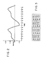
- Figure 2 shows a vibration signal, acquired while the part is operating within its normal speed range, varying between +1.5 and -1 volts with a regular periodic behavior.
- Figure 2 shows how 16 data points can be sampled at equally spaced time intervals.
- the data points acquired by converter 111 can easily be digitized to be in terms of voltage monitored at each respective data point as shown in Figure 3.
- the input signal can be transformed to the frequency domain using a fast Fourier or equivalent process. Output of the frequency domain data would appear as a plot of amplitude versus frequency depicting those frequencies and respective magnitudes that were present in the original data sample.
- the data shown in Figure 4 is the original data transformed to the frequency domain and normalized by rpm.
- the process exhibited in Figures 2-4 is also carried out during coastdown and the results are shown in Figure 5.
- Figure 6 is the resultant data obtained by subtracting plot 5 from plot 4.
- Figure 7 presents the resulting operating data trace free of the influence of runout. If both X and Y vibration monitors are present, runout free orbits can easily be calculated by using the above technique.
- Figure 7 is obtained by performing an inverse transform on the data shown in Figures 4 and 6.
- the dotted line is time domain data of Figure 4 including the runout data
- the solid line is the data of Figure 6 corrected for the runout data.
- the vector nulling procedure comprises acquiring a data sample during coastdown. Using a tracking filter, the rotating speed amplitude and phase components are determined. These components are memorized and later subtracted from operating data electronically. In most common implementations of this technique, the compensation is limited to correction of the running speed component only, and therefore any of the other frequency data present in the runout is ignored. Therefore, with this method one can tell if there is a problem with the rotating part, but one has only limited information about the nature of such problem.
- the second common method of runout correction is digital time domain runout correction. This procedure comprises acquiring a data set during coastdown and digitizing it into a series of discrete points per shaft revolution. The data set obtained is stored in memory and later subtracted from data sets acquired during operation. Using this time domain method with data such as in Figure 2, it would be necessary to correct each individual data point by subtracing the correct amount of runout as measured during coastdown. This is extremely time consuming and cumbersome.
- the three major differences between the conventional time domain method and the frequency domain method of this invention are (1) intended end product, (2) number of data manipulations, and (3) signal to noise quality.
- the frequency domain method of this invention is particularly advantageous in situations where it is desired that the data be viewed in spectral format, such as condition monitoring of rotating machinery.
- the frequency domain method of this invention requires considerably fewer data manipulations.
- Time domain techniques require that the runout correction be performed on each data sample prior to continuation of the data manipulation process. Consequently, a typical data assemblage with 64 averages would require 64 runout subtraction processes for each of the data points (512 typical).
- a typical vibration spectrum is usually comprised of a few discrete frequencies containing a contribution with the remaining frequencies void of any significant energy.
- a sample vibration spectrum was presented as Figure 6. There are three significant frequencies present. Using the frequency domain method of this invention requires that only three runout subtractions be performed. If an averaging technique is employed, the runout subtraction is performed subsequent to the averaging process and still only three subtractions are required.
- a third advantage to the frequency domain method of this invention involves averaging the runout data to achieve a better signal to noise ratio. Since the time domain method subtracts the runout waveform from each sample, any error present in the runout will be present in the corrected data and cannot be averaged out. By averaging the runout data in the frequency domain, a better quality signal can be obtained.
- the savings of computational time and ease of computation using the new technique of this invention enables the creation of a superior machine protection procedure and permits better vibration analysis to be performed than using previously available techniques.
Landscapes
- Physics & Mathematics (AREA)
- General Physics & Mathematics (AREA)
- Measurement Of Mechanical Vibrations Or Ultrasonic Waves (AREA)
- Testing Of Devices, Machine Parts, Or Other Structures Thereof (AREA)
Applications Claiming Priority (2)
| Application Number | Priority Date | Filing Date | Title |
|---|---|---|---|
| US86555786A | 1986-05-21 | 1986-05-21 | |
| US865557 | 1986-05-21 |
Publications (2)
| Publication Number | Publication Date |
|---|---|
| EP0246637A2 true EP0246637A2 (de) | 1987-11-25 |
| EP0246637A3 EP0246637A3 (de) | 1988-07-20 |
Family
ID=25345772
Family Applications (1)
| Application Number | Title | Priority Date | Filing Date |
|---|---|---|---|
| EP87107353A Ceased EP0246637A3 (de) | 1986-05-21 | 1987-05-20 | Verfahren zur Überwachung von Schwingungen in rotierenden Geräten |
Country Status (3)
| Country | Link |
|---|---|
| EP (1) | EP0246637A3 (de) |
| KR (1) | KR920004647B1 (de) |
| BR (1) | BR8702534A (de) |
Cited By (7)
| Publication number | Priority date | Publication date | Assignee | Title |
|---|---|---|---|---|
| WO1994000741A1 (fr) * | 1992-06-30 | 1994-01-06 | Valery Borisovich Kitaev | Dispositif de diagnostic de mecanisme a action cyclique |
| ES2051199A2 (es) * | 1991-01-30 | 1994-06-01 | Westinghouse Electric Corp | Sistema y metodo para vigilar la vibracion sincronica de alabes. |
| WO1998009140A1 (de) * | 1996-08-27 | 1998-03-05 | Prüftechnik Dieter Busch AG | Verfahren zum überwachen schwingungserregter aggregate |
| EP0902263A1 (de) * | 1997-09-15 | 1999-03-17 | Total Raffinage Distribution S.A. | Verfahren und Vorrichtung zur Bestimmung von Schwingungen des Rotors einer Drehmaschine |
| RU2221997C1 (ru) * | 2002-04-19 | 2004-01-20 | Автономная некоммерческая организация научно-технологический парк Оренбургского государственного университета | Стенд для испытания зубчатых передач по схеме замкнутого контура |
| RU2224223C1 (ru) * | 2002-09-09 | 2004-02-20 | Институт надежности машин НАН Беларуси | Устройство для виброакустической диагностики передач зацеплением |
| WO2022245354A1 (en) * | 2021-05-20 | 2022-11-24 | Machine Saver, Inc. | Vibration detection and correction system |
Families Citing this family (1)
| Publication number | Priority date | Publication date | Assignee | Title |
|---|---|---|---|---|
| KR101685078B1 (ko) * | 2014-11-27 | 2016-12-12 | 노바센(주) | 고속응답 특성을 갖는 초고속 회전체용 진동센서 |
Family Cites Families (1)
| Publication number | Priority date | Publication date | Assignee | Title |
|---|---|---|---|---|
| NL7416808A (nl) * | 1974-03-28 | 1975-09-30 | Reutlinger Wolf Dieter | Werkwijze voor tellingsmetingen aan roterende machinedelen en inrichting voor het uitvoeren van die werkwijze. |
-
1987
- 1987-05-19 BR BR8702534A patent/BR8702534A/pt unknown
- 1987-05-20 KR KR1019870004983A patent/KR920004647B1/ko not_active Expired
- 1987-05-20 EP EP87107353A patent/EP0246637A3/de not_active Ceased
Cited By (9)
| Publication number | Priority date | Publication date | Assignee | Title |
|---|---|---|---|---|
| ES2051199A2 (es) * | 1991-01-30 | 1994-06-01 | Westinghouse Electric Corp | Sistema y metodo para vigilar la vibracion sincronica de alabes. |
| WO1994000741A1 (fr) * | 1992-06-30 | 1994-01-06 | Valery Borisovich Kitaev | Dispositif de diagnostic de mecanisme a action cyclique |
| WO1998009140A1 (de) * | 1996-08-27 | 1998-03-05 | Prüftechnik Dieter Busch AG | Verfahren zum überwachen schwingungserregter aggregate |
| EP0902263A1 (de) * | 1997-09-15 | 1999-03-17 | Total Raffinage Distribution S.A. | Verfahren und Vorrichtung zur Bestimmung von Schwingungen des Rotors einer Drehmaschine |
| FR2768509A1 (fr) * | 1997-09-15 | 1999-03-19 | Total Raffinage Distribution | Procede de determination des vibrations du rotor d'une machine tournante, equipement pour machine tournante et machine tournante equipee |
| US6158286A (en) * | 1997-09-15 | 2000-12-12 | Total Raffianage Distribution S.A. | Process and devices for the determination of the vibrations of the rotor of a rotary machine |
| RU2221997C1 (ru) * | 2002-04-19 | 2004-01-20 | Автономная некоммерческая организация научно-технологический парк Оренбургского государственного университета | Стенд для испытания зубчатых передач по схеме замкнутого контура |
| RU2224223C1 (ru) * | 2002-09-09 | 2004-02-20 | Институт надежности машин НАН Беларуси | Устройство для виброакустической диагностики передач зацеплением |
| WO2022245354A1 (en) * | 2021-05-20 | 2022-11-24 | Machine Saver, Inc. | Vibration detection and correction system |
Also Published As
| Publication number | Publication date |
|---|---|
| BR8702534A (pt) | 1988-02-23 |
| KR920004647B1 (ko) | 1992-06-12 |
| KR870011459A (ko) | 1987-12-23 |
| EP0246637A3 (de) | 1988-07-20 |
Similar Documents
| Publication | Publication Date | Title |
|---|---|---|
| Fyfe et al. | Analysis of computed order tracking | |
| US5744723A (en) | Method for determining rotational speed from machine vibration data | |
| US5445028A (en) | Dynamic digital tracking filter | |
| Bechhoefer et al. | Processing for improved spectral analysis | |
| EP1021698B1 (de) | Dynamischer ungleichmässiger takt für wiederabtastung und verarbeitung von maschinensignalen | |
| US7031873B2 (en) | Virtual RPM sensor | |
| US6408696B1 (en) | Coherent phase line enhancer spectral analysis technique | |
| EP0776464B1 (de) | Verfahren zum bestimmen von resonanzinformation | |
| Andre et al. | Precision of the IAS monitoring system based on the elapsed time method in the spectral domain | |
| US4485678A (en) | Rotor diagnostic and balancing system | |
| US4608650A (en) | Imbalance measuring system and method | |
| US6263738B1 (en) | Vibration phasor monitoring system for rotating members | |
| US9551629B2 (en) | System for acquiring a vibratory signal of a rotary motor | |
| JPH09113416A (ja) | ころがり軸受の損傷診断方法 | |
| EP0246637A2 (de) | Verfahren zur Überwachung von Schwingungen in rotierenden Geräten | |
| CN111046541A (zh) | 发动机基频振动幅值随转速变化自适应求解方法与系统 | |
| Lopatinskaia et al. | Monitoring varying speed machinery vibrations—II recursive filters and angle domain | |
| US11898994B2 (en) | Waveform acquisition optimization | |
| CN117686232A (zh) | 一种燃气轮机振动基频实时提取方法、装置及存储介质 | |
| US20030172738A1 (en) | Process and device for processing of vibration measurements of a rotating machine rotor | |
| André et al. | Comparison between angular sampling and angular resampling methods applied on the vibration monitoring of a gear meshing in non stationary conditions | |
| CN116989885B (zh) | 一种含谐波和脉冲的轴承振动信号的时频表示方法及系统 | |
| RU2154813C1 (ru) | Способ диагностики работы двигателя | |
| JPH0733977B2 (ja) | 歯車異常診断装置 | |
| CN115683644B (zh) | 航空发动机双源拍振特征识别方法 |
Legal Events
| Date | Code | Title | Description |
|---|---|---|---|
| PUAI | Public reference made under article 153(3) epc to a published international application that has entered the european phase |
Free format text: ORIGINAL CODE: 0009012 |
|
| AK | Designated contracting states |
Kind code of ref document: A2 Designated state(s): AT BE CH DE ES FR GB IT LI LU NL SE |
|
| RHK1 | Main classification (correction) |
Ipc: G01H 1/00 |
|
| PUAL | Search report despatched |
Free format text: ORIGINAL CODE: 0009013 |
|
| AK | Designated contracting states |
Kind code of ref document: A3 Designated state(s): AT BE CH DE ES FR GB IT LI LU NL SE |
|
| 17P | Request for examination filed |
Effective date: 19880726 |
|
| 17Q | First examination report despatched |
Effective date: 19890822 |
|
| STAA | Information on the status of an ep patent application or granted ep patent |
Free format text: STATUS: THE APPLICATION HAS BEEN REFUSED |
|
| 18R | Application refused |
Effective date: 19900915 |
|
| RIN1 | Information on inventor provided before grant (corrected) |
Inventor name: BRAUN, FREDERICK WILLIAM Inventor name: BRADBURY, EUGENE RICHARD |