EP0246636A2 - Apparatus for fusion-splicing a pair of polarization maintaining optical fibers - Google Patents
Apparatus for fusion-splicing a pair of polarization maintaining optical fibers Download PDFInfo
- Publication number
- EP0246636A2 EP0246636A2 EP87107350A EP87107350A EP0246636A2 EP 0246636 A2 EP0246636 A2 EP 0246636A2 EP 87107350 A EP87107350 A EP 87107350A EP 87107350 A EP87107350 A EP 87107350A EP 0246636 A2 EP0246636 A2 EP 0246636A2
- Authority
- EP
- European Patent Office
- Prior art keywords
- optical fibers
- pair
- fusion
- splicing
- fiber
- Prior art date
- Legal status (The legal status is an assumption and is not a legal conclusion. Google has not performed a legal analysis and makes no representation as to the accuracy of the status listed.)
- Granted
Links
Images


Classifications
-
- G—PHYSICS
- G02—OPTICS
- G02B—OPTICAL ELEMENTS, SYSTEMS OR APPARATUS
- G02B6/00—Light guides; Structural details of arrangements comprising light guides and other optical elements, e.g. couplings
- G02B6/24—Coupling light guides
- G02B6/255—Splicing of light guides, e.g. by fusion or bonding
- G02B6/2555—Alignment or adjustment devices for aligning prior to splicing
-
- G—PHYSICS
- G02—OPTICS
- G02B—OPTICAL ELEMENTS, SYSTEMS OR APPARATUS
- G02B6/00—Light guides; Structural details of arrangements comprising light guides and other optical elements, e.g. couplings
- G02B6/24—Coupling light guides
- G02B6/255—Splicing of light guides, e.g. by fusion or bonding
- G02B6/2551—Splicing of light guides, e.g. by fusion or bonding using thermal methods, e.g. fusion welding by arc discharge, laser beam, plasma torch
-
- G—PHYSICS
- G02—OPTICS
- G02B—OPTICAL ELEMENTS, SYSTEMS OR APPARATUS
- G02B6/00—Light guides; Structural details of arrangements comprising light guides and other optical elements, e.g. couplings
- G02B6/24—Coupling light guides
- G02B6/36—Mechanical coupling means
- G02B6/38—Mechanical coupling means having fibre to fibre mating means
- G02B6/3801—Permanent connections, i.e. wherein fibres are kept aligned by mechanical means
- G02B6/3803—Adjustment or alignment devices for alignment prior to splicing
- G02B6/3805—Adjustment or alignment devices for alignment prior to splicing with a fibre-supporting member inclined to the bottom surface of the alignment means
Definitions
- This invention relates to an apparatus for fusion-splicing a pair of polarization maintaining optical fibers and, more particularly, to an improvement on a mechanism for aligning a pain of polarization maintaining optical fibers with each other when the optical fibers are fusion-spliced.
- the optical fibers In aligning a pair of polarization maintaining optical fibers to be fusion-spliced with each other, the optical fibers must be moved not only in X and Y directions (those are oriented orthogonally on the cross sections of the optical fibers), but also in the circumferential direction.
- each of a pair of polarization maintaining optical fibers comprises cores l4, cladding region l6, and stress-applying parts l8.
- Figs. l and 2 only show the portions of the optical fibers, which are adjacent to the to-be-fusion-spliced end faces of the fibers. These figures show the cross sections of the fibers, thereby to facilitate the understand of the structure of the optical fibers, although actually they cannot be seen since the fibers are positioned face-to-face.
- the remaining portion of each fiber is covered with sheath laid around and in contact with cladding region l6.
- the exposed portion of each fiber where the sheath is peeled off will be referred to as an exposed fiber portion l2.
- the portion covered with sheath will be referred to as a sheathed fiber portion ll (not shown in Figs. l and 2).
- the entire optical fiber will be referred to as optical fiber l0.
- stress-applying parts l8 of one of the fibers are, as shown in Fig. l, aligned with those of the other fiber, or are, as shown in Fig. 2, displaced in maximum from those of the other fiber.
- the optical fibers must be moved in X and Y directions so as to obtain the axial alignment of the fibers. These directions are orthogonally oriented each other on the cross sections of the fibers.
- the fibers are turned by angle ⁇ in circumferential direction around the axes of the fibers, i.e., Z-axis to align the stress-applying parts l8 of the fibers or to displace the parts in maximum.
- an object of this invention is to provide an apparatus for fusion-splicing a pair of polarization maintaining optical fibers, in which a mechanism for aligning the fibers is improved.
- an apparatus for fusion-splicing a pair of polarization maintaining optical fibers comprising: rotating means including a first mechanical means for clamping one of a pair of polarization maintaining optical fibers, and for manually rotating said clamped optical fiber about its axis, a second mechanical means for clamping the other polarization maintaining optical fiber, and for rotating said clamped optical fiber about its axis by a motor, whereby said pair of the optical fibers are aligned with each other; rotation control means for controlling the rotation of said motor so as to vary the extinction ratio of light emitted from the light emitting end of said pair of optical fibers; and means for fusion-splicing said pair of optical fibers by an arc discharge after said fibers are aligned with each other.
- an apparatus for fusion-splicing a pair of polarization maintaining optical fibers comprising: stopper means to which the end faces of a pair of polarization maintaining optical fibers abut, said stopper means being provided with mirror means for reflecting an image of the end faces of said pair of optical fibers when said mirror means is set at the place where said pair of optical fibers are made abut at the end faces; a microscope for observing via said mirror means the alignment of said pair of optical fibers at the end faces; means for setting said mirror means at the highest position higher than the end face abutting position, said end face abutting position, and the lowest position lower than said end face abutting position; rotating means for clamping said pair of optical fibers, and rotating said pair of clamped optical fibers about their axes manually, whereby said pair of optical fibers are aligned with each other; and means for fusion-splicing said pair of aligned optical fibers by an arc discharge.
- an apparatus for fusion-splicing a pair of polarization maintaining optical fibers comprising: fiber clamps and sheath clamps for respectively clamping the exposed fiber portions and the covered fiber portions of a pair of polarization maintaining optical fibers, said fiber clamps and sheath clamps being interlocked in operation; sheath clamp releasing means for releasing said sheath clamps from clamping of said covered fiber portions, while said exposed fiber portions is being clamped by said fiber clamps; rotating means for clamping said pair of optical fibers and rotating said clamped optical fibers about their axes, whereby said pair of optical fibers are aligned with each other; and means for fusion-splicing said pair of aligned optical fibers by an arc discharge.
- an apparatus for fusion-splicing a pair of polarization maintaining optical fibers comprising: rotating means for clamping a pair of polarization maintaining optical fibers and rotating said clamped optical fibers about their axes, whereby said pair of optical fibers are aligned with each other; means for fusion-splicing said pair of aligned optical fibers by an arc discharge; and twist preventing means including an arm removably coupled with the fusion-splicing apparatus and clamp means for clamping said pair of optical fibers when said arm is coupled with the fusion-splicing apparatus, said clamp means extending from each end of said arm, whereby, when said pair of optical fibers coupled with twist preventing means are removed from the fusion-splicing apparatus, no twist is generated to said pair of optical fibers.
- the exposed fiber portions l2 of a pair of polarization maintaining optical fibers l0 are placed in the V-grooves of a pair of V-groove blocks 20.
- the exposed fiber portions l2 placed in the V-grooves are respectively clamped by a pair of fiber clamps 22 (shown in Fig. 5, but omitted in Fig. 4).
- Fiber clamp 22 is provided at one end of fiber clamp arm 23.
- a pair of sheathed or covered fiber portions ll of optical fibers l0 are placed on a pair of support blocks 24, respectively.
- the covered fiber portions ll are clamped by a pair of sheath clamps 26 (shown in Fig. 5, but omitted in Fig. 4).
- Sheath clamp 26 is provided at one end of sheath clamp arm l28.
- Fiber clamp arm 23 and sheath clamp arm l28 are mounted to the frame of the apparatus.
- Sheath clamp arm l28 can be swung at pin l3l.
- Fiber clamp arm 23 can also swung at a pin (not shown).
- Support blocks 24 can each be swung at pint 28 clockwise and counterclockwise as shown by arrow 30 in Fig. 5.
- Reference numeral 38 designates a pair of electrodes for generating arc discharge therebetween so that optical fibers l0 may be fusion-spliced.
- Reference numeral 39 designates a stopper to which the optical fibers abut.
- a pair of rotating mechanisms 44A and 44B are provided for rotating the optical fibers.
- the upper portion 42 of bracket 40 of each of rotating mechanisms 44A and 44B is slightly and forwardly slanted. Brackets 42 hold arms 52 and 54 while these arms is slanted slightly and forwardly.
- the rotating mechanism 44A will be described.
- the tubular portion 46 of the base is rotatably supported by the forwardly slanted upper portion 42.
- Tubular portion 46 is manually rotatable by dial 48 formed integral with portion 46.
- Groove 50 is formed in tubular portion 46 and dial 48, as shown in Figs. 4 and 6. The lower end of groove 50 reaches the axes of tubular portion 46 and dial 48. Groove 43 is formed in bracket 40. Grooves 43 and 50 are aligned with each other. Then, if the optical fiber is placed in the grooves, the optical fiber is located at the center of tubular portion 46 and bracket 40. Under this condition, if tubular portion 46 and dial 48 are rotated, the optical fiber is not moved, and therefore is not twisted.
- Fixed arm 52 and movable arm 54 projects slightly downwardly from tubular portion 46.
- Fixed arm 52 is fixed at the tubular portion 46.
- Movable arm 54 is supported at the rear end by pin 56.
- Spring 58 and cam 60 cooperate to swing movable arm 54 at pin 56.
- the fixed portion 62 of clamp 6l is provided at one end of fixed arm 52, and the movable portion 64 of clamp 6l is provided at one end of movable arm 54.
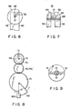
- Fixed portion 62 and movable portion 64 are semicircular in cross section, as well illustrated in Fig. 7. When movable arm 54 is swung to be in contact with fixed arm 52, arms 52 and 54 are shaped tubular. V groove 66 is formed in fixed portion 62.
- Fiber guide 68 is provided before rotating clamp 6l. Fiber guide 68 is fixed to only the fixed arm 52. Optical fiber l0 is placed on fixed arm 52, cam 60 is rotated to make movable portion 64 contact with fixed portion 62, and rotating clamp 6l is closed. Under this condition, optical fiber l0 is held in a clamped state. In the clamped state, if dial 48 is rotated, the clamp 6l clamping optical fiber l0 is rotated to cause optical fiber l0 to rotate around its axis.
- the rotating mechanism 44B will now be described.
- Rotating mechanism 44B is substantially the same as the mechanism 44A. Only the different portion of this mechanism 44B from mechanism 44A will be described.
- gear 70 is used in place of dial 48.
- the dial is rotated by motor 72 through a train of gears 74, 76 and 78.
- Gears 76 and 78 are formed integral with each other, and are rotatable about shaft 33.
- An amount of rotation of motor 72 is controlled by the combination of detector 92 and control circuit 94.
- Detector 92 detects optical power at the light emitting end of the optical fibers (one end of the fiber at the right in Figs. 4 and 5).
- gear 70 is pulled by tension spring 82 through wire 80 in the direction opposite to the rotating direction of motor 72.
- tension spring 82 To automatically obtain the optimum angle, it is necessary to lessen the backlash of gear 70 in the forward and reversed directions. In this instance, the backlash is substantially zero by tension spring 82, and the angle can be finely adjusted in the unit of ⁇ 0.5 degrees.
- sensor plate 84 is mounted to gear 74, as well illustrated in Fig. 8.
- the sensor plate is a fan plate whose spread angle ⁇ is 45 degrees.
- the plate is swung clockwise or counterclockwise according to the rotating direction of gear 74.
- This critical point of sensor plate 84 is the start point of the motor operation.
- the groove 7l of gear 70 and tubular portion 46 is opened upwardly (Fig. 8) to allow the optical fiber, if the fiber is set therein, to be picked up from the groove. If groove 7l is opened horizontally, the groove of bracket 40 is not aligned with its extension and, therefore, it is impossible to pick up the optical fiber.
- sensor plate 84 is turned clockwise and is stopped by an appropriate brake means (not shown) as photo sensor device 86b is turned off.
- sensor plate 84 When sensor plate 84 is swung clockwise, sensor plate 84 interrupts the light beam from photo sensor 86. In this case, therefore, sensor plate 84 is turned counterclockwise, and is stopped by an appropriate control means (not shown) as the photo sensor device 86b of photo sensor 86 is turned on.
- Rotating mechanism 44B, motor 72 and the train including gears 74, 76, 78 and 70 are placed on frame 88 of a drive mechanism and movable in z-axis.
- Optical fiber l0 is set on rotating mechanisms 44A and 44B and blocks 20 and 24. The fiber is held by fiber clamp 22 and sheath clamp 26, and rotating clamp 6l driven by cam 60.
- Fig. 9 shows an image of the end faces of the exposed fiber portions l2, which is reflected in the mirror at the end of stopper 39 and monitored through microscope 90. This monitoring of the image is not essential to this embodiment, and hence no further explanation thereof will be given.
- a first step an operator manually turns dial 48 in rotating mechanism 44A so that stress-applying parts l8 of one of the fibers are disposed orthogonal to those of the other fiber or displaced in maximum from those of the other fiber. This operation is done while observing the image at the end faces through the microscope.
- the optical fibers are subjected to a known automatic alignment in X and Y directions.
- the fibers are subjected to the automatic alignment in ⁇ direction, i.e. the circumferential direction. This alignment is performed as follows. When, as shown in Fig.
- stress-applying parts l8 of one of the fibers are aligned with those of the other fiber, or as shown in Fig. 2, shifted or displaced angularly in maximum, the extinction ratio of the light emitted from the light emitting end of the optical fibers is maximized.
- the stress-applying parts of the fibers are shifted at 45 degrees, the extinction ratio is minimized.
- the optical power changes. The change of optical power is detected by beam detector 92. The output of detector 92 is fed back to control circuit 94 to control the rotation of motor 72.
- one of the rotating mechanisms is under control of the motor.
- the motor is automatically controlled depending on the amount of the light emitted from the light emitting end. This realizes an exact adjustment of the optical fibers in the circumferential or angular direction. As a result, the remarkable improvements on the adjustment work can be obtained.
- the extinction ratio is minimum when the stress-applying parts of the fibers are aligned or displaced in maximum. Therefore, it can not be determined only by the amount of the light from the light emitting end of the fibers whether the stress-applying parts are aligned or displaced in maximum.
- a mirror is provided at the top of stopper 39, for observing images at both end faces of a pair of polarization maintaining optical fibers. Further provided is means for controlling the height of the top of stopper 39 at three steps, i.e., lowest, medium and highest positions.
- the second embodiment by the combination of the mirror and the height control means, an operator can manually make coarse angular adjustment of the fiber alignment, while observing the end face images of fibers through microscope 90. Therefore, it can be ascertained whether the stress-applying parts are aligned or displaced. Moreover, the time required for the fine adjustment can be reduced when compared with the case by only the fine adjustment.
- the upper end portion of stopper 39 has a plate member l02 with a predetermined width, whose tip is shaped like a right-angle isosceles.
- Each of the rectangular planes constitutes a mirror l04.
- first solenoid ll2 is fixed to the frame ll4 of the apparatus, and is used to raise yoke ll6 by a predetermined height.
- Second solenoid ll8 is fixed to yoke ll6, and is to raise stopper 39 by a predetermined height.
- Stopper 39 is at the lowest position when both solenoids ll2 and ll8 are disable. It is at the medium position when only solenoid ll8 is operated. It is at the highest position when both solenoids are operated. Alternatively, stopper 39 may be moved up and down using an appropriate drive means, for example, the motor and wire combination.
- a system comprising two levers energized by two solenoids may be used to move stopper 39.
- the solenoids When the solenoids are disable, the levers do not move and the stopper is set at the lowest position.
- the first solenoid When the first solenoid is enable, the first lever moves and the stopper is set at the medium position.
- the solenoids When the solenoids are enable, the levers move and the stopper is set at the highest position.
- Stopper 39 is first set at the highest position, as shown in Fig. l2A.
- the highest position is slightly higher than the position where the end faces of the optical fibers are made in contact with each other. Under this condition, optical fibers l0 are set in place and held by fiber clamp 22 and sheath clamp 26.
- optical fibers l0 are moved to be made to abut stopper 39 at the end faces of the fibers.
- Stopper 39 is now lowered to the lowest position, as shown in Fig. l2B. This position is at least below the abutting place of optical fibers l0. A weak arc discharge is momentarily applied to the end faces of fibers l2 to heat them at high temperature. With the momentary discharge, dust attached to the end faces is burned. Moreover, the exposed portions of the stress-applying parts are sputtered due to the difference of the melting points of the cladding region and the stress-applying parts. Therefore, stress-applying parts l8 can be clearly recognized.
- Stopper 39 is raised to the medium position, as shown in Fig. l2C.
- the medium position coincides with the abutting place of optical fibers.
- the mirror l04 at the top of stopper 39 reflects the image of the end faces of optical fibers l0.
- Mirror l04 directs the optical information of the end faces of the fibers toward microscope 90. Therefore, optical fibers l0 is clamped by rotating clamp 6l.
- Dial 46 is manually turned to align stress-applying parts pairs l8 of the fibers as shown in Fig. l or rotate one of the fibers by 90° from the other, as shown in Fig. 2.
- Stopper 39 is lowered to the lowest position, again. At this position, optical fibers l2 are subjected to the automatic fine adjustments in z-, x- and y-directions and the circumferential direction. Thereafter, the fibers are fusion-spliced through the arc discharge via the electrodes (not shown).
- this embodiment for the coarse adjustment for the alignment of the optical fibers, the image of the end faces of the fibers is reflected by the mirror at the top of the stopper, and the image is observed through the microscope. While, the fine adjustment of the optical fibers is performed by the motor drive. In this way, this embodiment employs two steps for the alignment of the optical fibers, the coarse adjustment and the fine adjustment. This reduces considerably the time taken for the alignment when compared with the case using only the automatic alignment.
- Sheath clamp 26 is needed for feeding the optical fibers l0, however, impedes the rotation of optical fibers l0 by rotating mechanisms 44A and 44B. This impedance hinders the fine adjustment by turning optical fibers l0.
- the rotating clamp 6l is generally designed for the optical fiber whose sheathed fiber portion has a 0.9 mm outer diameter.
- heat shrinkable tubes or split tubes are applied to the fibers to obtain the optical fibers of 0.9 mm diameter.
- the optical fiber covered with such tube is poor in circularness, and this fact hinders the smooth turn of the fibers.
- a third embodiment of this invention which is designed for solving the problem, will be shown in Figs. l4 and l5.
- sheath clamp 26 is released from being held, while keeping the clamping of fiber clamp 22. This feature allows the adjustment for alignment of the optical fibers to be well done free from the above-mentioned problem.
- reference numeral l22 designates a part of frame ll4 of the apparatus, and is substantially V-shaped as viewed from above.
- Lever l24 of substantially V-shape is swung about pin l26.
- Sheath clamp arm l28 can be swung about pin l3l in an interlocking manner as shown in Fig. l5.
- Fiber clamp 22 and sheath clamp 26 are held by springs (not shown). In this case, the former is slightly held, but the latter strongly held.
- Projection l30 is formed at the top of the arm l28 of sheath clamp 26.
- the sheath clamp arm is mounted to the frame of the apparatus and can be swung at pin l3l.
- lever l24 is set under projection l30, as well illustrated in Fig. l5.
- Square cut-away portion l34 is formed at the lower end portion of frame portion l22.
- Lock lever l36 is inserted into the cut-away portion and mounted to the frame portion by means of pin l38. Lock lever l36 can be swung around pin l38. Spring l40 biases lock lever l36 backwardly.
- Hook l44 is provided on the rear side of lock lever l36.
- Horizontal bar l46 of lever l24 has surface l48 slanted downwardly. When lever l24 is pulled down, the hook l44 of lock lever l36 is placed in the space defined by the slanted surface.
- FIG. l6 A fourth embodiment of this invention is shown in Figs. l6 and l7.
- rib l82 is formed on almost half of the top surface of support block 24. Rib l82 provides a stepped portion.
- Groove l84 is formed in rib l82, as well illustrated in fig. l7. The groove allows optical fiber l0 to smoothly be set in place. The width of groove l84 is narrower than that of sheath clamp 26.
- Dial 32 is turned and swash plate cam 34 is then turned.
- support block 24 is pushed by spindle 36 and turned in the direction of arrow l86.
- sheath clamp 26 is placed on the rib l82 and clamp 26 is released from its clamping state.
- the sheath clamp in the alignment in the circumferential direction, the sheath clamp is released from its clamping state. Therefore, the impedance for the turning of the fibers is little, realizing an exact alignment of optical fibers.
- the spliced fiber is removed from the apparatus, and the spliced part of the fiber is reinforced.
- fiber clamp 22, sheath clamp 26 and rotatable clamp 6l are all removed. At this time, twisting force is directly applied to the spliced part of the fiber.
- a polarization maintaining optical fiber is sensitive to the twist. It is, therefore, preferable to apply the reinforcement to the spliced part of the optical fiber with less twist.
- twist preventing unit 40 is attached to the fusion-splicing apparatus which clamps the spliced optical fiber to lock the fiber against its turn. This will be described referring to Figs. l8 and l9.
- twist preventing unit 240 is comprised of arm 242 and clamp means 256.
- Arm 242 is a bar shaped square in cross section. It can be divided into two sections, right and left halves 244 and 243.
- Coupling bar 246 is projected from the end face of the left half section 243. This coupling bar 246 is slidably fitted into the end portion of the right half section 244. Pin 248 of coupling bar 246 and elongated hole 250 of the right half section 244 cooperate to limit the sliding range of these sections.
- Clamp means 256 are planted in both ends of arm 242.
- Each of clamp means 256 contains circular rod like shaft 258. This shaft is fixed at the base to arm 242, and has a U-shaped groove 260 at the top.
- Optical fiber is fit in groove 260.
- Sleeve 262 is slidably fitted around shaft 258.
- the base of sleeve 262 is slidably fitted in concave 24l of arm 242. It is always biased to the left by spring 264 as shown in Fig. l9.
- Pin 266 is mounted to shaft 258.
- Pin 266 is coupled with elongated hole 268 of sleeve 262 to prevent the sleeve from slipping off and to limit the movement of sleeve 262.
- Knob 270 is fixed to sleeve 262.
- sleeve 262 In use, sleeve 262 is moved toward arm 242 by a finger as shown in Fig. l9. Optical fiber l0 is inserted into groove 60, and the finger is detached from it. Then, sleeve 262 is automatically returned to its original place by spring 264. In turn, optical fiber l0 is pushed against the side wall of groove 260 for clamping. Under this condition, the fiber is locked against its turn.
- a couple of circular rods 254 are upstanding on the upper surface of frame ll4 of the apparatus, while spaced by a predetermined distance.
- the rods are inserted into elongated holes 252 of arm 242 to removably attach the twist preventing unit to the frame ll4 of the apparatus.
- the fiber portion at the outside of the spliced part of the fiber is clamped by the twist preventing unit, and then the fiber is removed for the reinforcement. Therefore, the twist problems can be solved successfully.
- the present invention provides an apparatus for fusion-splicing a pair of polarization maintaining optical fibers, which can remarkably improve the alignment of optical fibers.
Landscapes
- Physics & Mathematics (AREA)
- Engineering & Computer Science (AREA)
- Plasma & Fusion (AREA)
- General Physics & Mathematics (AREA)
- Optics & Photonics (AREA)
- Mechanical Coupling Of Light Guides (AREA)
Abstract
Description
- This invention relates to an apparatus for fusion-splicing a pair of polarization maintaining optical fibers and, more particularly, to an improvement on a mechanism for aligning a pain of polarization maintaining optical fibers with each other when the optical fibers are fusion-spliced.
- In aligning a pair of polarization maintaining optical fibers to be fusion-spliced with each other, the optical fibers must be moved not only in X and Y directions (those are oriented orthogonally on the cross sections of the optical fibers), but also in the circumferential direction.
- As shown in Figs. l and 2, each of a pair of polarization maintaining optical fibers comprises cores l4, cladding region l6, and stress-applying parts l8. Figs. l and 2 only show the portions of the optical fibers, which are adjacent to the to-be-fusion-spliced end faces of the fibers. These figures show the cross sections of the fibers, thereby to facilitate the understand of the structure of the optical fibers, although actually they cannot be seen since the fibers are positioned face-to-face. The remaining portion of each fiber is covered with sheath laid around and in contact with cladding region l6. The exposed portion of each fiber where the sheath is peeled off will be referred to as an exposed fiber portion l2. The portion covered with sheath will be referred to as a sheathed fiber portion ll (not shown in Figs. l and 2). The entire optical fiber will be referred to as optical fiber l0.
- In aligning a pair of polarization maintaining optical fibers with each other, in order to minimize the extinction ratio, stress-applying parts l8 of one of the fibers are, as shown in Fig. l, aligned with those of the other fiber, or are, as shown in Fig. 2, displaced in maximum from those of the other fiber.
- In both cases, the optical fibers must be moved in X and Y directions so as to obtain the axial alignment of the fibers. These directions are orthogonally oriented each other on the cross sections of the fibers.
- Further, the fibers are turned by angle ϑ in circumferential direction around the axes of the fibers, i.e., Z-axis to align the stress-applying parts l8 of the fibers or to displace the parts in maximum.
- Practically, however, it is very difficult to turn the optical fibers finely in the circumferential direction so that the stress-applying parts may be aligned or displaced in maximum.
- Accordingly, an object of this invention is to provide an apparatus for fusion-splicing a pair of polarization maintaining optical fibers, in which a mechanism for aligning the fibers is improved.
- According to the invention, there is provided an apparatus for fusion-splicing a pair of polarization maintaining optical fibers, comprising:
rotating means including a first mechanical means for clamping one of a pair of polarization maintaining optical fibers, and for manually rotating said clamped optical fiber about its axis, a second mechanical means for clamping the other polarization maintaining optical fiber, and for rotating said clamped optical fiber about its axis by a motor, whereby said pair of the optical fibers are aligned with each other;
rotation control means for controlling the rotation of said motor so as to vary the extinction ratio of light emitted from the light emitting end of said pair of optical fibers; and
means for fusion-splicing said pair of optical fibers by an arc discharge after said fibers are aligned with each other. - According to the invention, there is further provided an apparatus for fusion-splicing a pair of polarization maintaining optical fibers, comprising:
stopper means to which the end faces of a pair of polarization maintaining optical fibers abut, said stopper means being provided with mirror means for reflecting an image of the end faces of said pair of optical fibers when said mirror means is set at the place where said pair of optical fibers are made abut at the end faces;
a microscope for observing via said mirror means the alignment of said pair of optical fibers at the end faces;
means for setting said mirror means at the highest position higher than the end face abutting position, said end face abutting position, and the lowest position lower than said end face abutting position;
rotating means for clamping said pair of optical fibers, and rotating said pair of clamped optical fibers about their axes manually, whereby said pair of optical fibers are aligned with each other; and
means for fusion-splicing said pair of aligned optical fibers by an arc discharge. - According to the invention, there is still further provided an apparatus for fusion-splicing a pair of polarization maintaining optical fibers comprising:
fiber clamps and sheath clamps for respectively clamping the exposed fiber portions and the covered fiber portions of a pair of polarization maintaining optical fibers, said fiber clamps and sheath clamps being interlocked in operation;
sheath clamp releasing means for releasing said sheath clamps from clamping of said covered fiber portions, while said exposed fiber portions is being clamped by said fiber clamps;
rotating means for clamping said pair of optical fibers and rotating said clamped optical fibers about their axes, whereby said pair of optical fibers are aligned with each other; and
means for fusion-splicing said pair of aligned optical fibers by an arc discharge. - According to the invention, there is yet further provided an apparatus for fusion-splicing a pair of polarization maintaining optical fibers comprising:
rotating means for clamping a pair of polarization maintaining optical fibers and rotating said clamped optical fibers about their axes, whereby said pair of optical fibers are aligned with each other;
means for fusion-splicing said pair of aligned optical fibers by an arc discharge; and
twist preventing means including an arm removably coupled with the fusion-splicing apparatus and clamp means for clamping said pair of optical fibers when said arm is coupled with the fusion-splicing apparatus, said clamp means extending from each end of said arm, whereby, when said pair of optical fibers coupled with twist preventing means are removed from the fusion-splicing apparatus, no twist is generated to said pair of optical fibers. - This invention can be more fully understood from the following detailed description when taken in conjunction with the accompanying drawings, in which:
- Fig. l shows in cross sectional form a pair of polarization maintaining optical fibers, in which the stress-applying parts of the fibers are aligned with each other;
- Fig. 2 shows in cross sectional form a pair of polarization maintaining optical fibers, in which the paired stress-applying parts of the fibers are displaced at the maximum angle (90 degrees) one from the other;
- Fig. 3 shows a diagram showing the directions in which the optical fibers are moved for alignment of the fibers;
- Fig. 4 shows a plan view of an apparatus for fusion-splicing optical fibers, according to an embodiment of the present invention;
- Fig. 5 shows a side view of the fusion-splicing apparatus of Fig. 4;
- Fig. 6 shows a side view taken on line VI-VI in Fig. 5, particularly illustrating a tubular portion and a dial;
- Fig. 7 shows a side view taken on line VII-VII in Fig. 5, particularly illustrating a rotatable clamp;
- Fig. 8 shows a side view of taken on line VIII-VIII in Fig. 5, illustrating particularly a motor, a gear train, and their associated portions;
- Fig. 9 shows a diagram illustrating an image of the end faces of a pair of polarization maintaining optical fibers to be fusion-spliced, when the end faces are observed by a microscope;
- Fig. l0 shows a longitudinal sectional view of a fusion-splicing apparatus according to another embodiment of this invention;
- Fig. ll shows a perspective view of the top end of a stopper used in the embodiment of Fig. l0;
- Figs. l2A to l2C respectively show a diagram illustrating the stopper set at different positions;
- Fig. l3 shows a diagram of an image of the end faces of optical fibers when the end faces are observed by a microscope;
- Fig. l4 shows a plan view of a fusion-splicing apparatus according to yet another embodiment of this invention;
- Fig. l5 shows a side view of the fusion-splicing apparatus of Fig. l4;
- Fig. l6 shows a side view of the fusion-splicing apparatus according to a further embodiment of this invention;
- Fig. l7 shows a cross sectional view of a sheath clamp and a support block taken on line XVII-XVII in Fig. l6;
- Fig. l8 shows a plan view of a fusion-splicing apparatus according to another embodiment of this invention; and
- Fig. l9 shows a longitudinal sectional view of a clamp mechanism taken on line XIX-XIX in Fig. l8.
- Some specific embodiments of this invention will be described in detail referring to the accompanying drawings.
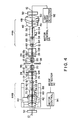
- As shown in Figs. 4 and 5, the exposed fiber portions l2 of a pair of polarization maintaining optical fibers l0 are placed in the V-grooves of a pair of V-groove blocks 20. The exposed fiber portions l2 placed in the V-grooves are respectively clamped by a pair of fiber clamps 22 (shown in Fig. 5, but omitted in Fig. 4).
Fiber clamp 22 is provided at one end offiber clamp arm 23. A pair of sheathed or covered fiber portions ll of optical fibers l0 are placed on a pair of support blocks 24, respectively. The covered fiber portions ll are clamped by a pair of sheath clamps 26 (shown in Fig. 5, but omitted in Fig. 4).Sheath clamp 26 is provided at one end of sheath clamp arm l28.Fiber clamp arm 23 and sheath clamp arm l28 are mounted to the frame of the apparatus. Sheath clamp arm l28 can be swung at pin l3l.Fiber clamp arm 23 can also swung at a pin (not shown). Support blocks 24 can each be swung atpint 28 clockwise and counterclockwise as shown byarrow 30 in Fig. 5. - When
dial 32 is manually turned,swash plate cam 34 is rotated andspindle 36 pushes the upper end portion ofsupport block 24, so thatsupport block 24 turns aroundpin 28 counterclockwise.Support block 24 is biased at the lower end portion by means of a spring. Then,support block 24 always receives the turning force in the clockwise direction. With this mechanism, optical fibers l0 are moved forwardly or backwardly in Z axis. -
Reference numeral 38 designates a pair of electrodes for generating arc discharge therebetween so that optical fibers l0 may be fusion-spliced.Reference numeral 39 designates a stopper to which the optical fibers abut. - A pair of
rotating mechanisms upper portion 42 ofbracket 40 of each ofrotating mechanisms Brackets 42 holdarms - The
rotating mechanism 44A will be described. - The
tubular portion 46 of the base is rotatably supported by the forwardly slantedupper portion 42.Tubular portion 46 is manually rotatable bydial 48 formed integral withportion 46. -
Groove 50 is formed intubular portion 46 anddial 48, as shown in Figs. 4 and 6. The lower end ofgroove 50 reaches the axes oftubular portion 46 anddial 48.Groove 43 is formed inbracket 40.Grooves tubular portion 46 andbracket 40. Under this condition, iftubular portion 46 and dial 48 are rotated, the optical fiber is not moved, and therefore is not twisted. - Fixed
arm 52 andmovable arm 54 projects slightly downwardly fromtubular portion 46. Fixedarm 52 is fixed at thetubular portion 46.Movable arm 54 is supported at the rear end bypin 56.Spring 58 andcam 60 cooperate to swingmovable arm 54 atpin 56. The fixedportion 62 of clamp 6l is provided at one end of fixedarm 52, and themovable portion 64 of clamp 6l is provided at one end ofmovable arm 54. Fixedportion 62 andmovable portion 64 are semicircular in cross section, as well illustrated in Fig. 7. Whenmovable arm 54 is swung to be in contact with fixedarm 52,arms V groove 66 is formed in fixedportion 62. -
Fiber guide 68 is provided before rotating clamp 6l.Fiber guide 68 is fixed to only the fixedarm 52. Optical fiber l0 is placed on fixedarm 52,cam 60 is rotated to makemovable portion 64 contact with fixedportion 62, and rotating clamp 6l is closed. Under this condition, optical fiber l0 is held in a clamped state. In the clamped state, ifdial 48 is rotated, the clamp 6l clamping optical fiber l0 is rotated to cause optical fiber l0 to rotate around its axis. - The
rotating mechanism 44B will now be described. -
Rotating mechanism 44B is substantially the same as themechanism 44A. Only the different portion of thismechanism 44B frommechanism 44A will be described. - In this mechanism,
gear 70 is used in place ofdial 48. The dial is rotated bymotor 72 through a train ofgears Gears shaft 33. An amount of rotation ofmotor 72 is controlled by the combination ofdetector 92 andcontrol circuit 94.Detector 92 detects optical power at the light emitting end of the optical fibers (one end of the fiber at the right in Figs. 4 and 5). - To eliminate backlash in
gear 70,gear 70 is pulled bytension spring 82 throughwire 80 in the direction opposite to the rotating direction ofmotor 72. To automatically obtain the optimum angle, it is necessary to lessen the backlash ofgear 70 in the forward and reversed directions. In this instance, the backlash is substantially zero bytension spring 82, and the angle can be finely adjusted in the unit of ± 0.5 degrees. - To determine the operation start point of
motor 72,sensor plate 84 is mounted to gear 74, as well illustrated in Fig. 8. The sensor plate is a fan plate whose spread angle α is 45 degrees. The plate is swung clockwise or counterclockwise according to the rotating direction ofgear 74. Whensensor plate 84 is positioned as shown in Fig. 8, the light beam fromlight emitter 86a ofphoto sensor 86 is interrupted. If the sensor plate moves from the Fig. 8 position even slightly, the light beam is passed. - This critical point of
sensor plate 84 is the start point of the motor operation. At the start point, the groove 7l ofgear 70 andtubular portion 46 is opened upwardly (Fig. 8) to allow the optical fiber, if the fiber is set therein, to be picked up from the groove. If groove 7l is opened horizontally, the groove ofbracket 40 is not aligned with its extension and, therefore, it is impossible to pick up the optical fiber. - Thus, in order, to return
motor 72 to the start point whensensor plate 84 is swung counterclockwise,sensor plate 84 is turned clockwise and is stopped by an appropriate brake means (not shown) asphoto sensor device 86b is turned off. - When
sensor plate 84 is swung clockwise,sensor plate 84 interrupts the light beam fromphoto sensor 86. In this case, therefore,sensor plate 84 is turned counterclockwise, and is stopped by an appropriate control means (not shown) as thephoto sensor device 86b ofphoto sensor 86 is turned on. -
Rotating mechanism 44B,motor 72 and thetrain including gears frame 88 of a drive mechanism and movable in z-axis. - Optical fiber l0 is set on
rotating mechanisms fiber clamp 22 andsheath clamp 26, and rotating clamp 6l driven bycam 60. - Fig. 9 shows an image of the end faces of the exposed fiber portions l2, which is reflected in the mirror at the end of
stopper 39 and monitored throughmicroscope 90. This monitoring of the image is not essential to this embodiment, and hence no further explanation thereof will be given. - In the alignment of the optical fibers, in a first step, an operator manually turns
dial 48 inrotating mechanism 44A so that stress-applying parts l8 of one of the fibers are disposed orthogonal to those of the other fiber or displaced in maximum from those of the other fiber. This operation is done while observing the image at the end faces through the microscope. In a second step, the optical fibers are subjected to a known automatic alignment in X and Y directions. In a third step, the fibers are subjected to the automatic alignment in ϑ direction, i.e. the circumferential direction. This alignment is performed as follows. When, as shown in Fig. l, stress-applying parts l8 of one of the fibers are aligned with those of the other fiber, or as shown in Fig. 2, shifted or displaced angularly in maximum, the extinction ratio of the light emitted from the light emitting end of the optical fibers is maximized. When the stress-applying parts of the fibers are shifted at 45 degrees, the extinction ratio is minimized. According to the displacement, the optical power changes. The change of optical power is detected bybeam detector 92. The output ofdetector 92 is fed back tocontrol circuit 94 to control the rotation ofmotor 72. - When the above-mentioned adjustment of the fiber alignment is completed, an electric current is fed to
electrodes 38, which in turn causes an arc discharge therebetween. By the arc discharge, the optical fibers are fusion-spliced to each other. - As described above, one of the rotating mechanisms is under control of the motor. The motor is automatically controlled depending on the amount of the light emitted from the light emitting end. This realizes an exact adjustment of the optical fibers in the circumferential or angular direction. As a result, the remarkable improvements on the adjustment work can be obtained.
- A second embodiment of an apparatus for fusion-splicing optical fibers according to this invention will be described with reference to Fig. l0.
- In Figs. 5 and l0, same reference symbols are used to designate the corresponding portions, the descriptions thereof being omitted for simplicity.
- The extinction ratio is minimum when the stress-applying parts of the fibers are aligned or displaced in maximum. Therefore, it can not be determined only by the amount of the light from the light emitting end of the fibers whether the stress-applying parts are aligned or displaced in maximum.
- A mirror is provided at the top of
stopper 39, for observing images at both end faces of a pair of polarization maintaining optical fibers. Further provided is means for controlling the height of the top ofstopper 39 at three steps, i.e., lowest, medium and highest positions. - With the second embodiment, by the combination of the mirror and the height control means, an operator can manually make coarse angular adjustment of the fiber alignment, while observing the end face images of fibers through
microscope 90. Therefore, it can be ascertained whether the stress-applying parts are aligned or displaced. Moreover, the time required for the fine adjustment can be reduced when compared with the case by only the fine adjustment. - As shown in Fig. ll, the upper end portion of
stopper 39 has a plate member l02 with a predetermined width, whose tip is shaped like a right-angle isosceles. Each of the rectangular planes constitutes a mirror l04. - Returning to Fig. l0, first solenoid ll2 is fixed to the frame ll4 of the apparatus, and is used to raise yoke ll6 by a predetermined height. Second solenoid ll8 is fixed to yoke ll6, and is to raise
stopper 39 by a predetermined height. -
Stopper 39 is at the lowest position when both solenoids ll2 and ll8 are disable. It is at the medium position when only solenoid ll8 is operated. It is at the highest position when both solenoids are operated. Alternatively,stopper 39 may be moved up and down using an appropriate drive means, for example, the motor and wire combination. - A system comprising two levers energized by two solenoids may be used to move
stopper 39. When the solenoids are disable, the levers do not move and the stopper is set at the lowest position. When the first solenoid is enable, the first lever moves and the stopper is set at the medium position. When the solenoids are enable, the levers move and the stopper is set at the highest position. - The drive of
stopper 39 will be described.Stopper 39 is first set at the highest position, as shown in Fig. l2A. The highest position is slightly higher than the position where the end faces of the optical fibers are made in contact with each other. Under this condition, optical fibers l0 are set in place and held byfiber clamp 22 andsheath clamp 26. - Then, optical fibers l0 are moved to be made to
abut stopper 39 at the end faces of the fibers. -
Stopper 39 is now lowered to the lowest position, as shown in Fig. l2B. This position is at least below the abutting place of optical fibers l0. A weak arc discharge is momentarily applied to the end faces of fibers l2 to heat them at high temperature. With the momentary discharge, dust attached to the end faces is burned. Moreover, the exposed portions of the stress-applying parts are sputtered due to the difference of the melting points of the cladding region and the stress-applying parts. Therefore, stress-applying parts l8 can be clearly recognized. -
Stopper 39 is raised to the medium position, as shown in Fig. l2C. The medium position coincides with the abutting place of optical fibers. At this position, the mirror l04 at the top ofstopper 39 reflects the image of the end faces of optical fibers l0. Mirror l04 directs the optical information of the end faces of the fibers towardmicroscope 90. Therefore, optical fibers l0 is clamped by rotating clamp 6l.Dial 46 is manually turned to align stress-applying parts pairs l8 of the fibers as shown in Fig. l or rotate one of the fibers by 90° from the other, as shown in Fig. 2. -
Stopper 39 is lowered to the lowest position, again. At this position, optical fibers l2 are subjected to the automatic fine adjustments in z-, x- and y-directions and the circumferential direction. Thereafter, the fibers are fusion-spliced through the arc discharge via the electrodes (not shown). - As seen from the foregoing, in this embodiment, for the coarse adjustment for the alignment of the optical fibers, the image of the end faces of the fibers is reflected by the mirror at the top of the stopper, and the image is observed through the microscope. While, the fine adjustment of the optical fibers is performed by the motor drive. In this way, this embodiment employs two steps for the alignment of the optical fibers, the coarse adjustment and the fine adjustment. This reduces considerably the time taken for the alignment when compared with the case using only the automatic alignment.
-
Sheath clamp 26 is needed for feeding the optical fibers l0, however, impedes the rotation of optical fibers l0 by rotatingmechanisms - The rotating clamp 6l is generally designed for the optical fiber whose sheathed fiber portion has a 0.9 mm outer diameter. For finer optical fibers l0 of 0.4 mm or 0.2 mm in diameter, therefore, heat shrinkable tubes or split tubes are applied to the fibers to obtain the optical fibers of 0.9 mm diameter. However, the optical fiber covered with such tube is poor in circularness, and this fact hinders the smooth turn of the fibers.
- A third embodiment of this invention, which is designed for solving the problem, will be shown in Figs. l4 and l5. In this embodiment,
sheath clamp 26 is released from being held, while keeping the clamping offiber clamp 22. This feature allows the adjustment for alignment of the optical fibers to be well done free from the above-mentioned problem. - In Figs. l4 and l5, reference numeral l22 designates a part of frame ll4 of the apparatus, and is substantially V-shaped as viewed from above. Lever l24 of substantially V-shape is swung about pin l26. Sheath clamp arm l28 can be swung about pin l3l in an interlocking manner as shown in Fig. l5.
Fiber clamp 22 andsheath clamp 26 are held by springs (not shown). In this case, the former is slightly held, but the latter strongly held. Projection l30 is formed at the top of the arm l28 ofsheath clamp 26. The sheath clamp arm is mounted to the frame of the apparatus and can be swung at pin l3l. The end l32 of lever l24 is set under projection l30, as well illustrated in Fig. l5. Square cut-away portion l34 is formed at the lower end portion of frame portion l22. Lock lever l36 is inserted into the cut-away portion and mounted to the frame portion by means of pin l38. Lock lever l36 can be swung around pin l38. Spring l40 biases lock lever l36 backwardly. - Hook l44 is provided on the rear side of lock lever l36. Horizontal bar l46 of lever l24 has surface l48 slanted downwardly. When lever l24 is pulled down, the hook l44 of lock lever l36 is placed in the space defined by the slanted surface.
- The operation of this embodiment is as follows.
- (l) A pair of optical fibers l0 are set in place, and clamped by
fiber clamp 22 andsheath clamp 26. The distance between the end faces of the optical fibers is determined by the stopper. Then, these fibers are held by the rotatable clamp (not shown), which corresponds to the clamp 6l in Fig. 4.
The rear part l50 of lever l24 is lowered. The lowered lever l24 is indicated by a phantom line in Fig. l5. Upon the lowering,sheath clamp 26 is raised through the projection l30 of end l32 of lever l24 to releaseclamp 26. - (2) At the same time, horizontal bar l46 engages with hook l44 to keep the lowered state of lever l24.
- (3) When lock lever l36 is pushed forwardly, hook l44 disengages from horizontal bar l46 so that lever l24 is returned to the horizontal state.
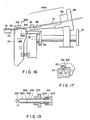
- A fourth embodiment of this invention is shown in Figs. l6 and l7. As shown in Fig. l6, rib l82 is formed on almost half of the top surface of
support block 24. Rib l82 provides a stepped portion. Groove l84 is formed in rib l82, as well illustrated in fig. l7. The groove allows optical fiber l0 to smoothly be set in place. The width of groove l84 is narrower than that ofsheath clamp 26. - The operation of this embodiment is as follows.
-
Dial 32 is turned andswash plate cam 34 is then turned. In turn,support block 24 is pushed byspindle 36 and turned in the direction of arrow l86. With this turning ofblock 24,sheath clamp 26 is placed on the rib l82 and clamp 26 is released from its clamping state. - In the third and fourth embodiments, the same or corresponding portions of those in Figs. 4 and 5 are not explained and illustrated, for simplicity. For the alignment of optical fibers in the circumferential direction, it is possible to use the automatic adjustment and/or manual adjustment. The combination of the automatic and manual adjustments is preferable from a standpoint of working efficiency.
- In the third and fourth embodiments, in the alignment in the circumferential direction, the sheath clamp is released from its clamping state. Therefore, the impedance for the turning of the fibers is little, realizing an exact alignment of optical fibers.
- In the circumferential direction alignment, a twisting force is applied to the portions of the optical fibers, which are outside the rotatable clamp 6l.
- After the fusion-splice of the optical fibers is completed, the spliced fiber is removed from the apparatus, and the spliced part of the fiber is reinforced. When the spliced fiber is removed,
fiber clamp 22,sheath clamp 26 and rotatable clamp 6l are all removed. At this time, twisting force is directly applied to the spliced part of the fiber. - A polarization maintaining optical fiber is sensitive to the twist. It is, therefore, preferable to apply the reinforcement to the spliced part of the optical fiber with less twist.
- A fifth embodiment of this invention will be described. In this embodiment, after the fusion-splicing of the optical fibers,
twist preventing unit 40 is attached to the fusion-splicing apparatus which clamps the spliced optical fiber to lock the fiber against its turn. This will be described referring to Figs. l8 and l9. - As shown in Fig. l8,
twist preventing unit 240 is comprised ofarm 242 and clamp means 256.Arm 242 is a bar shaped square in cross section. It can be divided into two sections, right and lefthalves bar 246 is projected from the end face of theleft half section 243. Thiscoupling bar 246 is slidably fitted into the end portion of theright half section 244.Pin 248 ofcoupling bar 246 andelongated hole 250 of theright half section 244 cooperate to limit the sliding range of these sections. Clamp means 256 are planted in both ends ofarm 242. Each of clamp means 256 contains circular rod likeshaft 258. This shaft is fixed at the base toarm 242, and has aU-shaped groove 260 at the top. Optical fiber is fit ingroove 260.Sleeve 262 is slidably fitted aroundshaft 258. The base ofsleeve 262 is slidably fitted in concave 24l ofarm 242. It is always biased to the left byspring 264 as shown in Fig. l9.Pin 266 is mounted toshaft 258.Pin 266 is coupled withelongated hole 268 ofsleeve 262 to prevent the sleeve from slipping off and to limit the movement ofsleeve 262.Knob 270 is fixed tosleeve 262. - In use,
sleeve 262 is moved towardarm 242 by a finger as shown in Fig. l9. Optical fiber l0 is inserted intogroove 60, and the finger is detached from it. Then,sleeve 262 is automatically returned to its original place byspring 264. In turn, optical fiber l0 is pushed against the side wall ofgroove 260 for clamping. Under this condition, the fiber is locked against its turn. - A couple of
circular rods 254 are upstanding on the upper surface of frame ll4 of the apparatus, while spaced by a predetermined distance. The rods are inserted into elongatedholes 252 ofarm 242 to removably attach the twist preventing unit to the frame ll4 of the apparatus. - The operation of this embodiment will be described.
- The operation of the fusion-splicing apparatus until the fusion-splice is substantially the same as those of the embodiments already mentioned, and hence the description thereof will be omitted.
- (l) Following the fusion-splice of the optical fibers, the twist preventing unit is attached to the fusion-splicing apparatus, by inserting
upstanding rods 254 intoelongated holes 252. Optical fiber l0 is clamped by means of clamp means 256. While in the embodiment of Figs. 4 and 5, therotating mechanism 44B is automatically driven by the motor, in this embodiment, it is manually driven by the dial. For this, it is designated as 44Bʹ. - (2) Then, rotatable clamp 6l is released. After the screening is completed,
fiber clamp 22 andsheath clamp 26 are released. - (3) Since the
rotating mechanisms 44A and 44Bʹ are slanted forwardly, optical fiber l0 is shaped like widely opened V. Therefore, if it is removed from the apparatus, it has a slack. To eliminate this slack, the right and lefthalf sections - According to this embodiment, prior to the reinforcement of the spliced part of the fiber, the fiber portion at the outside of the spliced part of the fiber is clamped by the twist preventing unit, and then the fiber is removed for the reinforcement. Therefore, the twist problems can be solved successfully.
- As seen from the foregoing, the present invention provides an apparatus for fusion-splicing a pair of polarization maintaining optical fibers, which can remarkably improve the alignment of optical fibers.
Claims (7)
rotating means (44A, 44B) including a first mechanical means (44A) for clamping one of a pair of polarization maintaining optical fibers (l0), and for rotating said clamped optical fiber about its axis, a second mechanical means (44B) for clamping the other polarization maintaining optical fiber, and for rotating said clamped optical fiber about its axis, whereby said pair of the optical fibers are aligned with each other; and
means (38) for fusion-splicing said pair of optical fibers by an arc discharge after said fibers are aligned with each other;
characterized in that
said first mechanical means (44A) manually rotates said clamped optical fiber and said second mechanical means (44B) rotates said clamped optical fiber by a motor (72), and
characterized by further comprising
rotation control means for controlling the rotation of said motor so as to vary the extinction ratio of light emitted from the light emitting end of said pair of optical fibers.
stopper means (39) to which the end faces of a pair of polarization maintaining optical fibers (l0) abut;
a microscope (90) for observing the alignment of said pair of optical fibers;
rotating means (44A, 44B) for clamping said pair of optical fibers, and rotating said pair of clamped optical fibers about their axes manually, whereby said pair of optical fibers are aligned with each other; and
means for fusion-splicing said pair of aligned optical fibers by an arc discharge,
characterized in that
said stopper means (39) is provided with mirror means (l04) for reflecting an image of the end faces of said pair of optical fibers when said mirror means is set at the place where said pair of optical fibers are made abut at the end faces; and
said microscope (90) picks up an image of the end faces of said optical fibers via said mirror means, and
characterized by further comprising
means (ll2, ll6, ll8) for setting said mirror means at the highest position higher than the end face abutting position, said end face abutting position, and the lowest position lower than said end face abutting position.
fiber clamps (22) and sheath clamps (26) for respectively clamping the exposed fiber portions (l2) and the covered fiber portions (ll) of a pair of polarization maintaining optical fibers (l0), said fiber clamps and sheath clamps being interlocked in operation;
rotating means (44A, 44B) for clamping said pair of optical fibers and rotating said clamped optical fibers about their axes, whereby said pair of optical fibers are aligned with each other; and
means for fusion-splicing said pair of aligned optical fibers by an arc discharge, and
characterized by further comprising
sheath clamp releasing means (l34, l36, l40, l44, l46) for releasing said sheath clamps from clamping of said covered fiber portions, while said exposed fiber portions are being clamped by said fiber clamps.
rotating means (44Aʹ, 44B) for clamping a pair of polarization maintaining optical fibers (l0) and rotating said clamped optical fibers about their axes, whereby said pair of optical fibers are aligned with each other; and
means (38) for fusion-splicing said pair of aligned optical fibers by an arc discharge, and
characterized by further comprising
twist preventing means including an arm (242) removably coupled with the fusion-splicing apparatus and clamp means (256) for clamping said pair of optical fibers when said arm is coupled with the fusion-splicing apparatus, said clamp means extending from each end of said arm, whereby, when said pair of optical fibers coupled with twist preventing means are removed from the fusion-splicing apparatus, no twist is generated to said pair of optical fibers.
Applications Claiming Priority (8)
| Application Number | Priority Date | Filing Date | Title |
|---|---|---|---|
| JP115903/86 | 1986-05-20 | ||
| JP115904/86 | 1986-05-20 | ||
| JP115901/86 | 1986-05-20 | ||
| JP115902/86 | 1986-05-20 | ||
| JP11590386A JPS62272210A (en) | 1986-05-20 | 1986-05-20 | Fusion splicing device for constant polarizing optical fiber |
| JP61115901A JPH073493B2 (en) | 1986-05-20 | 1986-05-20 | Method of fusion splicing of constant polarization optical fiber |
| JP11590286A JPS62272209A (en) | 1986-05-20 | 1986-05-20 | Fusion splicing device for constant polarizing optical fiber |
| JP11590486A JPS62272208A (en) | 1986-05-20 | 1986-05-20 | Fusion splicing device for constant polarization optical fiber |
Related Child Applications (1)
| Application Number | Title | Priority Date | Filing Date |
|---|---|---|---|
| EP91100516.3 Division-Into | 1987-05-20 |
Publications (3)
| Publication Number | Publication Date |
|---|---|
| EP0246636A2 true EP0246636A2 (en) | 1987-11-25 |
| EP0246636A3 EP0246636A3 (en) | 1989-04-19 |
| EP0246636B1 EP0246636B1 (en) | 1993-03-03 |
Family
ID=27470299
Family Applications (2)
| Application Number | Title | Priority Date | Filing Date |
|---|---|---|---|
| EP91100516A Withdrawn EP0427705A1 (en) | 1986-05-20 | 1987-05-20 | Apparatus for fusion-splicing a pair of polarization maintaining optical fibers |
| EP87107350A Expired - Lifetime EP0246636B1 (en) | 1986-05-20 | 1987-05-20 | Apparatus for fusion-splicing a pair of polarization maintaining optical fibers |
Family Applications Before (1)
| Application Number | Title | Priority Date | Filing Date |
|---|---|---|---|
| EP91100516A Withdrawn EP0427705A1 (en) | 1986-05-20 | 1987-05-20 | Apparatus for fusion-splicing a pair of polarization maintaining optical fibers |
Country Status (4)
| Country | Link |
|---|---|
| US (3) | US4986843A (en) |
| EP (2) | EP0427705A1 (en) |
| CA (1) | CA1302692C (en) |
| DE (1) | DE3784372T2 (en) |
Cited By (2)
| Publication number | Priority date | Publication date | Assignee | Title |
|---|---|---|---|---|
| EP0319041A3 (en) * | 1987-12-04 | 1990-05-16 | Fujikura Ltd. | Method and apparatus for fusion-splicing polarization maintaining optical fibers |
| US5766300A (en) * | 1995-07-11 | 1998-06-16 | Telefonaktiebolaget Lm Ericsson | Welding device for optical PM-fibers |
Families Citing this family (24)
| Publication number | Priority date | Publication date | Assignee | Title |
|---|---|---|---|---|
| FR2671409B1 (en) * | 1991-01-08 | 1994-06-10 | Alcatel Fibres Optiques | MICROSOLDER FOR OPTICAL FIBERS AND WELDING METHOD USING THE SAME. |
| US5283847A (en) * | 1991-09-09 | 1994-02-01 | Sumitomo Electric Industries, Ltd. | Method of manufacturing and evaluating an optical fiber coupler and apparatus therefor |
| FR2736441B1 (en) * | 1995-07-04 | 1997-09-26 | Noane Georges Le | DEVICE AND METHOD FOR TRACKING AND CONNECTING MULTI-CORE FIBERS |
| CA2232304A1 (en) * | 1995-09-29 | 1997-04-03 | William J. Simmons, Jr. | Method and apparatus for making fiber optic couplers |
| EP0886799A1 (en) * | 1996-03-14 | 1998-12-30 | Siemens Aktiengesellschaft | Splicing means for bonding two optical wave guides, one thereof being fixed in a connector pin |
| US6272886B1 (en) | 1996-10-23 | 2001-08-14 | 3M Innovative Properties Company | Incremental method of producing multiple UV-induced gratings on a single optical fiber |
| US5881185A (en) * | 1996-08-19 | 1999-03-09 | Honeywell Inc. | Method and apparatus for accurately fabricating a depolarizer |
| GB2330424B (en) * | 1997-11-21 | 1999-09-08 | Bookham Technology Ltd | Apparatus for connecting an optical fibre to an optical device |
| EP1130429A1 (en) * | 2000-03-02 | 2001-09-05 | Corning Incorporated | Method and apparatus for aligning and splicing of optical fibers |
| US6622376B1 (en) * | 2000-04-13 | 2003-09-23 | Capewell Components Company, Llc | Cylindrical fiber holder |
| SE522957C2 (en) * | 2000-09-11 | 2004-03-16 | Ericsson Telefon Ab L M | A device for providing polarized light |
| US6918269B2 (en) * | 2001-05-01 | 2005-07-19 | Phillip Hua-Kuan Wang | Optical fiber aligning method |
| GB2376307B (en) * | 2001-06-07 | 2003-05-14 | Melles Griot Ltd | Fibre rotation devices and methods |
| EP1494000A1 (en) * | 2003-07-02 | 2005-01-05 | Sicpa Holding S.A. | Method of marking a material with ions already comprised in said material and method of verifying the authenticity of said material |
| DE102006030545A1 (en) * | 2006-07-03 | 2008-01-10 | CCS Technology, Inc., Wilmington | Splicer, has threaded spindle driven by motor unit, spindle nut arranged on threaded spindle in movable manner, and retaining device provided for mechanical coupling of fiber holder with spindle nut |
| CN101923188B (en) * | 2010-06-22 | 2012-06-27 | 上海亨通光电科技有限公司 | Stress axis fixation method of polarization-maintaining fiber |
| US9057838B2 (en) | 2011-06-27 | 2015-06-16 | Vytran, Llc | Apparatus and methods for the determination of a birefringence axis of a polarization-maintaining optical fiber |
| US20140102148A1 (en) * | 2012-10-11 | 2014-04-17 | Fujitsu Limited | System and Method for Splicing Optical Fibers in Order to Mitigate Polarization Dependent Splice Loss |
| USD720785S1 (en) * | 2013-10-30 | 2015-01-06 | Sei Optifrontier Co., Ltd. | Electrode bar for optical fiber fusion splicer |
| CN106908902A (en) * | 2017-04-14 | 2017-06-30 | 上海康阔光传感技术股份有限公司 | Optical fiber splicer and optical fiber splicing method |
| DE102018114741B4 (en) * | 2018-06-19 | 2022-06-30 | AIXEMTEC GmbH | Apparatus and method for aligning polarization-maintaining optical fibers |
| US12169305B2 (en) * | 2019-02-05 | 2024-12-17 | Sumitomo Electric Optifrontier Co., Ltd. | Fusion splicing device and fusion splicing method |
| DE102020114610A1 (en) | 2020-06-02 | 2021-12-02 | Heidelberg Engineering Gmbh | Arrangement for performing an optical coherence tomography |
| US20220350080A1 (en) * | 2021-04-29 | 2022-11-03 | Ram Photonics Llc | Method and system for aligning and splicing polarization maintaining fibers |
Family Cites Families (27)
| Publication number | Priority date | Publication date | Assignee | Title |
|---|---|---|---|---|
| US4049414A (en) * | 1975-07-28 | 1977-09-20 | Corning Glass Works | Method and apparatus for splicing optical fibers |
| JPS5329143A (en) * | 1976-08-31 | 1978-03-18 | Oki Electric Ind Co Ltd | Optical fiber connector |
| US4248499A (en) * | 1978-02-23 | 1981-02-03 | Siemens Aktiengesellschaft | Splicing device for light wave guides |
| US4245885A (en) * | 1978-10-30 | 1981-01-20 | Trw Inc. | Fiber optic relay switch for precise fiber alignment and method of making the same |
| US4315666A (en) * | 1979-03-19 | 1982-02-16 | Hicks Jr John W | Coupled communications fibers |
| US4372768A (en) * | 1981-04-27 | 1983-02-08 | Gte Automatic Electric Laboratories, Inc. | Method of splicing ends of optical fibers |
| US4375768A (en) * | 1981-06-17 | 1983-03-08 | Auergesellschaft Gmbh | Electronic circuit for processing the measured values from a vortex sequence produced by a Karman vortex path |
| JPS5810722A (en) * | 1981-07-10 | 1983-01-21 | Matsushita Electric Ind Co Ltd | Method of manufacturing electrochromic display device |
| GB2117916B (en) * | 1982-02-17 | 1986-08-28 | Standard Telephones Cables Ltd | Optic fibre fusion splicing |
| CA1167299A (en) * | 1982-04-14 | 1984-05-15 | Koichi Abe | Precise positioning of optical fibers |
| US4516021A (en) * | 1982-08-09 | 1985-05-07 | Taylor Henry F | Fiber optic magnetic field sensor |
| US4603941A (en) * | 1982-09-27 | 1986-08-05 | Agency Of Industrial Science And Technology | Polarization-maintaining fiber system and method of manufacturing the same |
| JPS5960411A (en) * | 1982-09-30 | 1984-04-06 | Nippon Telegr & Teleph Corp <Ntt> | Connecting method of optical fiber |
| JPS59174808A (en) * | 1983-03-25 | 1984-10-03 | Nippon Telegr & Teleph Corp <Ntt> | Optical fiber connecting method |
| DE3325157A1 (en) * | 1983-07-12 | 1985-01-31 | Siemens AG, 1000 Berlin und 8000 München | Welding device for optical fibre cables |
| DE3329293A1 (en) * | 1983-08-12 | 1985-02-28 | Siemens AG, 1000 Berlin und 8000 München | DEVICE FOR ALIGNING A FOCUS FOR SPLICE PURPOSES |
| EP0142062B1 (en) * | 1983-10-24 | 1988-06-01 | COMPAGNIE LYONNAISE DE TRANSMISSIONS OPTIQUES Société anonyme dite: | Automatic machine for fusion splicing the ends of optical fibres |
| US4557557A (en) * | 1983-10-28 | 1985-12-10 | At&T Bell Laboratories | Method of making an optical fiber attenuator using a lossy fusion splice |
| GB2150703B (en) * | 1983-11-30 | 1987-03-11 | Standard Telephones Cables Ltd | Single mode fibre directional coupler |
| JPS60232513A (en) * | 1984-05-01 | 1985-11-19 | Nippon Telegr & Teleph Corp <Ntt> | Method for connecting optical fiber by welding |
| JPH0614129B2 (en) * | 1984-12-17 | 1994-02-23 | 株式会社フジクラ | Fusion method of fused silica single mode optical fiber |
| JPS6261010A (en) * | 1985-09-12 | 1987-03-17 | Kokusai Denshin Denwa Co Ltd <Kdd> | Fusion splicing method for optical fibers |
| DE3613345A1 (en) * | 1986-04-19 | 1987-10-22 | Philips Patentverwaltung | DEVICE FOR PAIRING THE ENDS OF TWO GROUPS OF FIBER-SHAPED FIBER-WAVE GUIDES IN PAIRS |
| GB8611361D0 (en) * | 1986-05-09 | 1986-06-18 | Bicc Plc | Splicing optical fibre ribbon |
| JPS63184712A (en) * | 1986-09-26 | 1988-07-30 | Sumitomo Electric Ind Ltd | Optical fiber connection method |
| US4759252A (en) * | 1987-05-01 | 1988-07-26 | Lyons Music, Inc. | Mute holder |
| US5013345A (en) * | 1987-12-04 | 1991-05-07 | Fujikura Ltd. | Method of fusion-splicing polarization maintaining optical fibers |
-
1987
- 1987-05-20 DE DE8787107350T patent/DE3784372T2/en not_active Expired - Lifetime
- 1987-05-20 EP EP91100516A patent/EP0427705A1/en not_active Withdrawn
- 1987-05-20 EP EP87107350A patent/EP0246636B1/en not_active Expired - Lifetime
- 1987-05-20 CA CA000537461A patent/CA1302692C/en not_active Expired - Lifetime
-
1989
- 1989-07-11 US US07/379,690 patent/US4986843A/en not_active Expired - Lifetime
-
1991
- 1991-04-16 US US07/686,750 patent/US5147434A/en not_active Expired - Lifetime
- 1991-04-16 US US07/686,747 patent/US5156663A/en not_active Expired - Lifetime
Cited By (4)
| Publication number | Priority date | Publication date | Assignee | Title |
|---|---|---|---|---|
| EP0319041A3 (en) * | 1987-12-04 | 1990-05-16 | Fujikura Ltd. | Method and apparatus for fusion-splicing polarization maintaining optical fibers |
| US5013345A (en) * | 1987-12-04 | 1991-05-07 | Fujikura Ltd. | Method of fusion-splicing polarization maintaining optical fibers |
| US5766300A (en) * | 1995-07-11 | 1998-06-16 | Telefonaktiebolaget Lm Ericsson | Welding device for optical PM-fibers |
| US6151919A (en) * | 1995-07-11 | 2000-11-28 | Telefonaktiebolaget Lm Ericsson | Welding device for optical PM-fibers |
Also Published As
| Publication number | Publication date |
|---|---|
| EP0427705A1 (en) | 1991-05-15 |
| US5147434A (en) | 1992-09-15 |
| DE3784372D1 (en) | 1993-04-15 |
| DE3784372T2 (en) | 1993-08-12 |
| EP0246636B1 (en) | 1993-03-03 |
| EP0246636A3 (en) | 1989-04-19 |
| US4986843A (en) | 1991-01-22 |
| CA1302692C (en) | 1992-06-09 |
| US5156663A (en) | 1992-10-20 |
Similar Documents
| Publication | Publication Date | Title |
|---|---|---|
| EP0246636A2 (en) | Apparatus for fusion-splicing a pair of polarization maintaining optical fibers | |
| US5149350A (en) | Apparatus for fusion-splicing a pair of polarization maintaining optical fibers | |
| EP0319041B1 (en) | Method and apparatus for fusion-splicing polarization maintaining optical fibers | |
| US7255498B2 (en) | Low profile system for joining optical fiber waveguides | |
| US6984077B2 (en) | System for joining polarization-maintaining optical fiber waveguides | |
| AU710445B2 (en) | Method and apparatus for observing tip portion of optical fibers butting each other | |
| US4474469A (en) | Precise positioning of optical fibers | |
| EP0295825A1 (en) | Method of achieving improved radial alignment in an optical package | |
| EP0233709B1 (en) | Fusion apparatus for joining two monomode optical fibers | |
| JP3345856B2 (en) | Screening mechanism of optical fiber fusion splicer | |
| CN117642663A (en) | Welding machine | |
| EP0091738B1 (en) | Precise positioning of optical fibers | |
| JPH073493B2 (en) | Method of fusion splicing of constant polarization optical fiber | |
| EP0788611A1 (en) | Splicing an optical fiber having twin cores and a fiber having a single core | |
| CN209690560U (en) | Fiber end face optical imagery structure and optical fiber splicer | |
| JPS5995506A (en) | Optical fiber connecting method | |
| CN1250991C (en) | Optical fibre axial alignment method and relative equipment, optical fibre welding method and relative equipment | |
| JP3171552B2 (en) | Optical fiber connection device | |
| KR20260018803A (en) | Optical fiber positioning device and method | |
| JPH0575083B2 (en) | ||
| JP3607642B2 (en) | Optical fiber fusion splicer | |
| JP4076374B2 (en) | Scanning probe device | |
| KR102064838B1 (en) | Fusion splicer for optical fiber | |
| JP3007827B2 (en) | Optical fiber array assembly method | |
| JPH0954221A (en) | Optical fiber core alignment method and alignment device |
Legal Events
| Date | Code | Title | Description |
|---|---|---|---|
| PUAI | Public reference made under article 153(3) epc to a published international application that has entered the european phase |
Free format text: ORIGINAL CODE: 0009012 |
|
| 17P | Request for examination filed |
Effective date: 19870520 |
|
| AK | Designated contracting states |
Kind code of ref document: A2 Designated state(s): DE FR GB |
|
| PUAL | Search report despatched |
Free format text: ORIGINAL CODE: 0009013 |
|
| AK | Designated contracting states |
Kind code of ref document: A3 Designated state(s): DE FR GB |
|
| RAP1 | Party data changed (applicant data changed or rights of an application transferred) |
Owner name: NIPPON TELEGRAPH AND TELEPHONE CORPORATION Owner name: FUJIKURA LTD. |
|
| RIN1 | Information on inventor provided before grant (corrected) |
Inventor name: KATO, YASUYUKI 1-102,NIPPON DENSHINDENWA Inventor name: YOSHINUMA, MIKIO Inventor name: ONODERA, TSUTOMU Inventor name: YAMADA, TAKESHI Inventor name: ITOH, KENICHIRO |
|
| 17Q | First examination report despatched |
Effective date: 19900720 |
|
| GRAA | (expected) grant |
Free format text: ORIGINAL CODE: 0009210 |
|
| AK | Designated contracting states |
Kind code of ref document: B1 Designated state(s): DE FR GB |
|
| REF | Corresponds to: |
Ref document number: 3784372 Country of ref document: DE Date of ref document: 19930415 |
|
| ET | Fr: translation filed | ||
| PLBE | No opposition filed within time limit |
Free format text: ORIGINAL CODE: 0009261 |
|
| STAA | Information on the status of an ep patent application or granted ep patent |
Free format text: STATUS: NO OPPOSITION FILED WITHIN TIME LIMIT |
|
| 26N | No opposition filed | ||
| REG | Reference to a national code |
Ref country code: GB Ref legal event code: IF02 |
|
| PGFP | Annual fee paid to national office [announced via postgrant information from national office to epo] |
Ref country code: FR Payment date: 20060411 Year of fee payment: 20 |
|
| PGFP | Annual fee paid to national office [announced via postgrant information from national office to epo] |
Ref country code: GB Payment date: 20060517 Year of fee payment: 20 |
|
| PGFP | Annual fee paid to national office [announced via postgrant information from national office to epo] |
Ref country code: DE Payment date: 20060522 Year of fee payment: 20 |
|
| REG | Reference to a national code |
Ref country code: GB Ref legal event code: PE20 |
|
| PG25 | Lapsed in a contracting state [announced via postgrant information from national office to epo] |
Ref country code: GB Free format text: LAPSE BECAUSE OF EXPIRATION OF PROTECTION Effective date: 20070519 |