EP0246597A2 - Method of reproducing signals from optical disk - Google Patents
Method of reproducing signals from optical disk Download PDFInfo
- Publication number
- EP0246597A2 EP0246597A2 EP87107210A EP87107210A EP0246597A2 EP 0246597 A2 EP0246597 A2 EP 0246597A2 EP 87107210 A EP87107210 A EP 87107210A EP 87107210 A EP87107210 A EP 87107210A EP 0246597 A2 EP0246597 A2 EP 0246597A2
- Authority
- EP
- European Patent Office
- Prior art keywords
- photodetector
- track groove
- output
- signal
- amplifying
- Prior art date
- Legal status (The legal status is an assumption and is not a legal conclusion. Google has not performed a legal analysis and makes no representation as to the accuracy of the status listed.)
- Granted
Links
- 230000003287 optical effect Effects 0.000 title claims abstract description 32
- 238000000034 method Methods 0.000 title claims abstract description 29
- 230000003321 amplification Effects 0.000 claims description 14
- 238000003199 nucleic acid amplification method Methods 0.000 claims description 14
- 230000007935 neutral effect Effects 0.000 claims 1
- 230000033458 reproduction Effects 0.000 description 15
- 238000009434 installation Methods 0.000 description 5
- 230000002093 peripheral effect Effects 0.000 description 5
- 239000011295 pitch Substances 0.000 description 4
- RYGMFSIKBFXOCR-UHFFFAOYSA-N Copper Chemical compound [Cu] RYGMFSIKBFXOCR-UHFFFAOYSA-N 0.000 description 3
- 229910052802 copper Inorganic materials 0.000 description 3
- 239000010949 copper Substances 0.000 description 3
- 238000002474 experimental method Methods 0.000 description 3
- 239000004065 semiconductor Substances 0.000 description 3
- 230000008878 coupling Effects 0.000 description 2
- 238000010168 coupling process Methods 0.000 description 2
- 238000005859 coupling reaction Methods 0.000 description 2
- 238000001514 detection method Methods 0.000 description 2
- 229910003460 diamond Inorganic materials 0.000 description 2
- 239000010432 diamond Substances 0.000 description 2
- 238000001228 spectrum Methods 0.000 description 2
- 241001422033 Thestylus Species 0.000 description 1
- 230000003292 diminished effect Effects 0.000 description 1
- 230000000694 effects Effects 0.000 description 1
- 238000003672 processing method Methods 0.000 description 1
Images


Classifications
-
- G—PHYSICS
- G11—INFORMATION STORAGE
- G11B—INFORMATION STORAGE BASED ON RELATIVE MOVEMENT BETWEEN RECORD CARRIER AND TRANSDUCER
- G11B7/00—Recording or reproducing by optical means, e.g. recording using a thermal beam of optical radiation by modifying optical properties or the physical structure, reproducing using an optical beam at lower power by sensing optical properties; Record carriers therefor
- G11B7/08—Disposition or mounting of heads or light sources relatively to record carriers
- G11B7/09—Disposition or mounting of heads or light sources relatively to record carriers with provision for moving the light beam or focus plane for the purpose of maintaining alignment of the light beam relative to the record carrier during transducing operation, e.g. to compensate for surface irregularities of the latter or for track following
-
- G—PHYSICS
- G11—INFORMATION STORAGE
- G11B—INFORMATION STORAGE BASED ON RELATIVE MOVEMENT BETWEEN RECORD CARRIER AND TRANSDUCER
- G11B7/00—Recording or reproducing by optical means, e.g. recording using a thermal beam of optical radiation by modifying optical properties or the physical structure, reproducing using an optical beam at lower power by sensing optical properties; Record carriers therefor
- G11B7/004—Recording, reproducing or erasing methods; Read, write or erase circuits therefor
- G11B7/005—Reproducing
-
- G—PHYSICS
- G11—INFORMATION STORAGE
- G11B—INFORMATION STORAGE BASED ON RELATIVE MOVEMENT BETWEEN RECORD CARRIER AND TRANSDUCER
- G11B7/00—Recording or reproducing by optical means, e.g. recording using a thermal beam of optical radiation by modifying optical properties or the physical structure, reproducing using an optical beam at lower power by sensing optical properties; Record carriers therefor
- G11B7/24—Record carriers characterised by shape, structure or physical properties, or by the selection of the material
- G11B7/2407—Tracks or pits; Shape, structure or physical properties thereof
- G11B7/24073—Tracks
- G11B7/24076—Cross sectional shape in the radial direction of a disc, e.g. asymmetrical cross sectional shape
Definitions
- the present invention relates to a method of reproducing or reading, by means of a laser beam, signals which have been recorded in an optical disk.
- a method has been proposed in the specification of United States Patent No. 4,569,038 for recording data at a high density in an optical disk, by making use of V-shaped track grooves. More specifically, in this proposed method, a V-shaped track groove having slant side surfaces is formed in an optical disk at a pitch which is substantially the same as the pitches of recording tracks in conventional optical disks. In this method, signals are recorded in both slant side surfaces so that the recording density is substantially doubled. In the reproduction of the recorded signals, the beam portion reflected by the optical disk is received by a photodetector. However, the reproducing device does not reproduce whole the reflected beam but only the peripheral portion of the reflected beam.
- the reproduction region in the beam By suitably selecting the reproduction region in the beam, it is possible to reduce any crosstalk from the adjacent slant side surface of the V-shaped track groove. This is one of advantageous features offered by the V-shaped track groove.
- the reflected beam involves not only a reproduction with small crosstalk component but also a region which has a large crosstalk component though the light quantity is small. Therefore, the reproduction of signal is preferably conducted by means of a photodetector which is capable of reproducing signals only in the region having small crosstalk component. In order to obtain a sufficiently low level of crosstalk, e.g., -36 dB, it is necessary to ensure high degree of accuracy not only in design but also in installation of the photodetector.
- the photodetector for receiving the beam reflected by the optical disk is composed of a first photodetector and a second photodetector. More specifically, the first photodetector is designed for receiving the reflected beam portion having the small crosstalk component, while the second photodetector is adapted for receiving the reflected beam portion having the large crosstalk component.
- the signal derived from the first photodetector is multiplied with an amplification M1, while the signal derived from the second photodetector is multiplied with an amplification M2.
- the output of the second photodetector after multiplication by M2 is subtracted from the output of the first photodetector after multiplication by M1 and the difference is used as the reproduction signal.
- the magnification factor M1 is greater than the amplification factor M2.
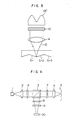
- the V-shaped track groove is formed by mechanically cutting a copper disk by means of a diamond stylus having a V-shaped point while rotating the copper disk.
- the V-shaped point of the diamond stylus has an apex angle of l62° and the stylus is moved radially inwardly by about l.65 ⁇ m per each rotation of the copper disk.
- a mother disk is formed in which a V-shaped spiral track groove, defined by opposing slant surfaces which make an angle of l62° therebetween, is formed at a pitch of l.65 ⁇ m. It is possible to form a stamper and a replica by making use of this mother disk. This method is disclosed also in the specification of United States Patent No. 569,038.
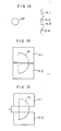
- the optical system includes a semiconductor laser l, a coupling lens 2, a beam splitter 3, an objective lens 4, the V-shaped track groove 5, and a reproducing photodetector l0. Incidence light beam and reflected light beam are designated by numerals ll and l2, respectively.
- Fig. l lacks any illustration of controlling optical system.
- the specification of United States Patent No. 4,569,038 also disclosed a method of reproducing signals from the slant surfaces of the V-shaped track groove.
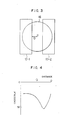
- Fig. 2 illustrates only the beam reflected from a slant surface of a V-shaped track groove.
- slant surfaces of V-shaped track grooves are denoted by numerals 5-l, 5-2, 5-3 and 5-4.
- a curve l3 shows the distribution of intensity of the reflected beam as received by the photodetector. Not whole of this reflected beam but only a peripheral region, e.g., hatched region l4, is reproduced. As explained before, it is one of the critical features of the V-shaped track groove that the crosstalk from the adjacent slant surface is diminished by suitable selection of the region to be reproduced.
- the region opposite to the peripheral region l4, e.g., the hatched area l5, is the region which has a large crosstalk component.
- each reflected beam includes separate portions: namely, a portion having a small crosstalk component and a portion having a large crosstalk component but of a small light quality.
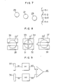
- the reproduction of the signal from the reflected beam therefore essentially necessitates a photodetector of split type composed of two photodetector units l0-l and l0-2 as shown in Fig. 3. More specifically, the photodetector used for the reproduction has first and second photodetector units and which are arranged in symmetry with each other with respect to a line which passes through the center of the reflected light beam and parallel to the track.
- the first photodetector unit receives a beam portion which has a small crosstalk component
- the second photodetector unit receives a beam which has large crosstalk component though the light quantity thereof is small.
- the photodetector unit l0-l is used as the first photodetector unit, while the photodetector unit l0-2 is used as the second photodetector unit, whereas, when the signals from the slant surfaces 5-2, 5-4 and so forth are reproduced, the photodetector units l0-2 and l0-l are used, respectively, as the first and the second photodetector units.
- a reference numeral l6 designates a circle having the same diameter as the reflected beam.
- Fig. 4 shows the amount of crosstalk along the distance Q (see Figs. 2 and 3) between the center axis of the reflected beam and the reproduction boundary. It is assumed here that the incidence light to the objective lens 4 has a Gaussian distribution pattern and that a portion of the reflected beam having the central intensity above l/e is converged through the objective lens. In the case of a variable-density recording in which the signals are recorded in the form of variations in reflection factors the distance Q at which the crosstalk is reduced is about l/4 of the diameter of the reflected beam.
- the variable-density recording is made possible by forming a TeOx recording film on the V-shaped track groove. For the detail of the TeOx recording film, a reference be made to M.
- the distance Q at which the crosstalk is sufficiently reduced is about l/l0 of the diameter of the reflected beam.
- the value of the distance Q will be increased when the intensity of the incident beam coming into the objective lens 4 has a uniform intensity distribution.
- the arrangement may be such that the laser beam spot tracks the bottom of the V-shaped track groove.
- Fig. 5 shows the beam reflected from the bottom of the V-shaped track groove. In this case, the reflected beam is distributed along a curve l3 ⁇ .
- the signals from the slant surface 5-l is received mainly by the photodetector unit l0-2
- the signals from the slant surface 5-2 is received mainly by the photodetector unit l0-l.
- Both the signals received by the photodetector units l0-l and l0-2 have large crosstalk components. In this case, it is impossible to reduce the crosstalk even though the accuracy of the photodetector shown in Fig. 3 is increased.
- the beam reflected from the slant surface of the V-shaped track groove has two separate portions: namely, a portion having a small crosstalk component and a portion having a large crosstalk component.
- the present invention proposes a method which can reduce the strictness for the requirement for accuracy of the design and installation of the photodetector.
- Such a method also enables signals from two slant surfaces of the same V-shaped track groove by means of a single laser beam.
- the beam reflected by a V-shaped track groove is reproduced by means of a photodetector of split type having first and second photodetector units.
- the first photodetector unit produces a detection signal having a small crosstalk component
- the second photodetector unit produces a detection signal having a large crosstalk component.
- a signal obtained by amplifying the output of the second photodetector unit is subtracted from a signal obtained by amplifying the output of the first photodetector unit, thus determining the difference which is used as the reproduction signal.
- the crosstalk component involved by the signal output from the first photodetector unit is negated by the crosstalk component of the output from the second photodetector unit, so that a signal of reduced crosstalk component is obtained while reducing the strictness of the requirement for design and installation of the photodetector.
- Fig. 6 shows an optical system which is incorporated in the first embodiment of the present invention.
- the optical system includes a diffraction grating 6, a quarter-wave plate 7, a lens system 8,9 for effecting astigmatic focus control, and a photo detector 30.
- Other components which are the same as those used in the optical system shown in Fig. l are denoted by the same reference numerals as those in Fig. l.
- the pitch of the V-shaped track groove i.e., the spacing between the adjacent crests, is l.65 ⁇ m, whereas the angle formed between two slant surfaces is l62°.
- the wavelength of the laser beam used is 780 nm, while the NA of the objective lens is 0.6.
- the photodetector 30 is composed of eight sections. The beams reflected from the spots 2l, 22 and 23 are received by the photodetector as at 2l ⁇ , 22 ⁇ and 23 ⁇ , respectively.
- the spot 2l is restricted by the crest or valley of the V-shaped track groove, and the focus control and tracking control by the respective photodetector units 3l to 34 are effected by making use of the reflected beam 2l ⁇ . More specifically, the focus control is effected in accordance with a signal which is obtained by subtracting the sum of output of the photodetector units 32 and 33 from the sum of the outputs from the photodetector units 3l and 34, while the tracking control is effected in accordance with a signal which is obtained by subtracting the sum of the outputs of the photodetector units 33 and 34 from the sum of the outputs of the photodetector units 3l and 32.
- the spots 22 and 23 are aimed on the centers of the adjacent slant surfaces of the V-shaped track groove, and the beams reflected therefrom include the signals to be reproduced.
- the signals are to be reproduced from the slant surface 5-2.
- the signal Sl from the photodetector 35 has a small crosstalk
- the signal S2 from the photodetector unit 36 has a large crosstalk component although the light quantity of this signal S2 is small.
- the reproduction system includes the following additional function. Namely, means are provided as shown in Fig. 9 for subtracting a signal S4 obtained by amplifying the signal S2 by an amplification factor M2 from a signal S3 obtained by amplifying the signal Sl by a multiplication factor M1.
- amplification factors M1 and M2 it is possible to obtain a signal S5 having a very small crosstalk component.
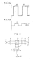
- Examples of such signal S3, S4 and S5 are shown in Figs. l0a and l0b.
- the crosstalk component C of the signal S3 may be increased to an unacceptable level if the designs of the photodetector units and the positions of the photodetector units are not set accurately.
- the crosstalk component C ⁇ of the signal S4 is subtracted from the crosstalk component C of the signal S3, so that the resultant signal S5 has a very small crosstalk component. It is thus possible to obtain the signal S5 which has so small crosstalk component that it can be satisfactorily used as the reproduced signal, even though the signal S3 itself has a large crosstalk component.
- the requirement of strictness for the design of the photodetector, e.g., the distance d shown in Fig. 3, and the positions of the photodetector units can be reduced advantageously.
- the crosstalk component of the signal S5 can be reduced to a satisfactorily low level by setting the amplification factors M1 and M2 to be l00 and 30, respectively. It will be clear to those skilled in the art that the same advantage can be obtained also when the signals are reproduced from the slant surface 5-3, by subtracting a signal obtained by amplifying the output of the photodetector unit 38 from a signal obtained by amplifying the output of the photodetector unit 37.
- Fig. ll shows an optical system which is incorporated in a second embodiment of the present invention.
- This optical system is designed for independently and simultaneously reproducing signals from both slant surfaces of a common V-shaped track groove, by applying the laser beam spot to the valley or bottom of the V-shaped track groove.
- the same reference numerals are used to denote the same parts or members as those used in the optical systems shown in Figs. l and 6.
- the shape of the V-shaped track groove, NA of the objective lens and the wavelength of the laser beam are the same as those used in the first embodiment.
- a lens l7 and a mirror l8 are used in combination so as to effect a focus control by a method generally referred to as "knife edge method", by making use of a split-type photodetector 40.
- the tracking control is conducted by a method generally referred to as “far-sight image push-pull method”, by making use of a photodetector 4l. Both these methods are well known and, hence, are not detailed in this specification.
- the tracking control is conducted to allow the laser beam spot to follow the bottom of the V-shaped track groove as shown in Fig. l2.
- Fig. l3 shows the detail of the photodetector 4l together with the reflected beam l9.
- the photodetector 4l is split into two units: namely, a unit 4l-l and 4l-2.
- the beam received by each photodetector unit is mainly constituted by signals derived from each slant surface.
- the beam also carries a large crosstalk component so that it cannot be used as the reproduced signal.
- the crosstalk component is on the order of -l0 to -l5 dB.
- the second embodiment of the invention therefore, proposes a signal processing method which will be explained hereinunder with reference to Fig. l4. Signals output from the photodetector units 4l-l and 4l-2 are denoted by Sll and Sl2, respectively.
- the signals Sll and Sl2 are amplified by amplification factor M4 so as to become signals Sl3 and Sl4.
- the amplification factor M4 is about l0 or so.
- the signals Sl3 and Sl4 are further amplified by an amplification factor M3 ⁇ so as to become signals Sl5 and Sl6.
- the product of the factors M4 and M3 ⁇ is represented by M3.
- signals Sl7 and Sl8 are obtained in accordance with the following formulae, and are used as the reproduced signals.
- Sl7 Sl5 - Sl4
- Sl8 Sl6 - Sl3
- each reproduction signal is obtained by subtracting, from a signal obtained by amplifying one of the outputs of the photodetector units 4l-l and 4l-2 by an amplification factor M3, a signal obtained by multiplying the output from the other photodetector units by a multiplication factor M4.
- Figs. l5a and l5b show the spectrums of the signals Sl5 and Sl6 obtained in an experiment which was conducted by making use of the photodetector of the type shown in Fig. l3.
- Crosstalk components represented by x and y are on the order of l0 to l5 dB. Therefore, the crosstalk components in the reproduced signals Sl7 and Sl8 can be reduced sufficiently if these signals are formed by using the amplification factor M3 ⁇ ranging between 3 and 4. It is true that the signal component to be reproduced also is reduced as a result of the subtracting operation. However, the amount of reduction of the signal component is about l dB or so which is negligibly small.
- the signals with small crosstalk component are concentrated to the peripheral region of the reflected beam.
- the photodetector shown in Fig. l6 is designed and situated to receive mainly the peripheral region of the beam.
- the crosstalk components x and y see Figs.
- the crosstalk components of the reproduced signals Sl7 and Sl8 can be reduced satisfactorily if the amplification factor M3 ⁇ is selected to be about l0. According to the second embodiment, therefore, it is possible to independently and simultaneously reproduce signals from both slant surfaces of a V-shaped track groove by means of a single laser beam spot.
- the present invention offers the following advantages.
- the photodetector for receiving the reflected beam is split into two parts: namely, first and second photodetector units.
- the reproduced signal is obtained by subtracting, from a signal obtained by amplifying the output of the first photodetector unit, a signal obtained by amplifying the output of the second photodetector unit, so that the crosstalk component in the reproduced signal is reduced remarkably. This in turn reduces the strictness of requirement for accuracy in the design and installation of the photodetector.
- the method of the invention makes it possible to independently and simultaneously reproduce signals from both slant surfaces of a V-shaped track groove by means of a single laser beam spot.
Landscapes
- Optical Recording Or Reproduction (AREA)
- Optical Head (AREA)
Abstract
Description
- The present invention relates to a method of reproducing or reading, by means of a laser beam, signals which have been recorded in an optical disk.
- A method has been proposed in the specification of United States Patent No. 4,569,038 for recording data at a high density in an optical disk, by making use of V-shaped track grooves. More specifically, in this proposed method, a V-shaped track groove having slant side surfaces is formed in an optical disk at a pitch which is substantially the same as the pitches of recording tracks in conventional optical disks. In this method, signals are recorded in both slant side surfaces so that the recording density is substantially doubled. In the reproduction of the recorded signals, the beam portion reflected by the optical disk is received by a photodetector. However, the reproducing device does not reproduce whole the reflected beam but only the peripheral portion of the reflected beam. By suitably selecting the reproduction region in the beam, it is possible to reduce any crosstalk from the adjacent slant side surface of the V-shaped track groove. This is one of advantageous features offered by the V-shaped track groove. The reflected beam involves not only a reproduction with small crosstalk component but also a region which has a large crosstalk component though the light quantity is small. Therefore, the reproduction of signal is preferably conducted by means of a photodetector which is capable of reproducing signals only in the region having small crosstalk component. In order to obtain a sufficiently low level of crosstalk, e.g., -36 dB, it is necessary to ensure high degree of accuracy not only in design but also in installation of the photodetector.
- As stated before, light beam reflected from each slant side surface of the V-shaped track groove has a portion having a small crosstalk component and a portion having a large crosstalk component, these portions existing separately from each other. According to the invention, the photodetector for receiving the beam reflected by the optical disk is composed of a first photodetector and a second photodetector. More specifically, the first photodetector is designed for receiving the reflected beam portion having the small crosstalk component, while the second photodetector is adapted for receiving the reflected beam portion having the large crosstalk component. The signal derived from the first photodetector is multiplied with an amplification M₁, while the signal derived from the second photodetector is multiplied with an amplification M₂. The output of the second photodetector after multiplication by M₂ is subtracted from the output of the first photodetector after multiplication by M₁ and the difference is used as the reproduction signal. Usually, the magnification factor M₁ is greater than the amplification factor M₂. By subtracting the crosstalk component from the amplified output of the second photodetector from the crosstalk component of the magnified output of the first photodetector, it is possible to obtain a reproduction signal with reduced crosstalk component while reducing the strictness of the requirement for higher accuracy of design and installation of the photodetector. It is to be noted also that the method of the present invention enables independent reproduction of signals from both slant side surfaces of a V-shaped groove simultaneously by means of a single laser beam.
-
- Fig. l is an illustration of basic elements of an optical system including an optical disk;
- Fig. 2 is an illustration of a beam reflected from a V-shaped track groove and the region in the reflected beam to be reproduced;
- Fig. 3 is an illustration of a photodetector for reproducing signals recorded in a V-shaped track groove;
- Fig. 4 is an illustration of the relationship between the reproduced region and crosstalk component;
- Fig. 5 is an illustration of a beam reflected by the bottom of a V-shaped track groove;
- Fig. 6 is an illustration of an optical system incorporated in a first embodiment of the present invention;
- Fig. 7 is an illustration of a laser beam spot on an optical disk used in the embodiment shown in Fig. 6;
- Fig. 8 is an illustration of a photodetector incorporated in the first embodiment of the invention;
- Fig. 9 is an illustration of the way in which signals are formed in the first embodiment of the invention;
- Figs. l0a and l0b are illustrations of reproduction signals employed in the first embodiment of the invention;
- Fig. ll is an illustration of an optical system employed in a second embodiment of the present invention;
- Fig. l2 is an illustration of a laser beam spot on an optical disk used in the second embodiment of the invention;
- Fig. l3 is an illustration of a photodetector incorporated in the second embodiment of the invention;
- Fig. l4 is a schematic illustration showing the manner in which signals are processed in the second embodiment of the present invention;
- Figs. l5a and l5b are illustrations of spectrums in the second embodiment of the present invention; and
- Fig. l6 is an illustration of another example of a photodetector incorporated in the second embodiment of the present invention.
- A description will be made first as to the method of forming a V-shaped track groove in an optical disk. The V-shaped track groove is formed by mechanically cutting a copper disk by means of a diamond stylus having a V-shaped point while rotating the copper disk. For instance, the V-shaped point of the diamond stylus has an apex angle of l62° and the stylus is moved radially inwardly by about l.65 µm per each rotation of the copper disk. In consequence, a mother disk is formed in which a V-shaped spiral track groove, defined by opposing slant surfaces which make an angle of l62° therebetween, is formed at a pitch of l.65 µm. It is possible to form a stamper and a replica by making use of this mother disk. This method is disclosed also in the specification of United States Patent No. 569,038.
- Major components of the optical system for reproducing signals from the V-shaped track groove are shown in Fig. l. The optical system includes a semiconductor laser l, a
coupling lens 2, abeam splitter 3, anobjective lens 4, the V-shaped track groove 5, and a reproducing photodetector l0. Incidence light beam and reflected light beam are designated by numerals ll and l2, respectively. - The laser beam from the semiconductor laser l is changed into a parallel beam by the
coupling lens 2 and is made to pass through the beam splitter. The beam is then converged by the objective lens so as to focus on the disk. In order to make the features of the V-shaped track groove to be understood clearly, Fig. l lacks any illustration of controlling optical system. The specification of United States Patent No. 4,569,038 also disclosed a method of reproducing signals from the slant surfaces of the V-shaped track groove. Fig. 2 illustrates only the beam reflected from a slant surface of a V-shaped track groove. In this Figure, slant surfaces of V-shaped track grooves are denoted by numerals 5-l, 5-2, 5-3 and 5-4. A curve l3 shows the distribution of intensity of the reflected beam as received by the photodetector. Not whole of this reflected beam but only a peripheral region, e.g., hatched region l4, is reproduced. As explained before, it is one of the critical features of the V-shaped track groove that the crosstalk from the adjacent slant surface is diminished by suitable selection of the region to be reproduced. The region opposite to the peripheral region l4, e.g., the hatched area l5, is the region which has a large crosstalk component. It is another feature of the V-shaped track groove that each reflected beam includes separate portions: namely, a portion having a small crosstalk component and a portion having a large crosstalk component but of a small light quality. The reproduction of the signal from the reflected beam therefore essentially necessitates a photodetector of split type composed of two photodetector units l0-l and l0-2 as shown in Fig. 3. More specifically, the photodetector used for the reproduction has first and second photodetector units and which are arranged in symmetry with each other with respect to a line which passes through the center of the reflected light beam and parallel to the track. The first photodetector unit receives a beam portion which has a small crosstalk component, while the second photodetector unit receives a beam which has large crosstalk component though the light quantity thereof is small. It is to be understood that, for the purpose of reproducing signals from the beam reflected by the slant surfaces 5-l, 5-3 and so forth, the photodetector unit l0-l is used as the first photodetector unit, while the photodetector unit l0-2 is used as the second photodetector unit, whereas, when the signals from the slant surfaces 5-2, 5-4 and so forth are reproduced, the photodetector units l0-2 and l0-l are used, respectively, as the first and the second photodetector units. In Fig. 3, a reference numeral l6 designates a circle having the same diameter as the reflected beam. - Fig. 4 shows the amount of crosstalk along the distance Q (see Figs. 2 and 3) between the center axis of the reflected beam and the reproduction boundary. It is assumed here that the incidence light to the
objective lens 4 has a Gaussian distribution pattern and that a portion of the reflected beam having the central intensity above l/e is converged through the objective lens. In the case of a variable-density recording in which the signals are recorded in the form of variations in reflection factors the distance Q at which the crosstalk is reduced is about l/4 of the diameter of the reflected beam. The variable-density recording is made possible by forming a TeOx recording film on the V-shaped track groove. For the detail of the TeOx recording film, a reference be made to M. Takenaga et al., J. Appln. Phys. No. 54 (l983) p.5376. In case of the pit-type recording in which signals are recorded in the form of pits, the distance Q at which the crosstalk is sufficiently reduced is about l/l0 of the diameter of the reflected beam. The value of the distance Q, however, will be increased when the intensity of the incident beam coming into theobjective lens 4 has a uniform intensity distribution. In order to reduce the crosstalk to a sufficiently low level, e.g., down to -40 dB, it is necessary that the photodetector units l0-l and l0-2 are accurately designed, fabricated and installed. Accuracy is required also for the distance Q shown in Fig. 3. - The arrangement may be such that the laser beam spot tracks the bottom of the V-shaped track groove. Fig. 5 shows the beam reflected from the bottom of the V-shaped track groove. In this case, the reflected beam is distributed along a curve l3ʹ. When this beam is detected by the detector shown in Fig. 3, the signals from the slant surface 5-l is received mainly by the photodetector unit l0-2, whereas the signals from the slant surface 5-2 is received mainly by the photodetector unit l0-l. Both the signals received by the photodetector units l0-l and l0-2 have large crosstalk components. In this case, it is impossible to reduce the crosstalk even though the accuracy of the photodetector shown in Fig. 3 is increased. The tracking along the bottom of the V-shaped track groove, however, will be advantageous if any method is available for allowing independent reproduction of signals from both slant surfaces simultaneously, with the use of a single laser beam spot. In such a case, a single signal of a high quality is divided into two portions which are recorded in opposing slant surfaces, respectively, such that these two portions of the signal are simultaneously reproduced by a single laser beam spot.
- As stated before, the beam reflected from the slant surface of the V-shaped track groove has two separate portions: namely, a portion having a small crosstalk component and a portion having a large crosstalk component. By making an efficient use of this feature, the present invention proposes a method which can reduce the strictness for the requirement for accuracy of the design and installation of the photodetector. Such a method also enables signals from two slant surfaces of the same V-shaped track groove by means of a single laser beam. According to this method, the beam reflected by a V-shaped track groove is reproduced by means of a photodetector of split type having first and second photodetector units. The first photodetector unit produces a detection signal having a small crosstalk component, while the second photodetector unit produces a detection signal having a large crosstalk component. A signal obtained by amplifying the output of the second photodetector unit is subtracted from a signal obtained by amplifying the output of the first photodetector unit, thus determining the difference which is used as the reproduction signal. According to this method, the crosstalk component involved by the signal output from the first photodetector unit is negated by the crosstalk component of the output from the second photodetector unit, so that a signal of reduced crosstalk component is obtained while reducing the strictness of the requirement for design and installation of the photodetector. In addition, it becomes possible to simultaneously and independently reproduce signals from both slant surfaces of the same V-shaped track groove by means of a single laser beam.
- Fig. 6 shows an optical system which is incorporated in the first embodiment of the present invention. The optical system includes a diffraction grating 6, a quarter-
wave plate 7, a lens system 8,9 for effecting astigmatic focus control, and a photo detector 30. Other components which are the same as those used in the optical system shown in Fig. l are denoted by the same reference numerals as those in Fig. l. The pitch of the V-shaped track groove, i.e., the spacing between the adjacent crests, is l.65 µm, whereas the angle formed between two slant surfaces is l62°. The wavelength of the laser beam used is 780 nm, while the NA of the objective lens is 0.6. Fig. 7 shows laser beam spots positioned on the disk. These threespots objective lens 4 after the beams are formed by splitting the beams from the same semiconductor laser by means of the diffraction grating 6. The quarter-wave plate 7 is provided for the purpose of ensuring efficient splitting of the incidence beam and the reflected beam by means of thebeam splitter 3. As shown in Fig. 8, the photodetector 30 is composed of eight sections. The beams reflected from thespots photodetector units photodetector units 3l and 34, while the tracking control is effected in accordance with a signal which is obtained by subtracting the sum of the outputs of thephotodetector units photodetector units 3l and 32. Thespots Photodetector units photodetector units - It is assumed here that the signals are to be reproduced from the slant surface 5-2. In this case, the signal Sl from the
photodetector 35 has a small crosstalk, whereas the signal S2 from thephotodetector unit 36 has a large crosstalk component although the light quantity of this signal S2 is small. - According to the invention, the reproduction system includes the following additional function. Namely, means are provided as shown in Fig. 9 for subtracting a signal S4 obtained by amplifying the signal S2 by an amplification factor M₂ from a signal S3 obtained by amplifying the signal Sl by a multiplication factor M₁. By suitably selecting the amplification factors M₁ and M₂, it is possible to obtain a signal S5 having a very small crosstalk component.
- Examples of such signal S3, S4 and S5 are shown in Figs. l0a and l0b. The signal S3 itself can have a high quality provided that the distance d (d=2Q) between the photodetector units shown in Fig. 8 and the positions of the photodetector units are set accurately. Namely, it is possible to reduce the crosstalk component C shown in Fig. l0a. The crosstalk component C of the signal S3 may be increased to an unacceptable level if the designs of the photodetector units and the positions of the photodetector units are not set accurately. However, according to the invention, the crosstalk component Cʹ of the signal S4 is subtracted from the crosstalk component C of the signal S3, so that the resultant signal S5 has a very small crosstalk component. It is thus possible to obtain the signal S5 which has so small crosstalk component that it can be satisfactorily used as the reproduced signal, even though the signal S3 itself has a large crosstalk component. At the same time, the requirement of strictness for the design of the photodetector, e.g., the distance d shown in Fig. 3, and the positions of the photodetector units can be reduced advantageously. For instance, when the level of the crosstalk component of the signal Sl is 30 dB (about l/30) while the level of the crosstalk component of the signal S2 is l/l0 of the signal Sl, the crosstalk component of the signal S5 can be reduced to a satisfactorily low level by setting the amplification factors M₁ and M₂ to be l00 and 30, respectively. It will be clear to those skilled in the art that the same advantage can be obtained also when the signals are reproduced from the slant surface 5-3, by subtracting a signal obtained by amplifying the output of the
photodetector unit 38 from a signal obtained by amplifying the output of thephotodetector unit 37. - Fig. ll shows an optical system which is incorporated in a second embodiment of the present invention. This optical system is designed for independently and simultaneously reproducing signals from both slant surfaces of a common V-shaped track groove, by applying the laser beam spot to the valley or bottom of the V-shaped track groove. In this Figure, the same reference numerals are used to denote the same parts or members as those used in the optical systems shown in Figs. l and 6. The shape of the V-shaped track groove, NA of the objective lens and the wavelength of the laser beam are the same as those used in the first embodiment. In this second embodiment, a lens l7 and a mirror l8 are used in combination so as to effect a focus control by a method generally referred to as "knife edge method", by making use of a split-
type photodetector 40. On the other hand, the tracking control is conducted by a method generally referred to as "far-sight image push-pull method", by making use of a photodetector 4l. Both these methods are well known and, hence, are not detailed in this specification. The tracking control is conducted to allow the laser beam spot to follow the bottom of the V-shaped track groove as shown in Fig. l2. Fig. l3 shows the detail of the photodetector 4l together with the reflected beam l9. The photodetector 4l is split into two units: namely, a unit 4l-l and 4l-2. The beam received by each photodetector unit is mainly constituted by signals derived from each slant surface. However, the beam also carries a large crosstalk component so that it cannot be used as the reproduced signal. According to the experiment, the crosstalk component is on the order of -l0 to -l5 dB. The second embodiment of the invention, therefore, proposes a signal processing method which will be explained hereinunder with reference to Fig. l4. Signals output from the photodetector units 4l-l and 4l-2 are denoted by Sll and Sl2, respectively. The signals Sll and Sl2 are amplified by amplification factor M₄ so as to become signals Sl3 and Sl4. The amplification factor M₄ is about l0 or so. The signals Sl3 and Sl4 are further amplified by an amplification factor M₃ʹ so as to become signals Sl5 and Sl6. The product of the factors M₄ and M₃ʹ is represented by M3. Then, signals Sl7 and Sl8 are obtained in accordance with the following formulae, and are used as the reproduced signals.
Sl7 = Sl5 - Sl4
Sl8 = Sl6 - Sl3
- Thus, in the second embodiment of the present invention, each reproduction signal is obtained by subtracting, from a signal obtained by amplifying one of the outputs of the photodetector units 4l-l and 4l-2 by an amplification factor M₃, a signal obtained by multiplying the output from the other photodetector units by a multiplication factor M₄.
- Figs. l5a and l5b show the spectrums of the signals Sl5 and Sl6 obtained in an experiment which was conducted by making use of the photodetector of the type shown in Fig. l3. Crosstalk components represented by x and y are on the order of l0 to l5 dB. Therefore, the crosstalk components in the reproduced signals Sl7 and Sl8 can be reduced sufficiently if these signals are formed by using the amplification factor M₃ʹ ranging between 3 and 4. It is true that the signal component to be reproduced also is reduced as a result of the subtracting operation. However, the amount of reduction of the signal component is about l dB or so which is negligibly small. The signals with small crosstalk component are concentrated to the peripheral region of the reflected beam. The photodetector shown in Fig. l6 is designed and situated to receive mainly the peripheral region of the beam. In this second embodiment, the distance d (d=2Q as seen from Fig. l6) between two photodetector units is selected to range between 20 and 40% of the diameter of the reflected beam. In the experiment conducted, the crosstalk components x and y (see Figs. l5a and l5b) of the signals Sl3 and Sl4 were on the order of l6 to 20 dB and, therefore, it is understood that the crosstalk components of the reproduced signals Sl7 and Sl8 can be reduced satisfactorily if the amplification factor M₃ʹ is selected to be about l0. According to the second embodiment, therefore, it is possible to independently and simultaneously reproduce signals from both slant surfaces of a V-shaped track groove by means of a single laser beam spot.
- As will be understood from the foregoing description, the present invention offers the following advantages.
- Namely, the photodetector for receiving the reflected beam is split into two parts: namely, first and second photodetector units. The reproduced signal is obtained by subtracting, from a signal obtained by amplifying the output of the first photodetector unit, a signal obtained by amplifying the output of the second photodetector unit, so that the crosstalk component in the reproduced signal is reduced remarkably. This in turn reduces the strictness of requirement for accuracy in the design and installation of the photodetector. It is to be noted also that the method of the invention makes it possible to independently and simultaneously reproduce signals from both slant surfaces of a V-shaped track groove by means of a single laser beam spot.
Claims (5)
using, as said photodetector, a split-type photodetector having first and second photodetector units;
and
obtaining the reproduced signal by subtracting, from a signal obtained by amplifying the output of said first photodetector unit, a signal obtained by amplifying the output of said second photodetector unit.
dividing a single laser beam by means of a diffraction grating into a plurality of portions so as to form three beam portions such that three beam spots are arrayed on said track groove;
effecting a tracking control such that the central beam spot follows the crest or the valley of said track groove while allowing other two beam spots to follow opposing slant surfaces of said track groove thus enabling these two spots as reading spots;
receiving the reflected beams from said reading spots by first and second photodetector units, respectively; and
obtaining the reproduced signal by subtracting, from a signal obtained by amplifying the output of said first photodetector unit, a signal obtained by amplifying the output of said second photodetector unit.
focusing said laser spot on the crest or valley of said track groove;
receiving the reflected beam by first and second photodetector units;
determining a first reproduced signal by subtracting, from a signal obtained by amplifying the output of said first photodetector unit, a signal obtained by amplifying the output of said second photodetector unit; and
determining a second reproduced signal by subtracting, from a signal obtained by amplifying the output of said second photodetector unit, a signal obtained by amplifying the output of said first photodetector unit;
whereby signals are simultaneously and independently reproduced from adjacent slant surfaces by a single laser beam spot.
Applications Claiming Priority (2)
| Application Number | Priority Date | Filing Date | Title |
|---|---|---|---|
| JP115256/86 | 1986-05-20 | ||
| JP61115256A JPS62271237A (en) | 1986-05-20 | 1986-05-20 | Optical reproducing method |
Publications (3)
| Publication Number | Publication Date |
|---|---|
| EP0246597A2 true EP0246597A2 (en) | 1987-11-25 |
| EP0246597A3 EP0246597A3 (en) | 1989-05-31 |
| EP0246597B1 EP0246597B1 (en) | 1993-04-14 |
Family
ID=14658177
Family Applications (1)
| Application Number | Title | Priority Date | Filing Date |
|---|---|---|---|
| EP87107210A Expired - Lifetime EP0246597B1 (en) | 1986-05-20 | 1987-05-18 | Method of reproducing signals from optical disk |
Country Status (5)
| Country | Link |
|---|---|
| US (1) | US4932015A (en) |
| EP (1) | EP0246597B1 (en) |
| JP (1) | JPS62271237A (en) |
| KR (1) | KR910000213B1 (en) |
| DE (1) | DE3785387T2 (en) |
Cited By (1)
| Publication number | Priority date | Publication date | Assignee | Title |
|---|---|---|---|---|
| EP0468468A3 (en) * | 1990-07-24 | 1992-12-09 | Matsushita Electric Industrial Co., Ltd. | Optical disk reproducing method and optical disk reproducing apparatus |
Families Citing this family (6)
| Publication number | Priority date | Publication date | Assignee | Title |
|---|---|---|---|---|
| JP2696938B2 (en) * | 1988-06-20 | 1998-01-14 | ソニー株式会社 | Optical disk and optical disk reproducing device |
| JPH02161628A (en) * | 1988-12-14 | 1990-06-21 | Hitachi Ltd | Optical head, information recording medium, and optical information processor |
| JP2697209B2 (en) * | 1989-12-14 | 1998-01-14 | 松下電器産業株式会社 | Optical disk signal recording method and optical disk reproducing device |
| US5530641A (en) * | 1991-05-17 | 1996-06-25 | Olympus Optical Co., Ltd. | Optical recording medium having grooves and lands and/or plural pit lines, and reproducing apparatus therefor |
| JPH11144250A (en) * | 1997-11-06 | 1999-05-28 | Pioneer Electron Corp | Method for recording and reproducing information data |
| KR100312104B1 (en) * | 1997-11-28 | 2002-04-06 | 윤종용 | Balance gain tuner |
Family Cites Families (4)
| Publication number | Priority date | Publication date | Assignee | Title |
|---|---|---|---|---|
| NL7907180A (en) * | 1979-09-27 | 1981-03-31 | Philips Nv | RECORD CONTAINER IN WHICH INFORMATION HAS BEEN INCLUDED IN AN OPTICALLY READABLE INFORMATION STRUCTURE AND EQUIPMENT FOR READING IT. |
| JPS57105828A (en) * | 1980-12-19 | 1982-07-01 | Matsushita Electric Ind Co Ltd | Optical disk recording and reproducing system |
| JPS58125242A (en) * | 1982-01-22 | 1983-07-26 | Victor Co Of Japan Ltd | Tracking error detecting system of optical information signal reproducing device |
| US4674070A (en) * | 1984-08-11 | 1987-06-16 | Victor Company Of Japan, Ltd. | Optical type disc with V-shaped groove and optical type reproducing apparatus therefor |
-
1986
- 1986-05-20 JP JP61115256A patent/JPS62271237A/en active Granted
-
1987
- 1987-05-18 DE DE87107210T patent/DE3785387T2/en not_active Expired - Fee Related
- 1987-05-18 US US07/050,427 patent/US4932015A/en not_active Expired - Fee Related
- 1987-05-18 EP EP87107210A patent/EP0246597B1/en not_active Expired - Lifetime
- 1987-05-20 KR KR1019870004989A patent/KR910000213B1/en not_active Expired
Cited By (2)
| Publication number | Priority date | Publication date | Assignee | Title |
|---|---|---|---|---|
| EP0468468A3 (en) * | 1990-07-24 | 1992-12-09 | Matsushita Electric Industrial Co., Ltd. | Optical disk reproducing method and optical disk reproducing apparatus |
| US5268886A (en) * | 1990-07-24 | 1993-12-07 | Matsushita Electric Industrial Co., Ltd. | Method and apparatus for reproducing signals using an optical disk having V-shaped grooves |
Also Published As
| Publication number | Publication date |
|---|---|
| KR910000213B1 (en) | 1991-01-23 |
| EP0246597B1 (en) | 1993-04-14 |
| US4932015A (en) | 1990-06-05 |
| KR870011587A (en) | 1987-12-24 |
| DE3785387D1 (en) | 1993-05-19 |
| DE3785387T2 (en) | 1993-11-11 |
| JPS62271237A (en) | 1987-11-25 |
| JPH0512775B2 (en) | 1993-02-18 |
| EP0246597A3 (en) | 1989-05-31 |
Similar Documents
| Publication | Publication Date | Title |
|---|---|---|
| EP0216341B1 (en) | Tracking system for optical disc memory | |
| US4959822A (en) | Record-carrier body provided with a relief structure of optically detectable servo-track portions and sector addresses and apparatus for forming said structure | |
| US5084860A (en) | Apparatus for optical disc memory with correction pattern and master disc cutting apparatus | |
| US5553051A (en) | Increased intensity optical recording medium with adjacent grooves of different optical depth and a method and apparatus for reproducing the same | |
| US5428595A (en) | Optical information recording and reproducing device | |
| US6738324B2 (en) | Recording and/or reproduction apparatus | |
| EP0704841A1 (en) | Optical information recording and/or reproducing apparatus | |
| JPH0481816B2 (en) | ||
| EP0246597A2 (en) | Method of reproducing signals from optical disk | |
| JPH05197968A (en) | Optical disk and optical disk reproducing device | |
| EP0573021B1 (en) | Reproducing system for an optical disc | |
| EP0468468B1 (en) | Optical disk reproducing method and optical disk reproducing apparatus | |
| EP0324949B1 (en) | Tracking system for optical disc memory | |
| EP0523334B1 (en) | Optical information recording medium and reproducing apparatus for reproducing information from the medium | |
| US6426933B1 (en) | Optical pickup apparatus having polarizing phase plates | |
| JPS6260731B2 (en) | ||
| EP0762402B1 (en) | Optical read-out head capable of improved read-out of media with different pit heights | |
| JPH0887760A (en) | Information recording / reproducing device | |
| JP2561253B2 (en) | Track error detector | |
| JPH09245356A (en) | Optical head and optical recording device | |
| US5612937A (en) | Optical pickup apparatus having a bisected optical receiving element for tracking control | |
| JP2865087B2 (en) | Land groove position detection method and method | |
| EP0555037B1 (en) | Magneto-optical information recording/reproducing apparatus | |
| JPS62239333A (en) | Tracking signal detection method | |
| JPH06119647A (en) | Light spot error detection method |
Legal Events
| Date | Code | Title | Description |
|---|---|---|---|
| PUAI | Public reference made under article 153(3) epc to a published international application that has entered the european phase |
Free format text: ORIGINAL CODE: 0009012 |
|
| AK | Designated contracting states |
Kind code of ref document: A2 Designated state(s): DE FR GB |
|
| PUAL | Search report despatched |
Free format text: ORIGINAL CODE: 0009013 |
|
| AK | Designated contracting states |
Kind code of ref document: A3 Designated state(s): DE FR GB |
|
| RAP1 | Party data changed (applicant data changed or rights of an application transferred) |
Owner name: MATSUSHITA ELECTRIC INDUSTRIAL CO., LTD. |
|
| 17P | Request for examination filed |
Effective date: 19890703 |
|
| 17Q | First examination report despatched |
Effective date: 19910125 |
|
| GRAA | (expected) grant |
Free format text: ORIGINAL CODE: 0009210 |
|
| AK | Designated contracting states |
Kind code of ref document: B1 Designated state(s): DE FR GB |
|
| REF | Corresponds to: |
Ref document number: 3785387 Country of ref document: DE Date of ref document: 19930519 |
|
| ET | Fr: translation filed | ||
| PLBE | No opposition filed within time limit |
Free format text: ORIGINAL CODE: 0009261 |
|
| STAA | Information on the status of an ep patent application or granted ep patent |
Free format text: STATUS: NO OPPOSITION FILED WITHIN TIME LIMIT |
|
| 26N | No opposition filed | ||
| PGFP | Annual fee paid to national office [announced via postgrant information from national office to epo] |
Ref country code: GB Payment date: 19940511 Year of fee payment: 8 Ref country code: FR Payment date: 19940511 Year of fee payment: 8 Ref country code: DE Payment date: 19940511 Year of fee payment: 8 |
|
| PG25 | Lapsed in a contracting state [announced via postgrant information from national office to epo] |
Ref country code: GB Effective date: 19950518 |
|
| GBPC | Gb: european patent ceased through non-payment of renewal fee |
Effective date: 19950518 |
|
| PG25 | Lapsed in a contracting state [announced via postgrant information from national office to epo] |
Ref country code: DE Effective date: 19960201 |
|
| PG25 | Lapsed in a contracting state [announced via postgrant information from national office to epo] |
Ref country code: FR Effective date: 19960229 |
|
| REG | Reference to a national code |
Ref country code: FR Ref legal event code: ST |
|
| REG | Reference to a national code |
Ref country code: FR Ref legal event code: ST |