EP0246590B1 - Enclosed cell having safety valve mechanism and fabricating method of the same - Google Patents
Enclosed cell having safety valve mechanism and fabricating method of the same Download PDFInfo
- Publication number
- EP0246590B1 EP0246590B1 EP87107184A EP87107184A EP0246590B1 EP 0246590 B1 EP0246590 B1 EP 0246590B1 EP 87107184 A EP87107184 A EP 87107184A EP 87107184 A EP87107184 A EP 87107184A EP 0246590 B1 EP0246590 B1 EP 0246590B1
- Authority
- EP
- European Patent Office
- Prior art keywords
- cell
- metal lid
- packing
- bore
- resin
- Prior art date
- Legal status (The legal status is an assumption and is not a legal conclusion. Google has not performed a legal analysis and makes no representation as to the accuracy of the status listed.)
- Expired - Lifetime
Links
- 230000007246 mechanism Effects 0.000 title claims description 16
- 238000000034 method Methods 0.000 title claims description 16
- 229910052751 metal Inorganic materials 0.000 claims description 47
- 239000002184 metal Substances 0.000 claims description 44
- 238000012856 packing Methods 0.000 claims description 43
- 239000011347 resin Substances 0.000 claims description 24
- 229920005989 resin Polymers 0.000 claims description 24
- 238000007789 sealing Methods 0.000 claims description 18
- 229920000299 Nylon 12 Polymers 0.000 claims description 11
- -1 polypropylene Polymers 0.000 claims description 8
- 239000000463 material Substances 0.000 claims description 7
- 239000004743 Polypropylene Substances 0.000 claims description 6
- 229920001155 polypropylene Polymers 0.000 claims description 6
- 229920000571 Nylon 11 Polymers 0.000 claims description 5
- 230000004927 fusion Effects 0.000 claims description 4
- 238000010438 heat treatment Methods 0.000 claims description 4
- 239000004698 Polyethylene Substances 0.000 claims description 2
- 239000003792 electrolyte Substances 0.000 claims description 2
- 229920000573 polyethylene Polymers 0.000 claims description 2
- 230000002093 peripheral effect Effects 0.000 claims 2
- 238000002844 melting Methods 0.000 claims 1
- 230000008018 melting Effects 0.000 claims 1
- 230000008569 process Effects 0.000 description 9
- WHXSMMKQMYFTQS-UHFFFAOYSA-N Lithium Chemical compound [Li] WHXSMMKQMYFTQS-UHFFFAOYSA-N 0.000 description 7
- 229910052744 lithium Inorganic materials 0.000 description 7
- 238000003860 storage Methods 0.000 description 7
- 239000007789 gas Substances 0.000 description 6
- 239000011521 glass Substances 0.000 description 6
- 238000004519 manufacturing process Methods 0.000 description 6
- 230000001070 adhesive effect Effects 0.000 description 5
- 238000010276 construction Methods 0.000 description 5
- 239000012212 insulator Substances 0.000 description 5
- 230000004044 response Effects 0.000 description 5
- 230000009172 bursting Effects 0.000 description 4
- 230000002159 abnormal effect Effects 0.000 description 3
- 239000000853 adhesive Substances 0.000 description 3
- 239000000919 ceramic Substances 0.000 description 3
- 238000001746 injection moulding Methods 0.000 description 3
- 238000003466 welding Methods 0.000 description 3
- HBBGRARXTFLTSG-UHFFFAOYSA-N Lithium ion Chemical compound [Li+] HBBGRARXTFLTSG-UHFFFAOYSA-N 0.000 description 2
- FBDMJGHBCPNRGF-UHFFFAOYSA-M [OH-].[Li+].[O-2].[Mn+2] Chemical compound [OH-].[Li+].[O-2].[Mn+2] FBDMJGHBCPNRGF-UHFFFAOYSA-M 0.000 description 2
- 239000011149 active material Substances 0.000 description 2
- 239000012080 ambient air Substances 0.000 description 2
- 230000008901 benefit Effects 0.000 description 2
- 230000015572 biosynthetic process Effects 0.000 description 2
- 238000006243 chemical reaction Methods 0.000 description 2
- 230000000694 effects Effects 0.000 description 2
- 230000006872 improvement Effects 0.000 description 2
- 229910001416 lithium ion Inorganic materials 0.000 description 2
- NUJOXMJBOLGQSY-UHFFFAOYSA-N manganese dioxide Chemical compound O=[Mn]=O NUJOXMJBOLGQSY-UHFFFAOYSA-N 0.000 description 2
- 150000002739 metals Chemical class 0.000 description 2
- 229910001220 stainless steel Inorganic materials 0.000 description 2
- 239000010935 stainless steel Substances 0.000 description 2
- 238000001291 vacuum drying Methods 0.000 description 2
- XLYOFNOQVPJJNP-UHFFFAOYSA-N water Substances O XLYOFNOQVPJJNP-UHFFFAOYSA-N 0.000 description 2
- VYPSYNLAJGMNEJ-UHFFFAOYSA-N Silicium dioxide Chemical compound O=[Si]=O VYPSYNLAJGMNEJ-UHFFFAOYSA-N 0.000 description 1
- 238000010521 absorption reaction Methods 0.000 description 1
- HSFWRNGVRCDJHI-UHFFFAOYSA-N alpha-acetylene Natural products C#C HSFWRNGVRCDJHI-UHFFFAOYSA-N 0.000 description 1
- 238000009530 blood pressure measurement Methods 0.000 description 1
- 230000003247 decreasing effect Effects 0.000 description 1
- 230000006866 deterioration Effects 0.000 description 1
- 230000003292 diminished effect Effects 0.000 description 1
- 239000006185 dispersion Substances 0.000 description 1
- 238000009826 distribution Methods 0.000 description 1
- 125000002534 ethynyl group Chemical group [H]C#C* 0.000 description 1
- 238000007499 fusion processing Methods 0.000 description 1
- 239000001307 helium Substances 0.000 description 1
- 229910052734 helium Inorganic materials 0.000 description 1
- SWQJXJOGLNCZEY-UHFFFAOYSA-N helium atom Chemical compound [He] SWQJXJOGLNCZEY-UHFFFAOYSA-N 0.000 description 1
- 239000007788 liquid Substances 0.000 description 1
- 238000005259 measurement Methods 0.000 description 1
- 239000000155 melt Substances 0.000 description 1
- 238000007500 overflow downdraw method Methods 0.000 description 1
- 238000002161 passivation Methods 0.000 description 1
- 230000035515 penetration Effects 0.000 description 1
- 230000009467 reduction Effects 0.000 description 1
Images

Classifications
-
- H—ELECTRICITY
- H01—ELECTRIC ELEMENTS
- H01M—PROCESSES OR MEANS, e.g. BATTERIES, FOR THE DIRECT CONVERSION OF CHEMICAL ENERGY INTO ELECTRICAL ENERGY
- H01M50/00—Constructional details or processes of manufacture of the non-active parts of electrochemical cells other than fuel cells, e.g. hybrid cells
- H01M50/10—Primary casings; Jackets or wrappings
- H01M50/172—Arrangements of electric connectors penetrating the casing
-
- H—ELECTRICITY
- H01—ELECTRIC ELEMENTS
- H01M—PROCESSES OR MEANS, e.g. BATTERIES, FOR THE DIRECT CONVERSION OF CHEMICAL ENERGY INTO ELECTRICAL ENERGY
- H01M50/00—Constructional details or processes of manufacture of the non-active parts of electrochemical cells other than fuel cells, e.g. hybrid cells
- H01M50/10—Primary casings; Jackets or wrappings
- H01M50/183—Sealing members
- H01M50/186—Sealing members characterised by the disposition of the sealing members
- H01M50/188—Sealing members characterised by the disposition of the sealing members the sealing members being arranged between the lid and terminal
-
- H—ELECTRICITY
- H01—ELECTRIC ELEMENTS
- H01M—PROCESSES OR MEANS, e.g. BATTERIES, FOR THE DIRECT CONVERSION OF CHEMICAL ENERGY INTO ELECTRICAL ENERGY
- H01M50/00—Constructional details or processes of manufacture of the non-active parts of electrochemical cells other than fuel cells, e.g. hybrid cells
- H01M50/10—Primary casings; Jackets or wrappings
- H01M50/183—Sealing members
- H01M50/19—Sealing members characterised by the material
- H01M50/193—Organic material
-
- H—ELECTRICITY
- H01—ELECTRIC ELEMENTS
- H01M—PROCESSES OR MEANS, e.g. BATTERIES, FOR THE DIRECT CONVERSION OF CHEMICAL ENERGY INTO ELECTRICAL ENERGY
- H01M50/00—Constructional details or processes of manufacture of the non-active parts of electrochemical cells other than fuel cells, e.g. hybrid cells
- H01M50/30—Arrangements for facilitating escape of gases
- H01M50/342—Non-re-sealable arrangements
-
- H—ELECTRICITY
- H01—ELECTRIC ELEMENTS
- H01M—PROCESSES OR MEANS, e.g. BATTERIES, FOR THE DIRECT CONVERSION OF CHEMICAL ENERGY INTO ELECTRICAL ENERGY
- H01M50/00—Constructional details or processes of manufacture of the non-active parts of electrochemical cells other than fuel cells, e.g. hybrid cells
- H01M50/30—Arrangements for facilitating escape of gases
- H01M50/375—Vent means sensitive to or responsive to temperature
-
- Y—GENERAL TAGGING OF NEW TECHNOLOGICAL DEVELOPMENTS; GENERAL TAGGING OF CROSS-SECTIONAL TECHNOLOGIES SPANNING OVER SEVERAL SECTIONS OF THE IPC; TECHNICAL SUBJECTS COVERED BY FORMER USPC CROSS-REFERENCE ART COLLECTIONS [XRACs] AND DIGESTS
- Y02—TECHNOLOGIES OR APPLICATIONS FOR MITIGATION OR ADAPTATION AGAINST CLIMATE CHANGE
- Y02E—REDUCTION OF GREENHOUSE GAS [GHG] EMISSIONS, RELATED TO ENERGY GENERATION, TRANSMISSION OR DISTRIBUTION
- Y02E60/00—Enabling technologies; Technologies with a potential or indirect contribution to GHG emissions mitigation
- Y02E60/10—Energy storage using batteries
Definitions
- the present invention relates to an enclosed cell such as an alkaline storage battery or a lithium battery having a safety valve mechanism and methods of fabricating same.
- the safety valve mechanism is operable to release gas from inside the cell when an internal pressure of the cell rises to an excessive degree.
- Fig. 1 of the accompanying drawings illustrates one such example of enclosed cell, wherein the improvement resides in a hermetic seal structure comprising a glass or ceramic insulator a. More particularly, this enclosed cell comprises an outer canister b acting as one of the polar terminals, a metal lid c fused to the outer canister b such as by laser welding, and a cylindrical pin d inserted into and fixed to the insulator a to act as the other polar terminal.
- the outer canister b includes a thin wall portion e which breaks when the internal resistance of the cell rises as a result of misuse or in an abnormal environment. The internal pressure is released to the ambient through the breakage, thereby to prevent the cell from bursting.
- this hermetic seal structure generally is costly because the insulator a is formed of glass or ceramics. It is also difficult to control the thickness t of the thin wall portion e. This impedes valve operating pressure setting, which is contrary to full assurance of safety.
- Fig. 2 illustrates a second example of enclosed cell which is known from GB-A-2 138 200 and which is an enclosed cell according to the preamble part of claim 1.
- this cell discards the hermetic seal structure which is costly and involves difficulties from the point of view of manufacturing techique, in favor of using an insulating packing f formed of a resin (see the Japanese utility model application laid open under No. 60-22753).
- a second terminal d having a T-shape section is inserted into the packing f and calked by means of a metal washer g fitted on a lower position of the termiral d.
- This example includes a metal lid c secured to an outer canister b by laser welding or the like as in the first known example.
- the resin packing f melts and forms an opening (not shown) when the internal pressure of the cell increases or the cell temperature rises to an excessive degree.
- the gas in the cell is released to the ambient through this opening, thereby to check the internal pressure increasing and prevent the cell from bursting.
- the washer g has an outside diameter g greater than the diameter i of a bore defined in the metal lid c, and the bore may be closed by the washer g when the terminal d moves in a direction of arrow j with a rise in the internal pressure of the cell.
- the washer g may obstruct the release of the gas from inside the cell.
- An object of the present invention is to provide a enclosed cell assuring a high degree of safety, with a reliable sealing, which is simple in construction, and includes a safety valve mechanism having excellent operability.
- the resin packing adheres to the metal elements with a great adhesive strength after the packing is thermally fused thereto in proper conditions, which maintains a reliable sealing at normal times.
- This resin packing deforms or breaks to release gras from inside the cell on a short-circuit or other abnormal occasion when the cell becomes heated or its internal pressure rises to an excess.
- the resin packing acts as the safety valve mechanism and, as noted above, deforms or breaks to outwardly release gas from inside the cell when the internal pressure of the cell exceeds a predetermined value.
- the through bore is formed in the metal lid to be continuous with at least one cutout.
- the cutout renders the metal lid readily deformable in regions thereof adjacent the through bore as a result of an excessive pressure rise inside the cell. This permits the safety valve operating pressure to be controlled with ease, thereby improving the safety aspect more.
- the packing material is selected from resins having polar groups, such as polyamide 11, polyamide 12, modified polypropylene and modified polyethylene.
- Another object of the invention is to provide a method of rationally fabricating an enclosed cell having a safety valve mechanism having an excellent operability as noted above.
- a method of fabricating an enclosed cell having a safety valve mechanism according to the invention comprises the steps given in claim 2.
- the packing is formed by injection molding with the metal lid and polar terminal placed in a space surrounded by a first and a second dies. This permits the packing formation and thermal fusion to be carried out simultaneously, which leads to a simplified fabricating process and to low manufacturing cost.
- the safety valve operating pressure may be set to various values by changing the resin packing thickness, its area subjected to the pressure, and the kind, grade and the like of resin material for forming the packing.
- the safety valve operating pressure is also ajustable by increasing or decreasing the width, lenght and number of cutouts formed continuous with the through bore of the metal lid. Particularly the dimensions of the cutouts may readily be adjusted in the manufacturing process, which has the advantage of varying the valve operating pressure with ease.
- the enclosed cell constructed as above assures a high degree of safety and has excellent operational response since the cell is sealed reliably and its safety valve mechanism is properly operable under severe conditions. Moreover, this cell has a simple and inexpensive construction and hence an immense practical utility.
- the cell fabricating method is highly rationalized for low cost production.
- Fig. 3 is a sectional view of a manganese dioxide-lithium battery which is one example of enclosed cell according to the present invention.
- This battery comprises an outer canister 1 acting as a positive terminal, a metal lid 2 approximately of a dish shape fused over an entire circumference to the outer canister 1 by laser welding or the like and defining a through bore 14 centrally thereof, an insulating packing 3 formed of a resin having polar groups such as modified polypropylene or polyamide 11, polyamide 12 or the like for adhering the metal lid 2, a negative terminal 5 having a substantially T-shaped section and extending through a center bore 4 of the packing 3, and an electrode assembly 6.
- the electrode assembly 6 includes a cathode having manganese dioxide as its active material, an anode having lithium as its active material, and a bag-like separator 9 interposed between the anode and cathode 7, 8.
- the electrode assembly together with an unillustrated electrolyte, constitutes generating elements.
- the anode 7 is electrically connected to the outer canister 1 under a certain contact pressure, while the cathode 8 is electrically connected to the negative terminal 5 through a negative polar tab 10.
- Number 13 indicates an insulating sleeve for preventing short-circuit of the electrodes in the battery.
- this enclosed cell has rigid junctions achieved by thermal fusion between the metal lid 2 and insulating packing 3 and between the insulating packing 3 and negative terminal 5, respectively.
- Fig. 4 illustrate a process of injection molding which is one example of means for thermally fusing these junctions.
- Number 15 indicates an upper die and number 16 indicates a lower die.
- Polyamide 12 which has a particularly good adhesive property with respect to metals is employed for forming the insulating packing 3.
- the metal lid 2 and negative terminal 5 are first placed in a space 17 between the upper and lower dies 15, 16, and then polyamide 12 melted at 230°C is injected under a pressure of about 300kg/cm2 (2.94 x 10⁴ KPa) into an injecting bore 18 defined in the upper die 15 as shown by arrows B.
- the injected polyamide 12 fills the space 17 and forms a resin packing.
- Number 19 indicates heaters embedded in the dies 15, 16. These heaters 19 heat the dies 15, 16 which in turn heat the space 17, negative terminal 5 and metal lid 2 to a predetermined temperature.
- Table 1 shows the results of a safety valve operating pressure test conducted on the first and second known enclosed cells noted hereinbefore and the cell according to the present invention (first embodiment) fabricated by the above thermal fusion process.
- Each cell had the outer canister and metal lid formed of a stainless steel sheet having a 0.3mm thickness.
- the thin wall portion e of the first known cell (shown in Fig. 1 ) was formed into a 0.1mm thickness t.
- the valve operating pressures were measured by sealing the cells with the generating elements excluded from the cells.
- the cells were internally pressurized from atmospheric pressure up to 100kg/cm2 (9.8 x 10³ KPa) at the rate of 2kg/cm2 (1.96 x 10² KPa) per second.
- the test was conducted at 110°C atmospheric temperature and by using 10 samples for each type of cell.
- the two remaining samples of the first known cell broke at the laser welded position under the pressure of about 70kg/cm2.
- Table 2 shows the result of a similar test in which the cells were internally pressurized at the rate of 20kg/cm2 (1.96 x 10³ KPa) per second. This test was conducted at the same atmospheric temperature and in respect of the same number of samples as in the foregoing test.
- the two remaining samples of the first known cell burst because of inoperative valves.
- the three remaining samples of the second known cell broke out at the weld junction between the outer canister and metal lid under the pressure of 70-80kg/cm2 (6.86 x 10³ -7.84 x 10³ KPa).
- the valves operate when the pressure rises to 50kg/cm2 (4.9 x 10³ KPa) but fail to cope with a further release of the internal gas at the higher pressures.
- Tables 1 and 2 it has been confirmed through the tests that the enclosed cell according to the present invention has its safety valve mechanism acting to prevent bursting of the cell even under severe conditions as above.
- the cells were tested by mounting therein the generating elements including the anode 7 and cathode 8.
- the cell samples were charged with 6V first, and the safety valve of every sample operated to prevent bursting and other trouble.
- the samples were charged with 12V, however, two samples of the first known cell and three of the second known cell burst though no sample of the cell according to this invention (first embodiment) burst.
- a further, heating test was conducted by placing each cell sample 5 cm from an acetylene burner. None of the cell samples according to this invention burst thanks to the safety valve mechanism coming into operation, but two samples of the first known cell and one sample of the second known cell burst.
- Table 3 shows the results of a drop test carried out to compare the strengths of the enclosed cell according to this invention (first embodiment) and the first known cell having the hermetic seal which is considered to provide an excellent sealing. Thirty samples were used for each cell, and the number of leaking samples were counted after dropping them. The test was conducted by throwing each sample ten times in a selected direction from a height of 1.5m to a concrete surface.
- the hermetic seal had an insulator a (Fig. 1) formed of glass.
- the first known cell must be handled with care since the insulator such as of glass or ceramics used in hermetic sealing is hard and brittle and therefore vulnerable to impact, whereas the first embodiment of the invention is easy to handle since it is sealed with the resin packing which is strong against impact.
- a helium leak test showed substantially the same leak value for the two types of cells. Table 4 shows its measurement results.
- the cell according to the first embodiment of the invention and the first known cell are equal with respect to the sealing performance under normal circumstances.
- Table 5 shows storage characteristics of the cells. The number of samples used was 100.
- the enclosed cell In the case of enclosed cell, cell performance deteriorates after a long storage time due to the moisture of ambient air entering the cell. As seen from table 5, the enclosed cell according to this invention retains approximately the same internal resistance after a storage period as the first and second known cells, and remains just as well sealed as the prior art cells.
- lithium is used for the anode as in this manganese dioxide-lithium battery lithium ions in the cell react with silicone dioxide constituting the principal component of glass, thereby to promote disintegration of the glass. This is responsible for the four leaking samples of the first known samples.
- the packing material used in the first embodiment of the invention does not react with lithium ions, and therefore no leakage takes place.
- the cell according to the first embodiment is well sealed as described above and can dispense with the washer mounted in the second known cell (Fig. 2), which means a reduction in the number of components.
- Fig. 2 the second known cell
- a special safety valve structure is no longer required since the negative terminal will disengage from the cell by the gas pressure when, for example, the internal resistance of the cell rises under abnormal circumstances. Consequently, the invention has realized a cell having a simple construction and a high degree of safety.
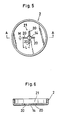
- Figs. 5 and 6 illustrate a second embodiment of the invention which includes an improved metal lid 2.
- This lid 2 has a dish-like shape and perforated with a center through bore 14 which is continuous with four cutouts 20 to define a cruciform bore 21 (opening) in plan view.
- a safety valve mechanism operating test was carried out on a cell having this improved metal lid 2.
- the cell having the metal lid 2 in the first embodiment was used for comparison purposes. Both of these cells had a 17mm outside diameter D and a 33.5mm height H, and their outer canisters 1 and metal lids 2 were formed of a 0.3mm stainless steel sheet (see Fig. 3).
- the through borer 14 in each lid had a 2.3mm diameter, and each of the four cutouts 20 in the second embodiment had a 1.8mm lenght L and a 0.5mm width M (see Fig. 5).
- Table 6 shows the results of this test, i.e. valve operating pressure measurements. In the test, the valve operating pressure was measured at room temperature and at 100°C, using cells of 1800mAh nominal capacity charged in a constant temperature oven with 6V constant voltage. The cells used were those having the same storage characteristics.
- the second embodiment has the same sealability as the first embodiment, the second embodiment is responsive to a very low valve operating pressure and the valve operating pressure therefor has a small range of variation with relation to temperature variations.
- Table 7 shows response time of the cells with the valve operating pressure raised to 30-40kg/cm2, that is the time taken from the point of time at which the pressure reaches the set value till the point of time at which the resin breaks and a valve operation takes place.
- the through bore 14 in the lid of the first embodiment had a 3.5mm diameter and that in the lid of the second embodiment had a 2.3mm diameter.
- the numbers of samples are 78 for the second embodiment and 284 for the first embodiment.
- the second embodiment has high valve operating precision with a short response time, i.e. excellent response, and a small response time distribution.
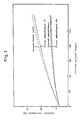
- Fig. 7 is a graph showing the results in comparison with the characteristics of the second known cell (Fig. 2).
- the solid line respresents the cell according to the second embodiment having a 2.3mm through bore diameter, a 1.8mm cutout length L and a 0.5mm cutout width M (Fig. 5)
- the two-dot and dash line represents a cell according to the first embodiment -1- having a 3.5mm through bore diameter
- the dot and dash line represents a cell according to the first embodiment -2- having a 2.3mm through bore diameter
- the broken line represents the second known cell shown in Table 5.
- the test was conducted at an atmospheric temperature of 60°C and a humidity of 90%.
- the test results prove that the second embodiment, while having the same valve operating pressure, 30-40kg/cm2 (2.94 x 10³ - 3.92 x 10³ KPa), as the first embodiment -1-, is effective with respect to the cell sealing in that it restrains the internal resistance rise by means of the opening of the metal lid which has a substantially diminished size for defining the cutouts.
- the first embodiment -2- having the same through bore in diameter size as the second embodiment is comparable with the latter with respect to the cell sealing.
- the second embodiment which includes the cutouts may be set to a lower valve operating pressure, and therefore may readily be provided with a desired safety valve mechanism.
- the enclosed cells according to the present invention have a safety valve mechanism of better characteristics than that of the known enclosed cells.
- the operating pressure for the safety valve mechanism of this invention is, as distinct from the prior art, variable by changing the adhesion thickness of the resin packing 3 with respect to the metal elements, i.e. metal lid 2 and negative terminal 5.
- Tables 8 and 9 show operating pressure characteristics obtained by changing the adhesion thickness T in Fig. 3 to 0.1mm, 0.2mm, 0.3mm and 0.4mm. In Fig. 3, dimension D1 is 4mm, D2 is 7mm, and D3 is 9mm.
- the test of Table 8 used polyamide 12 as the packing material and the test of Table 9 used modified polyprolylene.
- the packing 3 having the adhesive thickness T of about 0.4mm results in a low operating pressure, enabling an appropriate pressure setting.
- modified polypropylene which has a low material strength and a low adhesive strength than polyamide 12, further lowers the valve operating pressure by about 20% and hence provides for a safety valve of the cell having satisfactory functions.
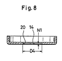
- the valve operating pressure may also be lowered for practical purposes by forming the metal lid 2 to be partially thin as shown in Fig. 8. More particularly, the metal lid 2 of Fig. 8 includes thin wall portions defining a circle of 9mm diameter D4 concentric with the cruciform bore 21 (opening). These thin wall portions have a 0.1mm wall thickness N1 (the remaining portion being 0.3mm thick as in the first and second embodiments). This construction is effective to stabilize the valve operating pressure to 28-35kg/cm2 (2.74-3.43 x 10³ KPa), which contributes toward improved quality.
- the present invention is not limited to the described embodiments.
- the foregoing embodiments employ the thermal fusion method for forming the packing by injection molding and for fusing the packing to the negative terminal and metal lid at the same time.
- the packing may be manufactured beforehand, set in the space between the dies together with the metal lid and negative terminal, and then heated and pressurized by suitable means to effect the thermal fusion. This has the advantage of permitting a general purpose packing to be used as it is for the cell.
- a packing is insert molded in the metal lid, then the negative terminal is inserted into the packing, and finally the metal lid and negative terminal are heated and pressurized by the hot press method or the like thereby to bond with each other.
- a packing material having no polar group cannot be used for lack of the adhesive property with respect to metals, but any resin may be used only if it has polar groups.
- modified polypropylene or polyamide 12 or polyamide 11 as described with the foregoing embodiments.
- polyamide 12 and polyamide 11 have the excellent rate proof water penetration, and are well suited where tight contact and high sealing performance are required of the packing.
- Modified polypropylene is suitable for setting the valve operating pressure low.
Landscapes
- Chemical & Material Sciences (AREA)
- Chemical Kinetics & Catalysis (AREA)
- Electrochemistry (AREA)
- General Chemical & Material Sciences (AREA)
- Gas Exhaust Devices For Batteries (AREA)
Description
- The present invention relates to an enclosed cell such as an alkaline storage battery or a lithium battery having a safety valve mechanism and methods of fabricating same. The safety valve mechanism is operable to release gas from inside the cell when an internal pressure of the cell rises to an excessive degree.
- With an enclosed cell such as an alkaline battery or a lithium battery, it is generally an important matter from the safety point of view that its opening is sealed tight. An insufficient sealing results in liquid leakage. In the case of lithium cell in particular, the insufficient sealing leads to a further problem of deterioration in cell performance. This arises from the reaction of the lithium anode with the moisture in ambient air entering the cell. The reaction produces a passivation film on the lithium anode surface which increases the internal resistance of the cell.
- Various cells have heretofore been proposed with a view to improvement in sealing reliability.
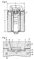
- Fig. 1 of the accompanying drawings illustrates one such example of enclosed cell, wherein the improvement resides in a hermetic seal structure comprising a glass or ceramic insulator a. More particularly, this enclosed cell comprises an outer canister b acting as one of the polar terminals, a metal lid c fused to the outer canister b such as by laser welding, and a cylindrical pin d inserted into and fixed to the insulator a to act as the other polar terminal. The outer canister b includes a thin wall portion e which breaks when the internal resistance of the cell rises as a result of misuse or in an abnormal environment. The internal pressure is released to the ambient through the breakage, thereby to prevent the cell from bursting.
- However, this hermetic seal structure generally is costly because the insulator a is formed of glass or ceramics. It is also difficult to control the thickness t of the thin wall portion e. This impedes valve operating pressure setting, which is contrary to full assurance of safety.
- Fig. 2 illustrates a second example of enclosed cell which is known from GB-A-2 138 200 and which is an enclosed cell according to the preamble part of
claim 1. To improve the sealing this cell discards the hermetic seal structure which is costly and involves difficulties from the point of view of manufacturing techique, in favor of using an insulating packing f formed of a resin (see the Japanese utility model application laid open under No. 60-22753). In this enclosed cell, a second terminal d having a T-shape section is inserted into the packing f and calked by means of a metal washer g fitted on a lower position of the termiral d. This example includes a metal lid c secured to an outer canister b by laser welding or the like as in the first known example. The resin packing f melts and forms an opening (not shown) when the internal pressure of the cell increases or the cell temperature rises to an excessive degree. The gas in the cell is released to the ambient through this opening, thereby to check the internal pressure increasing and prevent the cell from bursting. - In this enclosed cell, however, the washer g has an outside diameter g greater than the diameter i of a bore defined in the metal lid c, and the bore may be closed by the washer g when the terminal d moves in a direction of arrow j with a rise in the internal pressure of the cell. Thus, the washer g may obstruct the release of the gas from inside the cell. This cell fails to assure safety when used in a severe environment, for example at high temperature.
- An object of the present invention is to provide a enclosed cell assuring a high degree of safety, with a reliable sealing, which is simple in construction, and includes a safety valve mechanism having excellent operability.
- This object is achieved by an enclosed cell having the features given in
claim 1. - According to the construction, according to the invention, the resin packing adheres to the metal elements with a great adhesive strength after the packing is thermally fused thereto in proper conditions, which maintains a reliable sealing at normal times. This resin packing deforms or breaks to release gras from inside the cell on a short-circuit or other abnormal occasion when the cell becomes heated or its internal pressure rises to an excess. In other words, the resin packing acts as the safety valve mechanism and, as noted above, deforms or breaks to outwardly release gas from inside the cell when the internal pressure of the cell exceeds a predetermined value.
- This effect is promoted where the through bore is formed in the metal lid to be continuous with at least one cutout. The cutout renders the metal lid readily deformable in regions thereof adjacent the through bore as a result of an excessive pressure rise inside the cell. This permits the safety valve operating pressure to be controlled with ease, thereby improving the safety aspect more.
- In view of the sealing performance and other requirements, the packing material is selected from resins having polar groups, such as polyamide 11, polyamide 12, modified polypropylene and modified polyethylene.
- Another object of the invention is to provide a method of rationally fabricating an enclosed cell having a safety valve mechanism having an excellent operability as noted above.
- Accordingly, a method of fabricating an enclosed cell having a safety valve mechanism according to the invention comprises the steps given in
claim 2. - In the above fabricating method, the packing is formed by injection molding with the metal lid and polar terminal placed in a space surrounded by a first and a second dies. This permits the packing formation and thermal fusion to be carried out simultaneously, which leads to a simplified fabricating process and to low manufacturing cost.
- The safety valve operating pressure may be set to various values by changing the resin packing thickness, its area subjected to the pressure, and the kind, grade and the like of resin material for forming the packing. The safety valve operating pressure is also ajustable by increasing or decreasing the width, lenght and number of cutouts formed continuous with the through bore of the metal lid. Particularly the dimensions of the cutouts may readily be adjusted in the manufacturing process, which has the advantage of varying the valve operating pressure with ease.
- The enclosed cell constructed as above assures a high degree of safety and has excellent operational response since the cell is sealed reliably and its safety valve mechanism is properly operable under severe conditions. Moreover, this cell has a simple and inexpensive construction and hence an immense practical utility. The cell fabricating method is highly rationalized for low cost production.
- These and other objects or features of the present invention will become apparent from the following description of preferred embodiments thereof taken in conjunction with the accompanying drawings, in which:-
- Fig. 1 is a sectional view of a sealing portion of a first example of known enclosed cell,
- Fig. 2 is a sectional view of a sealing portion of a second example of known enclosed cell,
- Fig. 3 is a sectional view of an enclosed cell having a safety valve mechanism according to a first embodiment of the present invention,
- Fig. 4 is an explanatory view illustrating a fabricating process of a safety valve system for the cell shown in Fig. 3,
- Fig. 5 is a plan view of a metal lid according to a second embodiment of the invention,
- Fig. 6 is a section taken on line A-A of Fig. 5,
- Fig. 7 is a view showing storage characteristics of the enclosed cell according to the present invention, and
- Fig. 8 is a sectional view of a metal lid according to a further embodiment of the invention.
- In the following description, like parts are designated by like reference numbers throughout the several drawings.
- Fig. 3 is a sectional view of a manganese dioxide-lithium battery which is one example of enclosed cell according to the present invention. This battery comprises an
outer canister 1 acting as a positive terminal, ametal lid 2 approximately of a dish shape fused over an entire circumference to theouter canister 1 by laser welding or the like and defining a throughbore 14 centrally thereof, aninsulating packing 3 formed of a resin having polar groups such as modified polypropylene or polyamide 11, polyamide 12 or the like for adhering themetal lid 2, anegative terminal 5 having a substantially T-shaped section and extending through a center bore 4 of thepacking 3, and an electrode assembly 6. - The electrode assembly 6 includes a cathode having manganese dioxide as its active material, an anode having lithium as its active material, and a bag-like separator 9 interposed between the anode and
cathode 7, 8. The electrode assembly, together with an unillustrated electrolyte, constitutes generating elements. Theanode 7 is electrically connected to theouter canister 1 under a certain contact pressure, while the cathode 8 is electrically connected to thenegative terminal 5 through a negativepolar tab 10. Number 13 indicates an insulating sleeve for preventing short-circuit of the electrodes in the battery. - In order to provide excellent sealing, this enclosed cell has rigid junctions achieved by thermal fusion between the
metal lid 2 and insulatingpacking 3 and between theinsulating packing 3 andnegative terminal 5, respectively. - Fig. 4 illustrate a process of injection molding which is one example of means for thermally fusing these junctions.
Number 15 indicates an upper die andnumber 16 indicates a lower die. Polyamide 12 which has a particularly good adhesive property with respect to metals is employed for forming the insulatingpacking 3. In this drawing, themetal lid 2 andnegative terminal 5 are first placed in aspace 17 between the upper and lower dies 15, 16, and then polyamide 12 melted at 230°C is injected under a pressure of about 300kg/cm² (2.94 x 10⁴ KPa) into an injecting bore 18 defined in theupper die 15 as shown by arrows B. The injected polyamide 12 fills thespace 17 and forms a resin packing. In the course of hardening in this process, the molten polyamide 12 adheres tight to the metal elements, namely themetal lid 2 andnegative terminal 5, and becomes fused thereto. This process of fusing the packing to themetal lid 2 andnegative terminal 5 simultaneously with the packing formation, improves productivity and lowers manufacturing cost.Number 19 indicates heaters embedded in the dies 15, 16. Theseheaters 19 heat the dies 15, 16 which in turn heat thespace 17,negative terminal 5 andmetal lid 2 to a predetermined temperature. - Table 1 shows the results of a safety valve operating pressure test conducted on the first and second known enclosed cells noted hereinbefore and the cell according to the present invention (first embodiment) fabricated by the above thermal fusion process. Each cell had the outer canister and metal lid formed of a stainless steel sheet having a 0.3mm thickness. The thin wall portion e of the first known cell (shown in Fig. 1 ) was formed into a 0.1mm thickness t. The valve operating pressures were measured by sealing the cells with the generating elements excluded from the cells. The cells were internally pressurized from atmospheric pressure up to 100kg/cm² (9.8 x 10³ KPa) at the rate of 2kg/cm² (1.96 x 10² KPa) per second. The test was conducted at 110°C atmospheric temperature and by using 10 samples for each type of cell.

- The two remaining samples of the first known cell broke at the laser welded position under the pressure of about 70kg/cm².
- Table 2 shows the result of a similar test in which the cells were internally pressurized at the rate of 20kg/cm² (1.96 x 10³ KPa) per second. This test was conducted at the same atmospheric temperature and in respect of the same number of samples as in the foregoing test.

- The two remaining samples of the first known cell burst because of inoperative valves. The three remaining samples of the second known cell broke out at the weld junction between the outer canister and metal lid under the pressure of 70-80kg/cm² (6.86 x 10³ -7.84 x 10³ KPa). In the latter case, the valves operate when the pressure rises to 50kg/cm² (4.9 x 10³ KPa) but fail to cope with a further release of the internal gas at the higher pressures. As seen from Tables 1 and 2, it has been confirmed through the tests that the enclosed cell according to the present invention has its safety valve mechanism acting to prevent bursting of the cell even under severe conditions as above.
- Then the cells were tested by mounting therein the generating elements including the
anode 7 and cathode 8. The cell samples were charged with 6V first, and the safety valve of every sample operated to prevent bursting and other trouble. When the samples were charged with 12V, however, two samples of the first known cell and three of the second known cell burst though no sample of the cell according to this invention (first embodiment) burst. - A further, heating test was conducted by placing each
cell sample 5 cm from an acetylene burner. None of the cell samples according to this invention burst thanks to the safety valve mechanism coming into operation, but two samples of the first known cell and one sample of the second known cell burst. - Table 3 shows the results of a drop test carried out to compare the strengths of the enclosed cell according to this invention (first embodiment) and the first known cell having the hermetic seal which is considered to provide an excellent sealing. Thirty samples were used for each cell, and the number of leaking samples were counted after dropping them. The test was conducted by throwing each sample ten times in a selected direction from a height of 1.5m to a concrete surface. The hermetic seal had an insulator a (Fig. 1) formed of glass.

- As seen from Table 3, the first known cell must be handled with care since the insulator such as of glass or ceramics used in hermetic sealing is hard and brittle and therefore vulnerable to impact, whereas the first embodiment of the invention is easy to handle since it is sealed with the resin packing which is strong against impact. On the other hand, a helium leak test showed substantially the same leak value for the two types of cells. Table 4 shows its measurement results.

- Thus, the cell according to the first embodiment of the invention and the first known cell are equal with respect to the sealing performance under normal circumstances.
- Table 5 shows storage characteristics of the cells. The number of samples used was 100.

- In the case of enclosed cell, cell performance deteriorates after a long storage time due to the moisture of ambient air entering the cell. As seen from table 5, the enclosed cell according to this invention retains approximately the same internal resistance after a storage period as the first and second known cells, and remains just as well sealed as the prior art cells. Where lithium is used for the anode as in this manganese dioxide-lithium battery lithium ions in the cell react with silicone dioxide constituting the principal component of glass, thereby to promote disintegration of the glass. This is responsible for the four leaking samples of the first known samples. In contrast, the packing material used in the first embodiment of the invention does not react with lithium ions, and therefore no leakage takes place.
- The cell according to the first embodiment is well sealed as described above and can dispense with the washer mounted in the second known cell (Fig. 2), which means a reduction in the number of components. With the removal of the washer, a special safety valve structure is no longer required since the negative terminal will disengage from the cell by the gas pressure when, for example, the internal resistance of the cell rises under abnormal circumstances. Consequently, the invention has realized a cell having a simple construction and a high degree of safety.
- Figs. 5 and 6 illustrate a second embodiment of the invention which includes an
improved metal lid 2. Thislid 2 has a dish-like shape and perforated with a center through bore 14 which is continuous with fourcutouts 20 to define a cruciform bore 21 (opening) in plan view. - A safety valve mechanism operating test was carried out on a cell having this improved
metal lid 2. In this test the cell having themetal lid 2 in the first embodiment was used for comparison purposes. Both of these cells had a 17mm outside diameter D and a 33.5mm height H, and theirouter canisters 1 andmetal lids 2 were formed of a 0.3mm stainless steel sheet (see Fig. 3). The throughborer 14 in each lid had a 2.3mm diameter, and each of the fourcutouts 20 in the second embodiment had a 1.8mm lenght L and a 0.5mm width M (see Fig. 5). Table 6 shows the results of this test, i.e. valve operating pressure measurements. In the test, the valve operating pressure was measured at room temperature and at 100°C, using cells of 1800mAh nominal capacity charged in a constant temperature oven with 6V constant voltage. The cells used were those having the same storage characteristics.
- It will be understood from these results that, although the second embodiment has the same sealability as the first embodiment, the second embodiment is responsive to a very low valve operating pressure and the valve operating pressure therefor has a small range of variation with relation to temperature variations.
- Table 7 shows response time of the cells with the valve operating pressure raised to 30-40kg/cm², that is the time taken from the point of time at which the pressure reaches the set value till the point of time at which the resin breaks and a valve operation takes place. The through
bore 14 in the lid of the first embodiment had a 3.5mm diameter and that in the lid of the second embodiment had a 2.3mm diameter. The numbers of samples are 78 for the second embodiment and 284 for the first embodiment.
- These results prove that the second embodiment has high valve operating precision with a short response time, i.e. excellent response, and a small response time distribution.
- Next, the internal resistance of these cells was measured by 1KHz alternating current process and storage characteristics were compared. Fig. 7 is a graph showing the results in comparison with the characteristics of the second known cell (Fig. 2). In this drawing, the solid line respresents the cell according to the second embodiment having a 2.3mm through bore diameter, a 1.8mm cutout length L and a 0.5mm cutout width M (Fig. 5), the two-dot and dash line represents a cell according to the first embodiment -1- having a 3.5mm through bore diameter, the dot and dash line represents a cell according to the first embodiment -2- having a 2.3mm through bore diameter, and the broken line represents the second known cell shown in Table 5. The test was conducted at an atmospheric temperature of 60°C and a humidity of 90%. The test results prove that the second embodiment, while having the same valve operating pressure, 30-40kg/cm² (2.94 x 10³ - 3.92 x 10³ KPa), as the first embodiment -1-, is effective with respect to the cell sealing in that it restrains the internal resistance rise by means of the opening of the metal lid which has a substantially diminished size for defining the cutouts. On the other hand, the first embodiment -2- having the same through bore in diameter size as the second embodiment is comparable with the latter with respect to the cell sealing. However, the second embodiment which includes the cutouts may be set to a lower valve operating pressure, and therefore may readily be provided with a desired safety valve mechanism. Thus, it has been confirmed that in any case the enclosed cells according to the present invention have a safety valve mechanism of better characteristics than that of the known enclosed cells.
- Furthermore, it has been confirmed through a test conducted by Applicant that the operating pressure for the safety valve mechanism of this invention is, as distinct from the prior art, variable by changing the adhesion thickness of the resin packing 3 with respect to the metal elements, i.e.
metal lid 2 andnegative terminal 5. Tables 8 and 9 show operating pressure characteristics obtained by changing the adhesion thickness T in Fig. 3 to 0.1mm, 0.2mm, 0.3mm and 0.4mm. In Fig. 3, dimension D1 is 4mm, D2 is 7mm, and D3 is 9mm. The test of Table 8 used polyamide 12 as the packing material and the test of Table 9 used modified polyprolylene.

- As seen from Tables 8 and 9, the
packing 3 having the adhesive thickness T of about 0.4mm results in a low operating pressure, enabling an appropriate pressure setting. In the case of modified polypropylene, which has a low material strength and a low adhesive strength than polyamide 12, further lowers the valve operating pressure by about 20% and hence provides for a safety valve of the cell having satisfactory functions. - While the second embodiment is provided with the cruciform bore 21 (opening), it has been confirmed that the
bore 21 includingadditional cutouts 20 stabilizes the operating pressure even further. Table 10 shows a comparison in the valve operating pressure between the cruciform bore 21 (opening) and a bore (opening) having a shape of *.
- It will be understood from the above data that the bore (opening) having the * shape results in a reduced dispersion of operating pressures and a further improved safety valve of the cell.
- The valve operating pressure may also be lowered for practical purposes by forming the
metal lid 2 to be partially thin as shown in Fig. 8. More particularly, themetal lid 2 of Fig. 8 includes thin wall portions defining a circle of 9mm diameter D4 concentric with the cruciform bore 21 (opening). These thin wall portions have a 0.1mm wall thickness N1 (the remaining portion being 0.3mm thick as in the first and second embodiments). This construction is effective to stabilize the valve operating pressure to 28-35kg/cm² (2.74-3.43 x 10³ KPa), which contributes toward improved quality. - The present invention is not limited to the described embodiments. The foregoing embodiments employ the thermal fusion method for forming the packing by injection molding and for fusing the packing to the negative terminal and metal lid at the same time. Instead of this process, the packing may be manufactured beforehand, set in the space between the dies together with the metal lid and negative terminal, and then heated and pressurized by suitable means to effect the thermal fusion. This has the advantage of permitting a general purpose packing to be used as it is for the cell. As another fabricating process, a packing is insert molded in the metal lid, then the negative terminal is inserted into the packing, and finally the metal lid and negative terminal are heated and pressurized by the hot press method or the like thereby to bond with each other. These processes, however, require a vacuum drying step since the resin packing has a water absorption of about 1.5%. Generally, a metal surface has "O" and "OH" bonded thereto, and H₂O is hydrogen-bonded to the"O" and "OH". The resin forming the packing also is hydrogen-bonded to these elements. Since the hydrogen-bonding is weaker than the bonding of "O" and "OH" on the metal surface, the H₂O present between the metal surface and the resin having polar groups would impair good adhesion. It is therefore necessary to dehydrate the packing. Thus, the resin packing is dehydrated by vacuum drying it under a reduced pressure of 4mmHg and at 120°C for about two hours, for example. Then the negative terminal is inserted into the packing in dry atmosphere, which is followed by a hot press heating step for heating the metal lid and polar terminal at 200°C for two seconds, for example.
- A packing material having no polar group cannot be used for lack of the adhesive property with respect to metals, but any resin may be used only if it has polar groups. However, it is desirable to use modified polypropylene or polyamide 12 or polyamide 11 as described with the foregoing embodiments. As is well known, polyamide 12 and polyamide 11 have the excellent rate proof water penetration, and are well suited where tight contact and high sealing performance are required of the packing. Modified polypropylene is suitable for setting the valve operating pressure low.
Claims (3)
an outer canister (1) having an opening at one end thereof and acting as a first polar terminal,
a generating element disposed in said outer canister (1) and including an electrode assembly (7, 8) and an electrolyte,
a metal lid (2) fused to a peripheral edge of the opening of said outer canister (1) containing said generating element, said metal lid (2) defining a through bore (14) centrally thereof and
a second polar terminal (5) including a planar portion and
a pin component extending from a center of an undersurface of said planar portion, said pin component extending into said through bore (14) without contacting said through bore (14), and
a resin packing (3) having polar groups and being placed between said metal lid (2) and said second polar terminal (5) for sealing the cell interior gastight, characterized in that said packing (3) defines seals by thermal fusion thereof to said metal lid (2) and to a peripheral face of said pin component, that with said metal lid (2) is provided at least one cutout (20) and/or with portions having a reduced thickness adjacent to said through bore (14), whereby said packing (3) is deformable and/or breakable to release a gas when the internal pressure of the cell increases to excess.
placing the metal lid (2) defining the through bore (14), which is to be fused to the outer canister (1), and the polar terminal (5) in a space surrounded by a first die (15) and a second die (16),
heating said first and second dies (15,16) to a temperature below the resin melting point,
injecting molten resin having polar groups into said space, and hardening the molten resin into said resin packing (3) and thereby fastering it to said metal lid (2) and said polar terminal (5).
Applications Claiming Priority (6)
| Application Number | Priority Date | Filing Date | Title |
|---|---|---|---|
| JP115053/86 | 1986-05-20 | ||
| JP11505386 | 1986-05-20 | ||
| JP142910/86 | 1986-09-18 | ||
| JP14291086 | 1986-09-18 | ||
| JP32456/87 | 1987-03-05 | ||
| JP3245687 | 1987-03-05 |
Publications (3)
| Publication Number | Publication Date |
|---|---|
| EP0246590A2 EP0246590A2 (en) | 1987-11-25 |
| EP0246590A3 EP0246590A3 (en) | 1988-03-23 |
| EP0246590B1 true EP0246590B1 (en) | 1991-08-14 |
Family
ID=27287707
Family Applications (1)
| Application Number | Title | Priority Date | Filing Date |
|---|---|---|---|
| EP87107184A Expired - Lifetime EP0246590B1 (en) | 1986-05-20 | 1987-05-18 | Enclosed cell having safety valve mechanism and fabricating method of the same |
Country Status (2)
| Country | Link |
|---|---|
| EP (1) | EP0246590B1 (en) |
| DE (1) | DE3772099D1 (en) |
Cited By (1)
| Publication number | Priority date | Publication date | Assignee | Title |
|---|---|---|---|---|
| US7544439B2 (en) | 2005-04-27 | 2009-06-09 | The Gillette Company | Venting water-tight battery-operated devices |
Families Citing this family (10)
| Publication number | Priority date | Publication date | Assignee | Title |
|---|---|---|---|---|
| JP5213030B2 (en) * | 2008-04-17 | 2013-06-19 | 日立マクセル株式会社 | Sealed battery manufacturing method and sealed battery |
| KR101218370B1 (en) * | 2012-11-09 | 2013-01-03 | 주식회사 비츠로셀 | Lithium battery with safety |
| CN109192889B (en) * | 2018-08-22 | 2024-01-26 | 珠海微矩实业有限公司 | Micro battery |
| CN110391478B (en) * | 2019-08-02 | 2020-09-11 | 湖南科技大学 | Lithium battery safety device |
| KR20210021842A (en) * | 2019-08-19 | 2021-03-02 | 삼성에스디아이 주식회사 | Rechargeable battery |
| DE102019220391A1 (en) * | 2019-12-20 | 2021-06-24 | Volkswagen Aktiengesellschaft | Emergency degassing arrangement for the emergency degassing of a battery in an electrically powered motor vehicle |
| TW202141840A (en) * | 2020-03-11 | 2021-11-01 | 南韓商Lg化學股份有限公司 | Button type secondary battery |
| KR20210157726A (en) * | 2020-06-22 | 2021-12-29 | 삼성에스디아이 주식회사 | Rechargeable battery |
| KR20220003396A (en) * | 2020-07-01 | 2022-01-10 | 삼성에스디아이 주식회사 | Rechargeable battery |
| EP4318747A1 (en) * | 2021-03-31 | 2024-02-07 | Ningde Amperex Technology Ltd. | Battery and electronic device |
Family Cites Families (7)
| Publication number | Priority date | Publication date | Assignee | Title |
|---|---|---|---|---|
| US3939011A (en) * | 1973-01-05 | 1976-02-17 | P. R. Mallory & Co. Inc. | Lithium cell with internal automatic safety controls |
| US4053691A (en) * | 1976-10-01 | 1977-10-11 | P. R. Mallory & Co., Inc. | Porous light weight battery filler |
| US4127702A (en) * | 1977-10-11 | 1978-11-28 | Catanzarite Vincent Owen | Self-venting battery |
| US4224736A (en) * | 1978-08-07 | 1980-09-30 | Esb Inc. | Process for sealing electrochemical cells |
| JPS56118270A (en) * | 1980-02-20 | 1981-09-17 | Hitachi Maxell Ltd | Thin battery |
| US4629665A (en) * | 1983-02-07 | 1986-12-16 | Sanyo Electric Co., Ltd. | Cylindrical battery |
| BE900022A (en) * | 1983-07-11 | 1984-10-15 | Duracell Int | ELECTROCHEMICAL CELLS. |
-
1987
- 1987-05-18 EP EP87107184A patent/EP0246590B1/en not_active Expired - Lifetime
- 1987-05-18 DE DE8787107184T patent/DE3772099D1/en not_active Expired - Fee Related
Cited By (2)
| Publication number | Priority date | Publication date | Assignee | Title |
|---|---|---|---|---|
| US7544439B2 (en) | 2005-04-27 | 2009-06-09 | The Gillette Company | Venting water-tight battery-operated devices |
| US7846570B2 (en) | 2005-04-27 | 2010-12-07 | The Gillette Company | Venting water-tight battery-operated devices |
Also Published As
| Publication number | Publication date |
|---|---|
| EP0246590A2 (en) | 1987-11-25 |
| DE3772099D1 (en) | 1991-09-19 |
| EP0246590A3 (en) | 1988-03-23 |
Similar Documents
| Publication | Publication Date | Title |
|---|---|---|
| US4804593A (en) | Enclosed cell having safety valve mechanism and fabricating method of the same | |
| KR100386394B1 (en) | Battery with explosion-proof function | |
| KR100324863B1 (en) | Explosion-proof seal plate for enclosed type cell and production method thereof | |
| US5188909A (en) | Electrochemical cell with circuit disconnect device | |
| US4028478A (en) | Safety switch for sealed galvanic cells | |
| US5376467A (en) | Organic electrolyte battery | |
| EP0246590B1 (en) | Enclosed cell having safety valve mechanism and fabricating method of the same | |
| US5227261A (en) | Cylindrical electrochemical cells with a diaphragm seal | |
| US4127702A (en) | Self-venting battery | |
| US4358514A (en) | Header device for electrochemical cells | |
| KR101054748B1 (en) | Secondary battery cap assembly with excellent electrolyte sealing | |
| US5783329A (en) | Accumulator with plastic casing | |
| JPH06196150A (en) | Battery and manufacture of battery | |
| US4869978A (en) | Cylindrical alkaline batteries | |
| US4486514A (en) | Hermetically sealed galvanic cell having safety vent construction | |
| US3484301A (en) | Electrical cell vent valve | |
| JP3667835B2 (en) | Sealed storage battery | |
| JPH06196140A (en) | Explosion-proof type sealed battery | |
| US4008354A (en) | Pressure vent-sealed primary and secondary alkaline cells | |
| JPH09115498A (en) | Sealed storage battery | |
| WO1989004068A1 (en) | Alkali metal energy conversion device and method of construction | |
| JP3649792B2 (en) | Sealed battery | |
| JP2952033B2 (en) | Alkaline batteries | |
| JPH0636209U (en) | Sealed battery | |
| KR20070056492A (en) | Secondary battery containing safety member of bimetal base |
Legal Events
| Date | Code | Title | Description |
|---|---|---|---|
| PUAI | Public reference made under article 153(3) epc to a published international application that has entered the european phase |
Free format text: ORIGINAL CODE: 0009012 |
|
| AK | Designated contracting states |
Kind code of ref document: A2 Designated state(s): CH DE FR GB LI |
|
| PUAL | Search report despatched |
Free format text: ORIGINAL CODE: 0009013 |
|
| AK | Designated contracting states |
Kind code of ref document: A3 Designated state(s): CH DE FR GB LI |
|
| 17P | Request for examination filed |
Effective date: 19880331 |
|
| 17Q | First examination report despatched |
Effective date: 19890726 |
|
| GRAA | (expected) grant |
Free format text: ORIGINAL CODE: 0009210 |
|
| AK | Designated contracting states |
Kind code of ref document: B1 Designated state(s): CH DE FR GB LI |
|
| ET | Fr: translation filed | ||
| REF | Corresponds to: |
Ref document number: 3772099 Country of ref document: DE Date of ref document: 19910919 |
|
| PLBE | No opposition filed within time limit |
Free format text: ORIGINAL CODE: 0009261 |
|
| STAA | Information on the status of an ep patent application or granted ep patent |
Free format text: STATUS: NO OPPOSITION FILED WITHIN TIME LIMIT |
|
| 26N | No opposition filed | ||
| PGFP | Annual fee paid to national office [announced via postgrant information from national office to epo] |
Ref country code: FR Payment date: 20000510 Year of fee payment: 14 |
|
| PGFP | Annual fee paid to national office [announced via postgrant information from national office to epo] |
Ref country code: DE Payment date: 20000515 Year of fee payment: 14 |
|
| PGFP | Annual fee paid to national office [announced via postgrant information from national office to epo] |
Ref country code: GB Payment date: 20000517 Year of fee payment: 14 |
|
| PGFP | Annual fee paid to national office [announced via postgrant information from national office to epo] |
Ref country code: CH Payment date: 20000526 Year of fee payment: 14 |
|
| PG25 | Lapsed in a contracting state [announced via postgrant information from national office to epo] |
Ref country code: GB Free format text: LAPSE BECAUSE OF NON-PAYMENT OF DUE FEES Effective date: 20010518 |
|
| PG25 | Lapsed in a contracting state [announced via postgrant information from national office to epo] |
Ref country code: LI Free format text: LAPSE BECAUSE OF NON-PAYMENT OF DUE FEES Effective date: 20010617 Ref country code: CH Free format text: LAPSE BECAUSE OF NON-PAYMENT OF DUE FEES Effective date: 20010617 |
|
| GBPC | Gb: european patent ceased through non-payment of renewal fee |
Effective date: 20010518 |
|
| REG | Reference to a national code |
Ref country code: CH Ref legal event code: PL |
|
| PG25 | Lapsed in a contracting state [announced via postgrant information from national office to epo] |
Ref country code: FR Free format text: LAPSE BECAUSE OF NON-PAYMENT OF DUE FEES Effective date: 20020131 |
|
| PG25 | Lapsed in a contracting state [announced via postgrant information from national office to epo] |
Ref country code: DE Free format text: LAPSE BECAUSE OF NON-PAYMENT OF DUE FEES Effective date: 20020301 |