EP0246590A2 - Geschlossene Zelle mit Sicherheitsventilanordnung und Verfahren zu ihrer Herstellung - Google Patents
Geschlossene Zelle mit Sicherheitsventilanordnung und Verfahren zu ihrer Herstellung Download PDFInfo
- Publication number
- EP0246590A2 EP0246590A2 EP87107184A EP87107184A EP0246590A2 EP 0246590 A2 EP0246590 A2 EP 0246590A2 EP 87107184 A EP87107184 A EP 87107184A EP 87107184 A EP87107184 A EP 87107184A EP 0246590 A2 EP0246590 A2 EP 0246590A2
- Authority
- EP
- European Patent Office
- Prior art keywords
- cell
- metal lid
- packing
- polar
- resin
- Prior art date
- Legal status (The legal status is an assumption and is not a legal conclusion. Google has not performed a legal analysis and makes no representation as to the accuracy of the status listed.)
- Granted
Links
Images


Classifications
-
- H—ELECTRICITY
- H01—ELECTRIC ELEMENTS
- H01M—PROCESSES OR MEANS, e.g. BATTERIES, FOR THE DIRECT CONVERSION OF CHEMICAL ENERGY INTO ELECTRICAL ENERGY
- H01M50/00—Constructional details or processes of manufacture of the non-active parts of electrochemical cells other than fuel cells, e.g. hybrid cells
- H01M50/10—Primary casings; Jackets or wrappings
- H01M50/172—Arrangements of electric connectors penetrating the casing
-
- H—ELECTRICITY
- H01—ELECTRIC ELEMENTS
- H01M—PROCESSES OR MEANS, e.g. BATTERIES, FOR THE DIRECT CONVERSION OF CHEMICAL ENERGY INTO ELECTRICAL ENERGY
- H01M50/00—Constructional details or processes of manufacture of the non-active parts of electrochemical cells other than fuel cells, e.g. hybrid cells
- H01M50/10—Primary casings; Jackets or wrappings
- H01M50/183—Sealing members
- H01M50/186—Sealing members characterised by the disposition of the sealing members
- H01M50/188—Sealing members characterised by the disposition of the sealing members the sealing members being arranged between the lid and terminal
-
- H—ELECTRICITY
- H01—ELECTRIC ELEMENTS
- H01M—PROCESSES OR MEANS, e.g. BATTERIES, FOR THE DIRECT CONVERSION OF CHEMICAL ENERGY INTO ELECTRICAL ENERGY
- H01M50/00—Constructional details or processes of manufacture of the non-active parts of electrochemical cells other than fuel cells, e.g. hybrid cells
- H01M50/10—Primary casings; Jackets or wrappings
- H01M50/183—Sealing members
- H01M50/19—Sealing members characterised by the material
- H01M50/193—Organic material
-
- H—ELECTRICITY
- H01—ELECTRIC ELEMENTS
- H01M—PROCESSES OR MEANS, e.g. BATTERIES, FOR THE DIRECT CONVERSION OF CHEMICAL ENERGY INTO ELECTRICAL ENERGY
- H01M50/00—Constructional details or processes of manufacture of the non-active parts of electrochemical cells other than fuel cells, e.g. hybrid cells
- H01M50/30—Arrangements for facilitating escape of gases
- H01M50/342—Non-re-sealable arrangements
-
- H—ELECTRICITY
- H01—ELECTRIC ELEMENTS
- H01M—PROCESSES OR MEANS, e.g. BATTERIES, FOR THE DIRECT CONVERSION OF CHEMICAL ENERGY INTO ELECTRICAL ENERGY
- H01M50/00—Constructional details or processes of manufacture of the non-active parts of electrochemical cells other than fuel cells, e.g. hybrid cells
- H01M50/30—Arrangements for facilitating escape of gases
- H01M50/375—Vent means sensitive to or responsive to temperature
-
- Y—GENERAL TAGGING OF NEW TECHNOLOGICAL DEVELOPMENTS; GENERAL TAGGING OF CROSS-SECTIONAL TECHNOLOGIES SPANNING OVER SEVERAL SECTIONS OF THE IPC; TECHNICAL SUBJECTS COVERED BY FORMER USPC CROSS-REFERENCE ART COLLECTIONS [XRACs] AND DIGESTS
- Y02—TECHNOLOGIES OR APPLICATIONS FOR MITIGATION OR ADAPTATION AGAINST CLIMATE CHANGE
- Y02E—REDUCTION OF GREENHOUSE GAS [GHG] EMISSIONS, RELATED TO ENERGY GENERATION, TRANSMISSION OR DISTRIBUTION
- Y02E60/00—Enabling technologies; Technologies with a potential or indirect contribution to GHG emissions mitigation
- Y02E60/10—Energy storage using batteries
Definitions
- the present invention relates to an enclosed cell such as an alkaline storage battery or a lithium battery having a safety valve mechanism and methods of fabricating same.
- the safety valve mechanism is operable to release gas from inside the cell when an internal pressure of the cell rises to an excessive degree.
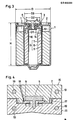
- Fig. 1 of the accompanying drawings illustrates one such example of enclosed cell, wherein the improvement resides in a hermetic seal structure comprising a glass or ceramic insulator a. More particularly, this enclosed cell comprises an outer canister b acting as one of the polar terminals, a metal lid c fused to the outer canister b such as by laser welding, and a cylindrical pin d inserted into and fixed to the insulator a to act as the other polar terminal.
- the outer canister b includes a thin wall portion e which breaks when the internal resistance of the cell rises as a result of misuse or in an abnormal environment. The internal pressure is released to the ambient through the breakage, thereby to prevent the cell from bursting.
- this hermetic seal structure generally is costly because the insulator a is formed of glass or ceramics. It is also difficult to control the thickness t of the thin wall portion e. This impedes valve operating pressure setting, which is contrary to full assurance of safety.
- Fig. 2 illustrates a second example of enclosed cell so far proposed.
- this cell discards the hermetic seal structure which is costly and involves difficulties from the point of view of manufacturing techique, in favor of using an insulating packing f formed of a resin (see the Japanese utility model application laid open under No. 60-22753).
- a second-terminal d having a T-shape section is inserted into the packing f and calked by means of a metal washer g fitted on a lower position of the terminal d.
- This example includes a metal lid c secured to an outer canister b by laser welding or the like as in the first known example.
- the resin packing f melts and forms an opening (not shown) when the internal pressure of the cell increases or the cell temperature rises to an excessive degree.
- the gas in the cell is released to the ambient through this opening, thereby to check the internal pressure increasing and prevent the cell from bursting.
- the washer g has an outside diameter g greater than the diameter i of a bore defined in the metal lid c, and the bore may be closed by the washer g when the terminal d moves in a direction of arrow j with a rise in the internal pressure of the cell.
- the washer g may obstruct the release of the gas from inside the cell.
- a primary object of the present invention is to provide a enclosed cell assuring a high degree of safety, with a reliable sealing, simple in construction, and including a safety valve mechanism having excellent operability.
- an enclosed cell having a safety valve mechanism comprises a generator including an electrode assembly and an electrolyte, an outer canister acting as a first polar terminal, a metal lid fused to the outer canister, a resin packing having polar groups and placed at an opening (including a through bore) defined in the metal lid, and a second polar terminal inserted into the packing, wherein the packing defines seals by thermal fusion thereof to the metal lid and the second polar terminal, respectively.
- the resin packing adheres to the metal elements with a great adhesive strength after the packing is thermally fused thereto in proper conditions, which maintains a reliable sealing at normal times.
- This resin packing deforms or breaks to release gas from inside the cell on a short-circuit or other abnormal occasion when the cell becomes heated or its internal pressure rises to an excess.
- the resin packing acts as the safety valve mechanism and, as noted above, deforms or breaks to outwardly release gas from inside the cell when the internal pressure of the cell exceeds a predetermined value.
- the through bore is formed in the metal lid to be continuous with at least one cutout.
- the cutout renders the metal lid readily deformable in regions thereof adjacent the through bore as a result of an excessive pressure rise inside the cell. This permits the safety valve operating pressure to be controlled with ease, thereby improving the safety aspect more.
- the packing material is selected from resins having polar groups, such as polyamide 11, polyamide 12, modified polypropylene and modified polyethylene.
- Another object of the invention is to provide methods of rationally fabricating an enclosed cell having a safety valve mechanism having an excellent operability as noted above.
- a method of fabricating an enclosed cell having a safety valve mechanism comprises the steps of placing a metal lid, which is to be fused to an outer canister, and a polar terminal in a space surrounded by a first die and a second die, heating the first and second dies to a temperature below a resin melting point, injecting molten resin into the space, and allowing the molten resin to harden into a resin packing and at the same to be thermally fused to the metal lid and the polar terminal.
- the packing is formed by injection molding with the metal lid and polar terminal placed in a space surrounded by a first and a second dies. This permits the packing formation and thermal fusion to be carried out simultaneously, which leads to a simplified fabricating process and to low manufacturing cost.
- the enclosed cell may be fabricated by other methods according to the present invention.
- One of them comprises the steps of setting the metal lid, resin packing and polar terminal in position in the space surrounded by the first and second dies, and heating and pressurizing the metal lid and polar terminal to thermally fuse the resin packing to the metal lid and polar terminal.
- Another method comprises the steps of injecting the resin packing onto the metal lid first, then attaching the polar terminal to the resin packing, and thermally fusing the resin packing on the polar terminal.
- the safety valve operating pressure may be set to various values by changing the resin packing thickness, its area subjected to the pressure, and the kind, grade and the like of resin material for forming the packing.
- the safety valve operating pressure is also ajustable by increasing or decreasing the width, length and number of cutouts formed countinous with the through bore of the metal lid. Particularly the dimensions of the cutouts may readily be adjusted in the manufacturing process, which has the advantage of varying the valve operating pressure with ease.
- the enclosed cell constructed as above assures a high degree of safety and has excellent operational response since the cell is sealed reliably and its safety valve mechanism is properly operable under severe conditions. Moreover, this cell has a simple and inexpensive construction and hence an immense practical utility.
- the cell fabricating methods are highly rationalized for low cost production.
- Fig. 3 is a sectional view of a manganese dioxide-lithium battery which is one example of enclosed cell according to the present invention.
- This battery comprises an outer canister 1 acting as a positive terminal, a metal lid 2 approximately of a dish shape fused over an entire circumference to the outer canister 1 by laser welding or the like and defining a through bore 14 centrally thereof, an insulating packing 3 formed of a resin having polar groups such as modified polypropylene or polyamide 11, polyamide 12 or the like for adhering the metal lid 2, a negative terminal 5 having a substantially T-shaped section and extending through a center bore 4 of the packing 3, and an electrode assembly 6.
- the electrode assembly 6 includes an anode 7 having manganese dioxide as its active material, a cathode 8 having lithium as its active material, and a bag-like separator 9 interposed between the anode and cathode 7, 8.
- the electrode assembly together with an unillustrated electrolyte, constitutes generating elements.
- the anode 7 is electrically connected to the outer canister 1 under a certain contact pressure, while the cathode 8 is electrically connected to the negative terminal 5 through a negative polar tab 10.
- Number 13 indicates an insulating sleeve for preventing short-circuit of the electrodes in the battery.
- this enclosed cell has rigid junctions achieved by thermal fusion between the metal lid 2 and insulating packing 3 and between the insulating packing 3 and negative terminal 5, respectively.
- Fig. 4 illustrate a process of injection molding which is one example of means for thermally fusing these junctions.
- Number 15 indicates an upper die and number 16 indicates a lower die.
- Polyamide 12 which has a particularly good adhesive property with respect to metals is employed for forming the insulating packing 3.
- the metal lid 2 and negative terminal 5 are first placed in a space 17 between the upper and lower dies 15, 16, and then polyamide 12 melted at 230 o C is injected under a pressure of about 300kg/cm into an injecting bore 18 defined in the upper die 15 as shown by arrows B.
- the injected polyamide 12 fills the space 17 and forms a resin packing.
- Number 19 indicates heaters embedded in the dies 15, 16. These heaters 19 heat the dies 15, 16 which in turn heat the space 17, negative terminal 5 and metal lid 2 to a predetermined temperature.
- Table 1 shows the results of a safety valve operating pressure test conducted on the first and second known enclosed cells noted hereinbefore and the cell according to the present invention (first embodiment) fabricated by the above thermal fusion process.
- Each cell had the outer canister and metal lid formed of a stainless steel sheet having a 0.3mm thickness.
- the thin wall portion e of the first known cell (shown in Fig. 1) was formed into a 0.1 mm thickness t.
- the valve operating pressures were measured by sealing the cells with the generating elements excluded from the cells.
- the cells were internally pressurized from atmospheric pressure up to 100kg/cm 2 at the rate of 2kg/cm 2 per second. The test was conducted at 110°C atmospheric temperature and by using 10 samples for each type of cell.
- the two remaining samples of the first known cell broke at the laser welded position under the pressure of about 70kg/cm 2 .
- Table 2 shows the result of a similar test in which the cells were internally pressurized at the rate of 20kg/cm x per second. This test was conducted at the same atmospheric temperature and in respect of the same number of samples as in the foregoing test.
- the cells were tested by mounting therein the generating elements including the anode 7 and cathode 8.
- the cell samples were charged with 6V first, and the safety valve of every sample operated to prevent bursting and other trouble.
- the samples were charged with 12V, however, two samples of the first known cell and three of the second known cell burst though no sample of the cell according to this invention (first embodiment) burst.
- a further, heating test was conducted by placing each cell sample 5 cm from an acetylene burner. None of the cell samples according to this invention burst thanks to the safety valve mechanism coming into operation, but two samples of the first known cell and one sample of the second known cell burst.
- Table 3 shows the results of a drop test carried out to compare the strengths of the enclosed cell according to this invention (first embodiment) and the first known cell having the hermetic seal which is considered to provide an excellent sealing. Thirty samples were used for each cell, and the number of leaking samples were counted after dropping them. The test was conducted by throwing each sample ten times in a selected direction from a height of 1.5m to a concrete surface.
- the hermetic seal had an insulator a (Fig. 1) formed of glass.
- the first known cell must be handled with care since the insulator such as of glass or ceramics used in hermetic sealing is hard and brittle and therefore vulnerable to impact, whereas the first embodiment of the invention is easy to handle since it is sealed with the resin packing which is strong against impact.
- a helium leak test showed substantially the same leak value for the two types of cells. Table 4 shows its measurement results.
- the cell according to the first embodiment of the invention and the first known cell are equal with respect to the sealing performance under normal circumstances.
- Table 5 shows storage characteristics of the cells. The number of samples used was 100.
- the enclosed cell In the case of enclosed cell, cell performance deteriorates after a long storage time due to the moisture of ambient air entering the cell. As seen from Table 5, the enclosed cell according to this invention retains approximately the same internal resistance after a storage period as the first and second known cells, and remains just as well sealed as the prior art cells.
- lithium is used for the cathode as in this manganese dioxide-lithium battery
- lithium ions in the cell react with silicone dioxide constituting the principal component of glass, thereby to promote disintegration of the glass. This is responsible for the four leaking samples of the first known samples.
- the packing material used in the first embodiment of the invention does not react with lithium ions, and therefore no leakage takes place.
- the cell according to the first embodiment is well sealed as described above and can dispense with the washer mounted in the second known cell (Fig. 2), which means a reduction in the number of components.
- Fig. 2 the second known cell
- a special safety valve structure is no longer required since the negative terminal will disengage from the cell by the gas pressure when, for example, the internal resistance of the cell rises under abnormal circumstances. Consequently, the invention has realized a cell having a simple construction and a high degree of safety.
- Figs. 5 and 6 illustrate a second embodiment of the invention which includes an improved metal lid 2.
- This lid 2 has a dish-like shape and perforated with a center through bore 14 which is continuous with four cutouts 20 to define a cruciform bore 21 (opening) in plan view.
- a safety valve mechanism operating test was carried out on a cell having this improved metal lid 2.
- the cell having the metal lid 2 in the first embodiment was used for comparison purposes. Both of these cells had a 17mm outside diameter D and a 33.5mm height H, and their outer canisters 1 and metal lids 2 were formed of a 0.3mm stainless steel sheet (see Fig. 3).
- the through bore 14 in each lid had a 2.3mm diameter, and each of the four cutouts 20 in the second embodiment had a 1.8mm length L and a 0.5mm width M (see Fig. 5).
- Table 6 shows the results of this test, i.e. valve operating pressure measurements.
- the valve operating pressure was measured at room temperature and at 100°C, using cells of 1800mAh nominal capacity charged in a constant temperature oven with 6V constant voltage. The cells used were those having the same storage characteristics.
- the second embodiment has the same sealability as the first embodiment, the second embodiment is responsive to a very low valve operating pressure and the valve operating pressure therefor has a small range of variation with relation to temperature variations.
- Table 7 shows response time of the cells with the valve operating pressure raised to 30-40kg/cm 2 , that is the time taken from the point of time at which the pressure reaches the set value till the point of time at which the resin breaks and a valve operation takes place.
- the through bare it in the lid of the first embodiment had a 3.5 mm diameter and that in the lid of the second embodiment had a 2.3mm diameter.
- the numbers of samples are 78 or the second 5 embodiment and 284 for the first embodiment.
- the second embodiment has high valve operating precision with a short response time, i.e. excellent response, and a samll response time distribution.
- Fig. 7 is a graph showing the results in comparison with the characteristics of the second known cell (Fig. 2).
- the solid line represents the cell according to the second embodiment having a 2.3mm through bore diameter, a 1.8mm cutout length L and a 0.5mm cutout width M (Fig. 5)
- the two-dot and dash line represents a cell according to the first embodiment -1- having a 3.5mm through bore diameter
- the dot and dash line represents a cell according to the first embodiment -2- having a 2.3mm through bore diameter
- the broken line represents the second known cell shown in Table 5.
- the test was conducted at an atmospheric temperature of 60°C and a humidity of 90 % .
- the test results prove that the second embodiment, while having the same valve operating pressure, 30-40kg/cm 2 , as the first embodiment -1-, is effective with respect to the cell sealing in that it restrains the internal resistance rise by means of the opening of the metal lid which has a substantially diminished size for defining the cutouts.
- the first embodiment -2- having the same through bore in diameter size as the second embodiment is comparable with the latter with respect to the cell sealing.
- the second embodiment which includes the cutouts may be set to a lower valve operating pressure, and therefore may readily be provided with a desired safety valve mechanism.
- the enclosed cells according to the present invention have a safety valve mechanism of better characteristics than that of the known enclosed cells.
- the operating pressure for the safety valve mechanism of this invention is, as distinct from the prior art, variable by changing the adhesion thickness of the resin packing 3 with respect to the metal elements, i.e. metal lid 2 and negative terminal 5.
- Tables 8 and 9 show operating pressure characteristics obtained by changing the adhesion thickness T in Fig. 3 to 0.1mm, 0.2mm, 0.3mm and 0.4mm. In Fig. 3, dimension D1 is 4mm, D2 is 7mm, and D3 is 9mm.
- the test of Table 8 used polyamide 12 as the packing material and the test of Table 9 used modified polypropylene.
- the packing 3 having the adhesive thickness T of about 0.4mm results in a low operating pressure, enabling an appropriate pressure setting.
- modified polypropylene which has a low material strength and a low adhesive strength than polyamide 12, further lowers the valve operating pressure by about 20% and hence provides for a safety valve of the cell having satisfactory functions.
- the valve operating pressure may also be lowered for practical purposes by forming the metal lid 2 to be partially thin as shown in Fig. 8. More particularly, the metal lid 2 of Fig. 8 includes thin wall portions defining a circle of 9mm diameter D4 concentric with the cruciform bore 21 (opening). These thin wall portions have a 0.1mm wall thickness N 1 (the remaining portion being 0.3mm thick as in the first and second embodiments). This construction is effective to stabilize the valve operating pressure to 28-3 5 kg/cm', which contributes toward improved quality.
- the present invention is not limited to the described embodiments.
- the foregoing embodiments employ the thermal fusion method for forming the packing by injection molding and for fusing the packing to the negative terminal and metal lid at the same time.
- the packing may be manufactured beforehand, set in the space between the dies together with the metal lid and negative terminal, and then heated and pressurized by suitable means to effect the thermal fusion. This has the advantage of permitting a general purpose packing to be used as it is for the cell.
- a packing is insert molded in the metal lid, then the negative terminal is inserted into the packing, and finally the metal lid and negative terminal are heated and pressurized by the hot press method or the like thereby to bond with each other.
- a packing material having no polar group cannot be used for lack of the adhesive property with respect to metals, but any resin may be used only if it has polar groups.
- modified polypropylene or polyamide 12 or polyamide 11 as described with the foregoing embodiments.
- polyamide 12 and polyamide 11 have the excellent rate proof water penetration, and are well suited where tight contact and high sealing performance are required of the packing.
- Modified polypropylene is suitable for setting the valve operating pressure low.
Landscapes
- Chemical & Material Sciences (AREA)
- Chemical Kinetics & Catalysis (AREA)
- Electrochemistry (AREA)
- General Chemical & Material Sciences (AREA)
- Gas Exhaust Devices For Batteries (AREA)
Applications Claiming Priority (6)
| Application Number | Priority Date | Filing Date | Title |
|---|---|---|---|
| JP115053/86 | 1986-05-20 | ||
| JP11505386 | 1986-05-20 | ||
| JP14291086 | 1986-09-18 | ||
| JP142910/86 | 1986-09-18 | ||
| JP32456/87 | 1987-03-05 | ||
| JP3245687 | 1987-03-05 |
Publications (3)
| Publication Number | Publication Date |
|---|---|
| EP0246590A2 true EP0246590A2 (de) | 1987-11-25 |
| EP0246590A3 EP0246590A3 (en) | 1988-03-23 |
| EP0246590B1 EP0246590B1 (de) | 1991-08-14 |
Family
ID=27287707
Family Applications (1)
| Application Number | Title | Priority Date | Filing Date |
|---|---|---|---|
| EP87107184A Expired - Lifetime EP0246590B1 (de) | 1986-05-20 | 1987-05-18 | Geschlossene Zelle mit Sicherheitsventilanordnung und Verfahren zu ihrer Herstellung |
Country Status (2)
| Country | Link |
|---|---|
| EP (1) | EP0246590B1 (de) |
| DE (1) | DE3772099D1 (de) |
Cited By (12)
| Publication number | Priority date | Publication date | Assignee | Title |
|---|---|---|---|---|
| CN101562238A (zh) * | 2008-04-17 | 2009-10-21 | 日立麦克赛尔株式会社 | 密封电池的制造方法 |
| EP2731162A1 (de) * | 2012-11-09 | 2014-05-14 | Vitzrocell Co., Ltd. | Lithiumbatterie mit hervorragender Sicherheit |
| CN109192889A (zh) * | 2018-08-22 | 2019-01-11 | 珠海微矩实业有限公司 | 一种微型电池 |
| CN110391478A (zh) * | 2019-08-02 | 2019-10-29 | 湖南科技大学 | 一种锂电池安全装置 |
| CN111710803A (zh) * | 2020-06-24 | 2020-09-25 | 深圳市格瑞普电池有限公司 | 扣式锂离子电池及壳体 |
| CN112467186A (zh) * | 2019-08-19 | 2021-03-09 | 三星Sdi株式会社 | 可再充电电池 |
| CN113013544A (zh) * | 2019-12-20 | 2021-06-22 | 大众汽车股份公司 | 用于电驱动的机动车的蓄电池的紧急排气的紧急排气装置 |
| CN113826250A (zh) * | 2021-03-31 | 2021-12-21 | 宁德新能源科技有限公司 | 电池及电子装置 |
| CN113903967A (zh) * | 2020-06-22 | 2022-01-07 | 三星Sdi株式会社 | 可再充电电池 |
| CN114641881A (zh) * | 2020-07-01 | 2022-06-17 | 三星Sdi株式会社 | 可再充电电池 |
| CN115210942A (zh) * | 2020-03-11 | 2022-10-18 | 株式会社Lg新能源 | 纽扣型二次电池 |
| US12555852B2 (en) | 2020-02-03 | 2026-02-17 | Samsung Sdi Co., Ltd. | Rechargeable battery |
Families Citing this family (1)
| Publication number | Priority date | Publication date | Assignee | Title |
|---|---|---|---|---|
| US7544439B2 (en) | 2005-04-27 | 2009-06-09 | The Gillette Company | Venting water-tight battery-operated devices |
Family Cites Families (6)
| Publication number | Priority date | Publication date | Assignee | Title |
|---|---|---|---|---|
| US3939011A (en) * | 1973-01-05 | 1976-02-17 | P. R. Mallory & Co. Inc. | Lithium cell with internal automatic safety controls |
| US4053691A (en) * | 1976-10-01 | 1977-10-11 | P. R. Mallory & Co., Inc. | Porous light weight battery filler |
| US4127702A (en) * | 1977-10-11 | 1978-11-28 | Catanzarite Vincent Owen | Self-venting battery |
| US4224736A (en) * | 1978-08-07 | 1980-09-30 | Esb Inc. | Process for sealing electrochemical cells |
| US4629665A (en) * | 1983-02-07 | 1986-12-16 | Sanyo Electric Co., Ltd. | Cylindrical battery |
| BE900022A (fr) * | 1983-07-11 | 1984-10-15 | Duracell Int | Piles electrochimiques. |
-
1987
- 1987-05-18 DE DE8787107184T patent/DE3772099D1/de not_active Expired - Fee Related
- 1987-05-18 EP EP87107184A patent/EP0246590B1/de not_active Expired - Lifetime
Cited By (18)
| Publication number | Priority date | Publication date | Assignee | Title |
|---|---|---|---|---|
| CN101562238B (zh) * | 2008-04-17 | 2013-08-14 | 日立麦克赛尔能源株式会社 | 密封电池的制造方法及密封电池 |
| CN101562238A (zh) * | 2008-04-17 | 2009-10-21 | 日立麦克赛尔株式会社 | 密封电池的制造方法 |
| EP2731162A1 (de) * | 2012-11-09 | 2014-05-14 | Vitzrocell Co., Ltd. | Lithiumbatterie mit hervorragender Sicherheit |
| CN109192889B (zh) * | 2018-08-22 | 2024-01-26 | 珠海微矩实业有限公司 | 一种微型电池 |
| CN109192889A (zh) * | 2018-08-22 | 2019-01-11 | 珠海微矩实业有限公司 | 一种微型电池 |
| CN110391478A (zh) * | 2019-08-02 | 2019-10-29 | 湖南科技大学 | 一种锂电池安全装置 |
| CN112467186A (zh) * | 2019-08-19 | 2021-03-09 | 三星Sdi株式会社 | 可再充电电池 |
| US12230812B2 (en) | 2019-08-19 | 2025-02-18 | Samsung Sdi Co., Ltd. | Button cell |
| CN113013544A (zh) * | 2019-12-20 | 2021-06-22 | 大众汽车股份公司 | 用于电驱动的机动车的蓄电池的紧急排气的紧急排气装置 |
| US12555852B2 (en) | 2020-02-03 | 2026-02-17 | Samsung Sdi Co., Ltd. | Rechargeable battery |
| CN115210942A (zh) * | 2020-03-11 | 2022-10-18 | 株式会社Lg新能源 | 纽扣型二次电池 |
| US12562418B2 (en) | 2020-03-11 | 2026-02-24 | Lg Energy Solution, Ltd. | Button-type secondary battery with notched cap/terminal bond interface |
| CN113903967A (zh) * | 2020-06-22 | 2022-01-07 | 三星Sdi株式会社 | 可再充电电池 |
| CN113903967B (zh) * | 2020-06-22 | 2025-01-24 | 三星Sdi株式会社 | 可再充电电池 |
| CN111710803A (zh) * | 2020-06-24 | 2020-09-25 | 深圳市格瑞普电池有限公司 | 扣式锂离子电池及壳体 |
| CN114641881A (zh) * | 2020-07-01 | 2022-06-17 | 三星Sdi株式会社 | 可再充电电池 |
| CN114641881B (zh) * | 2020-07-01 | 2025-04-04 | 三星Sdi株式会社 | 可再充电电池 |
| CN113826250A (zh) * | 2021-03-31 | 2021-12-21 | 宁德新能源科技有限公司 | 电池及电子装置 |
Also Published As
| Publication number | Publication date |
|---|---|
| EP0246590B1 (de) | 1991-08-14 |
| DE3772099D1 (de) | 1991-09-19 |
| EP0246590A3 (en) | 1988-03-23 |
Similar Documents
| Publication | Publication Date | Title |
|---|---|---|
| US4804593A (en) | Enclosed cell having safety valve mechanism and fabricating method of the same | |
| KR100324863B1 (ko) | 밀폐형전지용방폭실링판및그제조방법 | |
| US5821008A (en) | Battery provided with explosion-proof components | |
| EP0246590B1 (de) | Geschlossene Zelle mit Sicherheitsventilanordnung und Verfahren zu ihrer Herstellung | |
| US5376467A (en) | Organic electrolyte battery | |
| US5188909A (en) | Electrochemical cell with circuit disconnect device | |
| EP1241717B1 (de) | Verschlossener Akkumulator mit Sicherheitsventil und Verfahren zu seiner Herstellung | |
| US5783329A (en) | Accumulator with plastic casing | |
| US5227261A (en) | Cylindrical electrochemical cells with a diaphragm seal | |
| US5156930A (en) | Battery equipped with opening-sealing device | |
| KR101073891B1 (ko) | 원통형 이차전지 | |
| US4358514A (en) | Header device for electrochemical cells | |
| JPH06196150A (ja) | 電池および電池の製造方法 | |
| US4486514A (en) | Hermetically sealed galvanic cell having safety vent construction | |
| US3484301A (en) | Electrical cell vent valve | |
| JP3667835B2 (ja) | 密閉型蓄電池 | |
| US4008354A (en) | Pressure vent-sealed primary and secondary alkaline cells | |
| JPH06196140A (ja) | 防爆型の密閉電池 | |
| JPH09115498A (ja) | 密閉型蓄電池 | |
| KR102435496B1 (ko) | 소형 이차전지 및 그 제조방법 | |
| WO1989004068A1 (en) | Alkali metal energy conversion device and method of construction | |
| JP2952033B2 (ja) | アルカリ乾電池 | |
| JPH0636209U (ja) | 密閉式電池 | |
| JP3649792B2 (ja) | 密閉型電池 | |
| KR100256794B1 (ko) | 전지 |
Legal Events
| Date | Code | Title | Description |
|---|---|---|---|
| PUAI | Public reference made under article 153(3) epc to a published international application that has entered the european phase |
Free format text: ORIGINAL CODE: 0009012 |
|
| AK | Designated contracting states |
Kind code of ref document: A2 Designated state(s): CH DE FR GB LI |
|
| PUAL | Search report despatched |
Free format text: ORIGINAL CODE: 0009013 |
|
| AK | Designated contracting states |
Kind code of ref document: A3 Designated state(s): CH DE FR GB LI |
|
| 17P | Request for examination filed |
Effective date: 19880331 |
|
| 17Q | First examination report despatched |
Effective date: 19890726 |
|
| GRAA | (expected) grant |
Free format text: ORIGINAL CODE: 0009210 |
|
| AK | Designated contracting states |
Kind code of ref document: B1 Designated state(s): CH DE FR GB LI |
|
| ET | Fr: translation filed | ||
| REF | Corresponds to: |
Ref document number: 3772099 Country of ref document: DE Date of ref document: 19910919 |
|
| PLBE | No opposition filed within time limit |
Free format text: ORIGINAL CODE: 0009261 |
|
| STAA | Information on the status of an ep patent application or granted ep patent |
Free format text: STATUS: NO OPPOSITION FILED WITHIN TIME LIMIT |
|
| 26N | No opposition filed | ||
| PGFP | Annual fee paid to national office [announced via postgrant information from national office to epo] |
Ref country code: FR Payment date: 20000510 Year of fee payment: 14 |
|
| PGFP | Annual fee paid to national office [announced via postgrant information from national office to epo] |
Ref country code: DE Payment date: 20000515 Year of fee payment: 14 |
|
| PGFP | Annual fee paid to national office [announced via postgrant information from national office to epo] |
Ref country code: GB Payment date: 20000517 Year of fee payment: 14 |
|
| PGFP | Annual fee paid to national office [announced via postgrant information from national office to epo] |
Ref country code: CH Payment date: 20000526 Year of fee payment: 14 |
|
| PG25 | Lapsed in a contracting state [announced via postgrant information from national office to epo] |
Ref country code: GB Free format text: LAPSE BECAUSE OF NON-PAYMENT OF DUE FEES Effective date: 20010518 |
|
| PG25 | Lapsed in a contracting state [announced via postgrant information from national office to epo] |
Ref country code: LI Free format text: LAPSE BECAUSE OF NON-PAYMENT OF DUE FEES Effective date: 20010617 Ref country code: CH Free format text: LAPSE BECAUSE OF NON-PAYMENT OF DUE FEES Effective date: 20010617 |
|
| GBPC | Gb: european patent ceased through non-payment of renewal fee |
Effective date: 20010518 |
|
| REG | Reference to a national code |
Ref country code: CH Ref legal event code: PL |
|
| PG25 | Lapsed in a contracting state [announced via postgrant information from national office to epo] |
Ref country code: FR Free format text: LAPSE BECAUSE OF NON-PAYMENT OF DUE FEES Effective date: 20020131 |
|
| PG25 | Lapsed in a contracting state [announced via postgrant information from national office to epo] |
Ref country code: DE Free format text: LAPSE BECAUSE OF NON-PAYMENT OF DUE FEES Effective date: 20020301 |