EP0246567A2 - Reversible system for the transfer of energy from a fluid to a rotating shaft - Google Patents
Reversible system for the transfer of energy from a fluid to a rotating shaft Download PDFInfo
- Publication number
- EP0246567A2 EP0246567A2 EP87107033A EP87107033A EP0246567A2 EP 0246567 A2 EP0246567 A2 EP 0246567A2 EP 87107033 A EP87107033 A EP 87107033A EP 87107033 A EP87107033 A EP 87107033A EP 0246567 A2 EP0246567 A2 EP 0246567A2
- Authority
- EP
- European Patent Office
- Prior art keywords
- fluid
- chamber
- energy
- shaft
- case
- Prior art date
- Legal status (The legal status is an assumption and is not a legal conclusion. Google has not performed a legal analysis and makes no representation as to the accuracy of the status listed.)
- Withdrawn
Links
- 239000012530 fluid Substances 0.000 title claims abstract description 53
- 230000002441 reversible effect Effects 0.000 title claims abstract description 4
- 238000006073 displacement reaction Methods 0.000 claims abstract description 4
- 230000001419 dependent effect Effects 0.000 claims abstract 2
- 239000007789 gas Substances 0.000 claims description 9
- 238000002485 combustion reaction Methods 0.000 claims description 6
- 239000000446 fuel Substances 0.000 claims description 4
- 239000007788 liquid Substances 0.000 claims description 3
- 239000000567 combustion gas Substances 0.000 claims description 2
- 239000000203 mixture Substances 0.000 claims description 2
- 230000006835 compression Effects 0.000 claims 1
- 238000007906 compression Methods 0.000 claims 1
- 238000012423 maintenance Methods 0.000 description 2
- 239000000463 material Substances 0.000 description 2
- 238000007790 scraping Methods 0.000 description 2
- 230000003247 decreasing effect Effects 0.000 description 1
- 238000005096 rolling process Methods 0.000 description 1
Images
Classifications
-
- F—MECHANICAL ENGINEERING; LIGHTING; HEATING; WEAPONS; BLASTING
- F01—MACHINES OR ENGINES IN GENERAL; ENGINE PLANTS IN GENERAL; STEAM ENGINES
- F01C—ROTARY-PISTON OR OSCILLATING-PISTON MACHINES OR ENGINES
- F01C1/00—Rotary-piston machines or engines
- F01C1/30—Rotary-piston machines or engines having the characteristics covered by two or more groups F01C1/02, F01C1/08, F01C1/22, F01C1/24 or having the characteristics covered by one of these groups together with some other type of movement between co-operating members
- F01C1/34—Rotary-piston machines or engines having the characteristics covered by two or more groups F01C1/02, F01C1/08, F01C1/22, F01C1/24 or having the characteristics covered by one of these groups together with some other type of movement between co-operating members having the movement defined in group F01C1/08 or F01C1/22 and relative reciprocation between the co-operating members
- F01C1/344—Rotary-piston machines or engines having the characteristics covered by two or more groups F01C1/02, F01C1/08, F01C1/22, F01C1/24 or having the characteristics covered by one of these groups together with some other type of movement between co-operating members having the movement defined in group F01C1/08 or F01C1/22 and relative reciprocation between the co-operating members with vanes reciprocating with respect to the inner member
- F01C1/3441—Rotary-piston machines or engines having the characteristics covered by two or more groups F01C1/02, F01C1/08, F01C1/22, F01C1/24 or having the characteristics covered by one of these groups together with some other type of movement between co-operating members having the movement defined in group F01C1/08 or F01C1/22 and relative reciprocation between the co-operating members with vanes reciprocating with respect to the inner member the inner and outer member being in contact along one line or continuous surface substantially parallel to the axis of rotation
- F01C1/3445—Rotary-piston machines or engines having the characteristics covered by two or more groups F01C1/02, F01C1/08, F01C1/22, F01C1/24 or having the characteristics covered by one of these groups together with some other type of movement between co-operating members having the movement defined in group F01C1/08 or F01C1/22 and relative reciprocation between the co-operating members with vanes reciprocating with respect to the inner member the inner and outer member being in contact along one line or continuous surface substantially parallel to the axis of rotation the vanes having the form of rollers, slippers or the like
Definitions
- the present invention refers to a reversible system for the transfer of energy from a fluid to a rotating shaft through a device of positive displacement.
- a positive displacement device consisting basically of a rotor associated to a shaft, installed eccentrically in a cylindrical chamber through which the fluid flows.
- the rotor has radial slots fitted with sliding vanes which, due to centrifugal force are urged against the internal wall of the chamber whenever the rotor rotates. Due to the eccentricity of the rotor in relation to the chamber, the vanes partially and gradually slide in and slide out of the slots.
- the inlet and outlet points for the fluid are provided adequately around the periphery of of the chamber, it is possible to use this device for the transfer of energy from the fluid to the rotating shaft or, vice versa, from the rotating shaft to the fluid.
- the fluid is, for instance, compressed air
- this device it is possible to use this device as a compressed air motor by selecting for the fluid inlet a point at which the volume between the vanes is minimum, the air being allowed to expand to the outlet positioned at a point where said volume is maximum.
- the fluid energy is transferred to the rotating shaft and used as mechanical energy.
- the shaft is rotated by external means, it is possible to use the device as an air compressor, by selecting for the air inlet a point in the chamber at which the volume between the vanes is maximum, the air being compressed as far as to the outlet at a point where said volume is minimum. In this case, the mechanical energy of the rotating shaft is transferred to the fluid.
- the system is effective only if the spaces between the vanes are really tight which implies that the vanes must be adjusted very accurately in the slots and that the edges of the vanes scrape on the internal surface of the chamber at a pressure sufficient to prevent the fluid from escaping out of one and to another space between the vanes.
- mechanical friction which still develops substantially with the increase of working pressure, once the vanes are exposed to constant friction in the slots and by the internal surface of the chamber. This friction is a source of energy losses and leads to a comparatively rapid wear of the materials and to frequent maintenance work.
- sudden changes in pressure or temperature of the fluid that could deform the vanes are not admissible, so that the use of the system is not advisable in cases in which such conditions may occur.
- the system of the present invention does not show such disadvantages because it does not comprise vanes sliding into slots and the internal surface of the chamber is not exposed to any scraping action.
- the system includes a rotor and a cylindrical chamber instead of vanes, there are rolls, and instead of slots, there are grooves for the rolls to fit loosely. Further, instead of scraping, there is a rolling action on the internal surface of the cylindrical chamber thus keeping tight the spaces between the rolls and decreasing substantially the mechanical friction. Therefore, energy losses are negligible, material wear is low and maintenance is reduced considerably. Moreover, due to the use of rigid rolls, the devices based on this system are able to withstand hard conditions of temperature and pressure, so that their field of applicability may be broader.
- the system of the instant invention comprises a rotor associated to a shaft installed eccentrically in a cylindrical chamber in which fluid flows.
- the rotor is provided with radial grooves extending longitudinally for the rolls which loosely fit in them. Due to the centrifugal force and fluid pressure, the rolls are urged against the internal surface of the chamber whenever the rotor rotates. Since the rotor is eccentric in relation to the cylindrical chamber, the rolls partially and gradually roll into and out the the grooves when the rotor rotates. By this means, there are formed separate tight spaces which are limited by the external surface of the rotor, the internal surface of the chamber and two successive rolls, the corresponding volumes depending upon the angular position of the rotor in relation to the chamber and changing from a minimum to a maximum value.
- the fluid inlet is positioned at the point of the chamber where the volume between rolls is maximum, the outlet being located at the point where said volume is minimum (compressor zone). Energy is transmitted from the shaft to the fluid.
- the fluid inlet is positioned at the point of the chamber where the volume between rolls is minimum, the outlet being located at the point where said volume is maximum (expansion zone). Energy is transmitted from the fluid to the shaft.
- This device is a combination of a compressor (as per a)) with an expander (as per b)) connected by ths same shaft.
- the compressor compresses the air-fuel mixture or only air mixed with fuel just before entering into the expander where combustion takes place and combustion gases are expanded. The transfer of energy-iseffected from the fluid to the shaft.
- This device is a combination of a compressor (as per a)) with an expander (as per b)) connected by the same shaft.
- the compressed air is heated by an external heat source before entering into the expander where the hot air is expanded.
- the transfer of energy is realised from the fluid to the shaft.
- the inlet and outlet of the pressurized fluid are provided in such a way that the fluid flows through the chamber in spaces between rolls of equal volume. The transfer of energy takes place from the fluid to the shaft.
- the inlet and outlet of the fluid are provided to ensure that fluid flows through the chamber of adequate profile and in spaces of equal volume. Energy is transferred from the shaft to the fluid.
- the Figure shows a cross section of the arrangement on which the referred system is based.
- the system of the present invention is basically formed by three units.
- the first unit (a) is stationary and consists of a cylindrical chamber having a closed top and bottom to be connected to the fluid line.
- the second rotatory unit (b) is a stationary unit and consists of a cylindrical rotor with grooves associated to a shaft which extends through the top and bottom of the first unit, its axis being parallel but not coincident with the axis of the first unit.
- the third unit (c) formed by a set of rolls which fit loosely into the grooves is of the same length as the two previous units. The position of fluid inlet and outlet is adequate for the use of the device as a hydraulic motor.
Landscapes
- Engineering & Computer Science (AREA)
- Mechanical Engineering (AREA)
- General Engineering & Computer Science (AREA)
- Hydraulic Motors (AREA)
- Structures Of Non-Positive Displacement Pumps (AREA)
- Magnetic Bearings And Hydrostatic Bearings (AREA)
Abstract
Description
- The present invention refers to a reversible system for the transfer of energy from a fluid to a rotating shaft through a device of positive displacement.
- There is already known a positive displacement device consisting basically of a rotor associated to a shaft, installed eccentrically in a cylindrical chamber through which the fluid flows. The rotor has radial slots fitted with sliding vanes which, due to centrifugal force are urged against the internal wall of the chamber whenever the rotor rotates. Due to the eccentricity of the rotor in relation to the chamber, the vanes partially and gradually slide in and slide out of the slots. In this way,there are formed movable, tight, separated spaces which are limited by the external surface of the rotor, the internal surface of the chamber and two successive vanes, the corresponding volumes depending upon the angular position of the rotor in relation to the chamber and changing from a minimum value. If the inlet and outlet points for the fluid are provided adequately around the periphery of of the chamber, it is possible to use this device for the transfer of energy from the fluid to the rotating shaft or, vice versa, from the rotating shaft to the fluid.
- In fact, if the fluid is, for instance, compressed air, it is possible to use this device as a compressed air motor by selecting for the fluid inlet a point at which the volume between the vanes is minimum, the air being allowed to expand to the outlet positioned at a point where said volume is maximum. Under such conditions, the fluid energy is transferred to the rotating shaft and used as mechanical energy. Vice versa, if the shaft is rotated by external means, it is possible to use the device as an air compressor, by selecting for the air inlet a point in the chamber at which the volume between the vanes is maximum, the air being compressed as far as to the outlet at a point where said volume is minimum. In this case, the mechanical energy of the rotating shaft is transferred to the fluid.
- This system of energy transfer involves, however, important disadvantages which restrict its applications.
- As a matter of fact, the system is effective only if the spaces between the vanes are really tight which implies that the vanes must be adjusted very accurately in the slots and that the edges of the vanes scrape on the internal surface of the chamber at a pressure sufficient to prevent the fluid from escaping out of one and to another space between the vanes. As a result thereof, there is caused mechanical friction which still develops substantially with the increase of working pressure, once the vanes are exposed to constant friction in the slots and by the internal surface of the chamber. This friction is a source of energy losses and leads to a comparatively rapid wear of the materials and to frequent maintenance work. Moreover, sudden changes in pressure or temperature of the fluid that could deform the vanes are not admissible, so that the use of the system is not advisable in cases in which such conditions may occur.
- The system of the present invention does not show such disadvantages because it does not comprise vanes sliding into slots and the internal surface of the chamber is not exposed to any scraping action.
- In fact, although the system includes a rotor and a cylindrical chamber instead of vanes, there are rolls, and instead of slots, there are grooves for the rolls to fit loosely. Further, instead of scraping, there is a rolling action on the internal surface of the cylindrical chamber thus keeping tight the spaces between the rolls and decreasing substantially the mechanical friction. Therefore, energy losses are negligible, material wear is low and maintenance is reduced considerably. Moreover, due to the use of rigid rolls, the devices based on this system are able to withstand hard conditions of temperature and pressure, so that their field of applicability may be broader.
- The system of the instant invention comprises a rotor associated to a shaft installed eccentrically in a cylindrical chamber in which fluid flows. The rotor is provided with radial grooves extending longitudinally for the rolls which loosely fit in them. Due to the centrifugal force and fluid pressure, the rolls are urged against the internal surface of the chamber whenever the rotor rotates. Since the rotor is eccentric in relation to the cylindrical chamber, the rolls partially and gradually roll into and out the the grooves when the rotor rotates. By this means, there are formed separate tight spaces which are limited by the external surface of the rotor, the internal surface of the chamber and two successive rolls, the corresponding volumes depending upon the angular position of the rotor in relation to the chamber and changing from a minimum to a maximum value. By adequately providing inlet and outlet points for the fluid around the periphery of the chamber as well as a cylindrical profile of the internal surface of the cylindrical chamber, it is possible to use this system for the transfer of energy from a fluid (liquid or gas) to a rotating shaft or, vice versa, from a rotaing shaft to a fluid.
- For the purpose of illustration, the following devices are examples based on foregoing system,
- The fluid inlet is positioned at the point of the chamber where the volume between rolls is maximum, the outlet being located at the point where said volume is minimum (compressor zone). Energy is transmitted from the shaft to the fluid.
- The fluid inlet is positioned at the point of the chamber where the volume between rolls is minimum, the outlet being located at the point where said volume is maximum (expansion zone). Energy is transmitted from the fluid to the shaft.
- This device is a combination of a compressor (as per a)) with an expander (as per b)) connected by ths same shaft. The compressor compresses the air-fuel mixture or only air mixed with fuel just before entering into the expander where combustion takes place and combustion gases are expanded. The transfer of energy-iseffected from the fluid to the shaft.
- This device is a combination of a compressor (as per a)) with an expander (as per b)) connected by the same shaft. The compressed air is heated by an external heat source before entering into the expander where the hot air is expanded. The transfer of energy is realised from the fluid to the shaft.
- As per b).
- As per b).
- In this device, the inlet and outlet of the pressurized fluid (liquid) are provided in such a way that the fluid flows through the chamber in spaces between rolls of equal volume. The transfer of energy takes place from the fluid to the shaft.
- In this device, the inlet and outlet of the fluid are provided to ensure that fluid flows through the chamber of adequate profile and in spaces of equal volume. Energy is transferred from the shaft to the fluid.
- As per g), where a conventional sensor detects the the rotor speed which is proportional to the volume of the fluid flowing through the chamber.
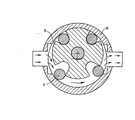
- In the enclosed schematic drawing, the Figure shows a cross section of the arrangement on which the referred system is based.
- As shown schematically in the Figure, the system of the present invention is basically formed by three units. The first unit (a) is stationary and consists of a cylindrical chamber having a closed top and bottom to be connected to the fluid line. The second rotatory unit (b)is a stationary unit and consists of a cylindrical rotor with grooves associated to a shaft which extends through the top and bottom of the first unit, its axis being parallel but not coincident with the axis of the first unit. The third unit (c) formed by a set of rolls which fit loosely into the grooves is of the same length as the two previous units. The position of fluid inlet and outlet is adequate for the use of the device as a hydraulic motor.
Claims (10)
characterized in that it comprises a first stationary unit consisting of a cylindrical chamber directly connected to the fluid line, a second rotary unit consisting of a cylindrical rotor having radial grooves associated to a shaft which extendss through the top and bottom of the first unit, its axis being parallel but not coincident with the axis of the first unit, a third unit formed by a set of rolls which loosely fit into the grooves and are as long as the length two above mentioned units so that the pressure of the fluid urges the rolls against the internal surface of the chamber, the walls of the grooves forming tight movable spaces, filled with fluid, the respective volumes being dependent upon the angular position of the rotor in relation to the chamber, the energy of " - the fluid being in this way transferred to the rotating shaft or, vice versa, from the rotating shaft to the fluid.
Applications Claiming Priority (2)
| Application Number | Priority Date | Filing Date | Title |
|---|---|---|---|
| PT82620 | 1986-05-20 | ||
| PT8262086A PT82620A (en) | 1986-05-20 | 1986-05-20 | Reversible system of energy transfer from a fluid to a mecanical axis in rotation |
Publications (2)
| Publication Number | Publication Date |
|---|---|
| EP0246567A2 true EP0246567A2 (en) | 1987-11-25 |
| EP0246567A3 EP0246567A3 (en) | 1988-03-30 |
Family
ID=20083836
Family Applications (1)
| Application Number | Title | Priority Date | Filing Date |
|---|---|---|---|
| EP87107033A Withdrawn EP0246567A3 (en) | 1986-05-20 | 1987-05-15 | Reversible system for the transfer of energy from a fluid to a rotating shaft |
Country Status (4)
| Country | Link |
|---|---|
| EP (1) | EP0246567A3 (en) |
| JP (1) | JPS6341671A (en) |
| DK (1) | DK254087A (en) |
| PT (1) | PT82620A (en) |
Family Cites Families (7)
| Publication number | Priority date | Publication date | Assignee | Title |
|---|---|---|---|---|
| GB220600A (en) * | 1923-08-14 | 1925-02-26 | Camille Lespinasse | Improvements in and relating to rotary pumps |
| FR844907A (en) * | 1938-10-18 | 1939-08-04 | L Outil R B V Sa | Rotary hydraulic pump, reversible as a motor |
| GB526730A (en) * | 1939-03-27 | 1940-09-24 | Edward Ewart Guinness | Improvements in or relating to rotary engines |
| GB540373A (en) * | 1940-04-08 | 1941-10-15 | Clifford Edmund Brewer | Improvements in rotary pumps and engines |
| GB577425A (en) * | 1943-11-03 | 1946-05-17 | Hickman Pneumatic Seat Company | Improvements in spring suspension for vehicles |
| GB577475A (en) * | 1944-04-29 | 1946-05-20 | Cyril Daniel Watson | Improvements in or relating to rotary motors, pumps and the like |
| LU45341A1 (en) * | 1963-02-05 | 1964-04-01 |
-
1986
- 1986-05-20 PT PT8262086A patent/PT82620A/en unknown
-
1987
- 1987-05-15 EP EP87107033A patent/EP0246567A3/en not_active Withdrawn
- 1987-05-19 DK DK254087A patent/DK254087A/en not_active Application Discontinuation
- 1987-05-20 JP JP12145287A patent/JPS6341671A/en active Pending
Also Published As
| Publication number | Publication date |
|---|---|
| PT82620A (en) | 1986-06-01 |
| EP0246567A3 (en) | 1988-03-30 |
| JPS6341671A (en) | 1988-02-22 |
| DK254087A (en) | 1987-11-21 |
| DK254087D0 (en) | 1987-05-19 |
Similar Documents
| Publication | Publication Date | Title |
|---|---|---|
| JP4121247B2 (en) | Non-lubricated screw rotor device | |
| Zimmern et al. | Design and operating characteristics of the zimmern single screw compressor | |
| US2716861A (en) | Pressure energy translating and like devices | |
| US5709188A (en) | Heat engine | |
| EP0747596A3 (en) | High displacement rate, scrolltype, fluid handling apparatus | |
| US1539728A (en) | Rotary pump | |
| US4028023A (en) | Fluid operable rotary piston device | |
| Badr et al. | Multi-vane expanders: internal-leakage losses | |
| US3221665A (en) | Hydraulic pump or motor with hydraulic pressure-responsive vane | |
| US6526937B1 (en) | Economical eccentric internal combustion engine | |
| US3797975A (en) | Rotor vane motor device | |
| Badr et al. | Performances of multi-vane expanders | |
| EP0246567A2 (en) | Reversible system for the transfer of energy from a fluid to a rotating shaft | |
| Bala et al. | Influence of organic working fluids on the performance of a positive-displacement pump with sliding vanes | |
| US4239466A (en) | Rotary machine with adjustable means for its eccentric rotor | |
| US20020068003A1 (en) | High speed UniVane fluid-handling device | |
| US3273502A (en) | Pumping and metering device | |
| US2368572A (en) | Rotary pump | |
| US4149835A (en) | Temperature responsive seal lubrication for rotary mechanisms | |
| JPS5564181A (en) | Scroll fluid machine | |
| US3963390A (en) | Bearing arrangement for rotary piston engine for compressing and expanding gases | |
| CA2150959C (en) | Cyclothermic converter vane pump and impeller system | |
| GB2098278A (en) | Rotary positive displacement fluid | |
| US4626181A (en) | Rotary hydrostatic machine with heated center housing port | |
| EP1056944B1 (en) | Heat engine |
Legal Events
| Date | Code | Title | Description |
|---|---|---|---|
| PUAI | Public reference made under article 153(3) epc to a published international application that has entered the european phase |
Free format text: ORIGINAL CODE: 0009012 |
|
| AK | Designated contracting states |
Kind code of ref document: A2 Designated state(s): AT BE CH DE ES FR GB GR IT LI LU NL SE |
|
| PUAL | Search report despatched |
Free format text: ORIGINAL CODE: 0009013 |
|
| AK | Designated contracting states |
Kind code of ref document: A3 Designated state(s): AT BE CH DE ES FR GB GR IT LI LU NL SE |
|
| 17P | Request for examination filed |
Effective date: 19880909 |
|
| 17Q | First examination report despatched |
Effective date: 19891012 |
|
| STAA | Information on the status of an ep patent application or granted ep patent |
Free format text: STATUS: THE APPLICATION IS DEEMED TO BE WITHDRAWN |
|
| 18D | Application deemed to be withdrawn |
Effective date: 19900223 |
|
| RIN1 | Information on inventor provided before grant (corrected) |
Inventor name: DOS REIS CARDOSO IGREJA, VIRGILIO |