EP0246484A2 - Screwed connection for the cylinder head of a combustion engine - Google Patents
Screwed connection for the cylinder head of a combustion engine Download PDFInfo
- Publication number
- EP0246484A2 EP0246484A2 EP87106449A EP87106449A EP0246484A2 EP 0246484 A2 EP0246484 A2 EP 0246484A2 EP 87106449 A EP87106449 A EP 87106449A EP 87106449 A EP87106449 A EP 87106449A EP 0246484 A2 EP0246484 A2 EP 0246484A2
- Authority
- EP
- European Patent Office
- Prior art keywords
- cylinder head
- threaded sleeve
- screw
- combustion engine
- cylinder
- Prior art date
- Legal status (The legal status is an assumption and is not a legal conclusion. Google has not performed a legal analysis and makes no representation as to the accuracy of the status listed.)
- Granted
Links
Images
Classifications
-
- F—MECHANICAL ENGINEERING; LIGHTING; HEATING; WEAPONS; BLASTING
- F16—ENGINEERING ELEMENTS AND UNITS; GENERAL MEASURES FOR PRODUCING AND MAINTAINING EFFECTIVE FUNCTIONING OF MACHINES OR INSTALLATIONS; THERMAL INSULATION IN GENERAL
- F16B—DEVICES FOR FASTENING OR SECURING CONSTRUCTIONAL ELEMENTS OR MACHINE PARTS TOGETHER, e.g. NAILS, BOLTS, CIRCLIPS, CLAMPS, CLIPS OR WEDGES; JOINTS OR JOINTING
- F16B5/00—Joining sheets or plates, e.g. panels, to one another or to strips or bars parallel to them
- F16B5/02—Joining sheets or plates, e.g. panels, to one another or to strips or bars parallel to them by means of fastening members using screw-thread
-
- F—MECHANICAL ENGINEERING; LIGHTING; HEATING; WEAPONS; BLASTING
- F02—COMBUSTION ENGINES; HOT-GAS OR COMBUSTION-PRODUCT ENGINE PLANTS
- F02F—CYLINDERS, PISTONS OR CASINGS, FOR COMBUSTION ENGINES; ARRANGEMENTS OF SEALINGS IN COMBUSTION ENGINES
- F02F1/00—Cylinders; Cylinder heads
-
- F—MECHANICAL ENGINEERING; LIGHTING; HEATING; WEAPONS; BLASTING
- F02—COMBUSTION ENGINES; HOT-GAS OR COMBUSTION-PRODUCT ENGINE PLANTS
- F02F—CYLINDERS, PISTONS OR CASINGS, FOR COMBUSTION ENGINES; ARRANGEMENTS OF SEALINGS IN COMBUSTION ENGINES
- F02F1/00—Cylinders; Cylinder heads
- F02F1/24—Cylinder heads
- F02F1/26—Cylinder heads having cooling means
- F02F1/36—Cylinder heads having cooling means for liquid cooling
- F02F1/38—Cylinder heads having cooling means for liquid cooling the cylinder heads being of overhead valve type
-
- F—MECHANICAL ENGINEERING; LIGHTING; HEATING; WEAPONS; BLASTING
- F16—ENGINEERING ELEMENTS AND UNITS; GENERAL MEASURES FOR PRODUCING AND MAINTAINING EFFECTIVE FUNCTIONING OF MACHINES OR INSTALLATIONS; THERMAL INSULATION IN GENERAL
- F16B—DEVICES FOR FASTENING OR SECURING CONSTRUCTIONAL ELEMENTS OR MACHINE PARTS TOGETHER, e.g. NAILS, BOLTS, CIRCLIPS, CLAMPS, CLIPS OR WEDGES; JOINTS OR JOINTING
- F16B43/00—Washers or equivalent devices; Other devices for supporting bolt-heads or nuts
-
- F—MECHANICAL ENGINEERING; LIGHTING; HEATING; WEAPONS; BLASTING
- F02—COMBUSTION ENGINES; HOT-GAS OR COMBUSTION-PRODUCT ENGINE PLANTS
- F02F—CYLINDERS, PISTONS OR CASINGS, FOR COMBUSTION ENGINES; ARRANGEMENTS OF SEALINGS IN COMBUSTION ENGINES
- F02F1/00—Cylinders; Cylinder heads
- F02F1/24—Cylinder heads
- F02F2001/244—Arrangement of valve stems in cylinder heads
- F02F2001/245—Arrangement of valve stems in cylinder heads the valve stems being orientated at an angle with the cylinder axis
-
- F—MECHANICAL ENGINEERING; LIGHTING; HEATING; WEAPONS; BLASTING
- F05—INDEXING SCHEMES RELATING TO ENGINES OR PUMPS IN VARIOUS SUBCLASSES OF CLASSES F01-F04
- F05C—INDEXING SCHEME RELATING TO MATERIALS, MATERIAL PROPERTIES OR MATERIAL CHARACTERISTICS FOR MACHINES, ENGINES OR PUMPS OTHER THAN NON-POSITIVE-DISPLACEMENT MACHINES OR ENGINES
- F05C2201/00—Metals
- F05C2201/02—Light metals
Definitions
- the invention relates to an internal combustion engine according to the preamble of claim 1.
- the cylinder head is attached to the cylinder crankcase either by hexagon screws or by studs screwed into the cylinder crankcase, the screw heads or the nuts abutting washers on a flat surface of the cylinder head.
- the dimensions of the washers must be selected so that the permissible surface pressure, which is approximately 150 N / mm2 in the case of the usual light metal alloys, is not exceeded.
- the outer diameter of the washer must be considerably larger than the outer diameter of the screw head or the nut.
- Such washers cannot be accommodated, particularly in the case of cylinder heads with more than two valves per cylinder, due to the limited space available.
- the invention has for its object to provide an internal combustion engine of the type specified in the preamble of claim 1, in which a sufficient contact surface for secure absorption of the screw forces is achieved by the light metal cylinder head even in extremely cramped conditions.
- the receiving area for the screw force is determined by the flanks of the thread of the threaded sleeve and, accordingly, a suitable area for receiving the screw force can be made available by appropriately selecting the number of thread turns in order to keep the surface pressure within the permissible limits without the space required for this being greater than the space required for the head or the nut of the cylinder head screw.
- the thread of the threaded sleeve preferably runs differently from the thread of the cylinder head screw, that is to say left-handed if the thread of the cylinder head screw is right-handed in the usual way. This prevents the threaded sleeve from being taken along when the cylinder head screw is tightened and additional screws being screwed in. Rather, the threaded sleeve is braced in the internal thread of the bore.
- This tensioning can be intensified if the outer end face of the threaded sleeve has the shape of a flat hollow cone and the cooperating end face of the head or the nut of the cylinder head screw has a complementary shape. This shape creates the threaded sleeve stretched and at the same time prevents deformation of the threaded sleeve in the direction of the screw shaft.
- a shoulder can be provided in the bore in the cylinder head, against which the threaded sleeve lies with its inner end face when screwed in.
- a disc made of a harder material than the material of the cylinder head can be placed on this shoulder in order to prevent deformation of this shoulder when the threaded sleeve is screwed in.
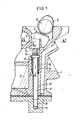
- Fig. 1 denotes a light metal cylinder head of an internal combustion engine and 2 denotes a cylinder crankcase.
- the cylinder head 1 has in the exemplary embodiment two intake valves and two exhaust valves for each cylinder, of which only one intake valve 3 is indicated that a tappet 4 which is actuated by a cam 5 of an overhead camshaft 6.
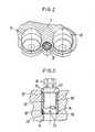
- Fig. 2 the holes 7 and 8 are shown for the tappets of the two inlet valves.
- the cylinder head 1 is screwed to the cylinder crankcase 2 by cylinder head screws 9, only one of which is shown.
- a bore 10 is provided in the cylinder head 1 and a threaded bore 11 in the cylinder crankcase.
- the screw 9 has a polygonal head 12 and a collar 13.
- the bore 10 in the cylinder head 1 is provided with a thread 14 into which a threaded sleeve 15 made of steel is screwed.
- the thread 14 and the cooperating external thread of the sleeve 15 have a different thread than the thread 16 of the screw 9 and the thread of the threaded bore 11 cooperating therewith. If the thread 16 is right-handed, as usual, the thread 14 is left-handed.
- the outer end face 17 of the threaded sleeve 15 forms the contact surface for the collar 13 of the cylinder head screw 9.
- the inner end face 18 of the threaded sleeve 15 lies against a shoulder 20, which is provided in the bore 10, via a washer 19.
- Recesses 21 at the lower end of the threaded sleeve 21 serve to engage a tool for screwing in the threaded sleeve 15.
- the receiving surface for the screw force is determined by the flanks of the thread of the threaded sleeve 15, and it can thus by appropriate choice of the number of threads A sufficient area for receiving the screw force can be created in order to keep the surface pressure within the permissible limits without the space required for this being greater than the space required for the collar 13 of the cylinder head screw 9. This can be clearly seen from FIG. 3.
- the outer end face 17 of the threaded sleeve 15 in the form of a flat hollow cone and the cooperating end face 22 of the collar 13 of the cylinder head screw 9 has a complementary shape.
- the threaded sleeve 15 is stretched at its outer end due to the interacting inclined surfaces 17 and 22.
- the threaded sleeve 15 can be secured against rotation in the usual way by a hardenable synthetic resin.
- the invention is not restricted to the exemplary embodiment shown.
- a stud screw with a nut can also be used, although such a nut generally takes up more space.
Landscapes
- Engineering & Computer Science (AREA)
- General Engineering & Computer Science (AREA)
- Mechanical Engineering (AREA)
- Chemical & Material Sciences (AREA)
- Combustion & Propulsion (AREA)
- Cylinder Crankcases Of Internal Combustion Engines (AREA)
- Connection Of Plates (AREA)
Abstract
Bei einer Brennkraftmaschine wird der Leichtmetall-Zylinderkopf 1 mit dem Zylinderkurbelgehäuse 2 durch Schrauben 9 verschraubt, die sich jeweils durch eine Bohrung 10 im Zylinderkopf 1 erstrecken und in eine Gewindebohrung 11 im Zylinderkurbelgehäuse 2 eingeschraubt sind. Um ohne die Verwendung von viel Platz beanspruchenden Beilagscheiben die Flächenpressung beim Anziehen der Zylinderkopfschraube auf ein für die Leichtmetallegierung des Zylinderkopfes 1 zulässige Größe zu halten, ist in die Bohrung 10 eine Gewindehülse 15 aus Stahl eingeschraubt, auf deren Stirnfläche 17 der Kopf der Zylinderkopfschraube 9 aufliegt. Die Aufnahmefläche für die Schraubenkraft wird dabei von den Flächen der Flanken des Gewindes der Gewindehülse 15 gebildet. Durch eine entsprechende Anzahl von Gewindegängen kann somit eine ausreichende Fläche der Verfügung gestellt werden, ohne daß der Außendurchmesser der Gewindehülse 15 größer sein muß als der Außendurchmesser des Schraubenkopfes 12, 13. 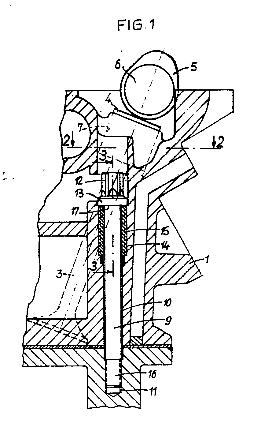
Description
Die Erfindung bezieht sich auf eine Brennkraftmaschine gemäß dem Oberbegriff des Anspruchs 1.The invention relates to an internal combustion engine according to the preamble of
Bei den bekannten Brennkraftmaschinen dieser Art erfolgt die Befestigung des Zylinderkopfes am Zylinderkurbelgehäuse entweder durch Sechskantschrauben oder durch in das Zylinderkurbelgehäuse eingeschraubte Stiftschrauben, wobei die Schraubenköpfe bzw. die Muttern über Beilagscheiben an einer Planfläche des Zylinderkopfes anliegen. Die Abmessungen der Beilagscheiben müssen dabei so gewählt werden, daß die zulässige Flächenpressung, die bei den üblichen Leichtmetallegierungen etwa 150 N/mm² beträgt, nicht überschritten wird. Dazu muß der Außendurchmesser der Beilagscheibe erheblich größer sein als der Außendurchmesser des Schraubenkopfes bzw. der Mutter. Derartige Beilagscheiben lassen sich jedoch insbesondere bei Zylinderköpfen mit mehr als zwei Ventilen pro Zylinder infolge der beengten Platzverhältnisse nicht unterbringen. Um hier Abhilfe zu schaffen, ist es bekannt, (DE-AS-27 33 445), die Beilagscheibe unsymmetrisch, beispielsweise in Form eines Kreisringes mit einer segmentartig abgeflachten Seite, auszubilden, und ein Drehen der Beilagscheibe beim Einschrauben der Zylinderkopfschraube bzw. beim Aufschrauben der Mutter durch eine Rippe zu verhindern, die an der Unterseite der Beilagscheibe vorgesehen ist und in das weichere Material des Zylinderkopfes eingedrückt wird. Damit kann jedoch nur eine Verschiebung der Auflagefläche erreicht werden, deren Größe durch die zulässige Flächenpressung bestimmt ist und unverändert bleibt. Diese große Auflagefläche ist jedoch in manchen Fällen nicht zu verwirklichen.In the known internal combustion engines of this type, the cylinder head is attached to the cylinder crankcase either by hexagon screws or by studs screwed into the cylinder crankcase, the screw heads or the nuts abutting washers on a flat surface of the cylinder head. The dimensions of the washers must be selected so that the permissible surface pressure, which is approximately 150 N / mm² in the case of the usual light metal alloys, is not exceeded. For this, the outer diameter of the washer must be considerably larger than the outer diameter of the screw head or the nut. Such washers, however, cannot be accommodated, particularly in the case of cylinder heads with more than two valves per cylinder, due to the limited space available. To remedy this, it is known (DE-AS-27 33 445) to design the washer asymmetrically, for example in the form of a circular ring with a segment-like flattened side, and to rotate the washer when screwing in the cylinder head screw or when screwing on to prevent the nut by a rib, which is provided on the underside of the washer and is pressed into the softer material of the cylinder head. However, this can only result in a shift of the contact surface, the size of which is determined by the permissible surface pressure and remains unchanged. In some cases, however, this large contact surface cannot be realized.
Der Erfindung liegt die Aufgabe zugrunde, eine Brennkraftmaschine der im Oberbegriff des Anspruchs 1 angegebenen Art zu schaffen, bei der auch bei außerdordentlich beengten Platzverhältnissen eine ausreichende Auflagefläche zur sicheren Aufnahme der Schraubenkräfte durch den Leichtmetall-Zylinderkopf erreicht wird.The invention has for its object to provide an internal combustion engine of the type specified in the preamble of
Diese Aufgabe wird erfindungsgemäß durch die im Kennzeichen des Anspruchs 1 angegebenen Merkmale gelöst.This object is achieved by the features specified in the characterizing part of
Bei dem erfindungsgemäßen Vorschlag wird die Aufnahmefläche für die Schraubenkraft von den Flanken des Gewindes der Gewindehülse bestimmt und es kann demzufolge durch entsprechende Wahl der Anzahl der Gewindegänge eine ausreichende Fläche zur Aufnahme der Schraubenkraft zur Verfügung gestellt werden, um die Flächenpressung in den zulässigen Grenzen zu halten, ohne daß der hierfür nötige Platz größer sein muß als der Platzbedarf für den Kopf bzw. die Mutter der Zylinderkopfschraube.In the proposal according to the invention, the receiving area for the screw force is determined by the flanks of the thread of the threaded sleeve and, accordingly, a suitable area for receiving the screw force can be made available by appropriately selecting the number of thread turns in order to keep the surface pressure within the permissible limits without the space required for this being greater than the space required for the head or the nut of the cylinder head screw.
Vorzugsweise ist das Gewinde der Gewindehülse andersgängig als das Gewinde der Zylinderkopfschraube, also linksgängig, wenn das Gewinde der Zylinderkopfschraube in üblicher Weise rechtsgängig ist. Dadurch wird verhindert, daß die Gewindehülse beim Festziehen der Zylinderkopfschraube mitgenommen und zusätzliche eingeschraubt wird. Vielmehr erfolgt ein Verspannen der Gewindehülse in dem Innengewinde der Bohrung. Dieses Verspannen kann noch verstärkt werden, wenn die äußere Stirnfläche der Gewindehülse die Form eines flachen Hohlkegels und die damit zusammenwirkende Stirnfläche des Kopfes bzw. der Mutter der Zylinderkopfschraube eine dazu komplementäre Form hat. Durch diese Formgebung wird die Gewindehülse gedehnt und gleichzeitig verhindert, daß eine Verformung der Gewindehülse in Richtung auf den Schraubenschaft erfolgt.The thread of the threaded sleeve preferably runs differently from the thread of the cylinder head screw, that is to say left-handed if the thread of the cylinder head screw is right-handed in the usual way. This prevents the threaded sleeve from being taken along when the cylinder head screw is tightened and additional screws being screwed in. Rather, the threaded sleeve is braced in the internal thread of the bore. This tensioning can be intensified if the outer end face of the threaded sleeve has the shape of a flat hollow cone and the cooperating end face of the head or the nut of the cylinder head screw has a complementary shape. This shape creates the threaded sleeve stretched and at the same time prevents deformation of the threaded sleeve in the direction of the screw shaft.
Schließlich kann in der Bohrung im Zylinderkopf eine Schulter vorgesehen werden, an der die Gewindehülse mit ihrer inneren Stirnfläche im eingeschraubten Zustand anliegt. Auf diese Schulter kann eine Scheibe aus einem härteren Material als dem Material des Zylinderkopfes aufgelegt werden, um eine Verformung dieser Schulter beim Einschrauben der Gewindehülse zu verhindern.Finally, a shoulder can be provided in the bore in the cylinder head, against which the threaded sleeve lies with its inner end face when screwed in. A disc made of a harder material than the material of the cylinder head can be placed on this shoulder in order to prevent deformation of this shoulder when the threaded sleeve is screwed in.
Ein Ausführungsbeispiel der Erfindung wird im folgenden unter Bezugnahme auf die Zeichnungen beschrieben. Es zeigt:
- Fig. 1 einen Teilschnitt eines Zylinderkopfes und des benachbarten Bereiches eines Zylinderkurbelgehäuses,
- Fig. 2 einen Schnitt des Zylinderkopfes entlang Linie 2-2 in Fig. 1, und
- Fig. 3 einen Teilschnitt entlang Linie 3-3 in Fig. 1 in größerem Maßstab,
- 1 is a partial section of a cylinder head and the adjacent area of a cylinder crankcase,
- Fig. 2 shows a section of the cylinder head along line 2-2 in Fig. 1, and
- 3 is a partial section along line 3-3 in Fig. 1 on a larger scale,
In Fig. 1 ist mit 1 ein Leichtmetall-Zylinderkopf einer Brennkraftmaschine und mit 2 ein Zylinderkurbelgehäuse bezeichnet. Der Zylinderkopf 1 weist im Ausführungsbeispiel für jeden Zylinder zwei Einlaßventile und zwei Auslaßventile auf, von denen nur ein Einlaßventil 3 angedeutet ist, daß einen Tassenstößel 4 aufweist, der von einem Nocken 5 einer obenliegenen Nockenwelle 6 betätigt wird. In Fig. 2 sind die Bohrungen 7 und 8 für die Tassenstößel der beiden Einlaßventile dargestellt.In Fig. 1, 1 denotes a light metal cylinder head of an internal combustion engine and 2 denotes a cylinder crankcase. The
Der Zylinderkopf 1 ist mit dem Zylinderkurbelgehäuse 2 durch Zylinderkopfschrauben 9 verschraubt, von denen lediglich eine dargestellt ist. Zur Aufnahme jener Schraube 9 ist im Zylinderkopf 1 eine Bohrung 10 und im Zylinderkurbelgehäuse eine Gewindebohrung 11 vorgesehen. Die Schraube 9 weist einen Mehrkant-Kopf 12 und einen Bund 13 auf. Die Bohrung 10 im Zylinderkopf 1 ist mit einem Gewinde 14 versehen, in das eine Gewindehülse 15 aus Stahl eingeschraubt ist. Das Gewinde 14 und das damit zusammenwirkende Außengewinde der Hülse 15 sind andersgängig als das Gewinde 16 der Schraube 9 und das damit zusammenwirkende Gewinde der Gewindebohrung 11. Ist das Gewinde 16, wie üblich, rechtsgängig, so ist das Gewinde 14 linksgängig. Die äußere Stirnfläche 17 der Gewindehülse 15 bildet die Auflagefläche für den Bund 13 der Zylinderkopfschraube 9. Die innere Stirnfläche 18 der Gewindehülse 15 liegt über eine Beilagscheibe 19 an einer Schulter 20 an, die in der Bohrung 10 vorgesehen ist. Aussparungen 21 am unteren Ende der Gewindehülse 21 dienen zum Angriff eines Werkzeuges zum Einschrauben der Gewindehülse 15.The
Wie aus Fig. 2 ersichtlich ist, ist zwischen den Bohrungen 7 und 8 für benachbarte Tassenstößel nur sehr wenig Platz für die Unterbringung einer Zylinderkopfschraube vorhanden, der keinesfalls ausreicht, um zwischen dem Kopf der Zylinderkopfschraube bzw. bei Verwendung einer Stiftschraube zwischen der Mutter und der Auflagefläche am Zylinderkopf eine Beilagscheibe solcher Größe vorzusehen, daß die zulässige Flächenpressung beim Anziehen der Schraube oder Mutter nicht überschritten wird. Bei dem dargestellten Ausführungsbeispiel wird die Aufnahmefläche für die Schraubenkraft von den Flanken des Gewindes der Gewindehülse 15 bestimmt, und es kann somit durch entsprechende Wahl der Anzahl der Gewindegänge eine ausreichende Fläche zur Aufnahme der Schraubenkraft geschaffen werden, um die Flächenpressung in den zulässigen Grenzen zu halten, ohne daß der hierfür nötige Platz größer sein muß als der Platzbedarf für den Bund 13 der Zylinderkopfschraube 9. Dies ist deutlich aus Fig. 3 ersichtlich.As can be seen from Fig. 2, there is very little space between the
Dadurch, daß das Gewinde der Gewindehülse 15 andersgängig ist als das Gewinde der Zylinderkopfschraube 9, wird vermieden, daß die Gewindehülse 15 beim Festziehen der Zylinderkopfschraube 9 mitgenommen und zusätzlich eingeschraubt wird. Vielmehr findet ein Verspannen der Gewindegänge der Gewindehülse 15 mit den Gewindegängen des Innengewindes 14 statt, wodurch aufgrund des relativ weichen Materials des Zylinderkopfes 1 erreicht wird, daß alle Gewindegänge tragen und somit eine große Aufnahmefläche für die Schraubenkraft erreicht wird. Dieses Verspannen kann noch verstärkt werden, indem, wie aus Fig. 3 ersichtlich, die äußere Stirnfläche 17 der Gewindehülse 15 die Form eines flachen Hohlkegels und die damit zusammenwirkende Stirnfläche 22 des Bundes 13 der Zylinderkopfschraube 9 eine dazu komplementäre Form hat. Beim Anziehen der Zylinderkopfschraube 9 wird aufgrund der miteinander zusammenwirkenden Schrägflächen 17 und 22 ein Dehnen der Gewindehülse 15 an ihrem äußeren Ende erreicht. Zusätzlich kann die Gewindehülse 15 in üblicher Weise durch ein aushärtbares Kunstharz gegen Verdrehung gesichert werden.Characterized in that the thread of the threaded
Die Erfindung ist nicht auf das dargestellt Ausführungsbeispiel beschränkt. So kann anstelle der dargestellten Schraube 9 mit einem Mehrkant-Kopf 12 und einem Bund 13 auch eine Stiftschraube mit Mutter verwendet werden, obgleich eine derartige Mutter im allgemeinen mehr Raum beansprucht.The invention is not restricted to the exemplary embodiment shown. Thus, instead of the
Claims (6)
dadurch gekennzeichnet,
daß die Bohrung (10) im Zylinderkopf (1) ein Gewinde aufweist, in das eine Gewindehülse (15) aus einem härteren Material als der Zylinderkopf eingeschraubt ist, deren äußere Stirnfläche (17) die Auflagefläche für den Kopf (12) oder die Mutter der Zylinderkopfschraube (9) bildet.1. Internal combustion engine with a cylinder crankcase (2) and a light metal cylinder head (1) which is connected to the cylinder crankcase by screws (9), each of which extends through a bore (19) in the cylinder head and into a threaded bore (11) in Cylinder crankcase are screwed in and their heads (12) or nuts interact positively with the cylinder head,
characterized,
that the bore (10) in the cylinder head (1) has a thread into which a threaded sleeve (15) made of a harder material is screwed than the cylinder head, the outer end face (17) of which is the contact surface for the head (12) or the nut of the Forms the cylinder head screw (9).
Applications Claiming Priority (2)
| Application Number | Priority Date | Filing Date | Title |
|---|---|---|---|
| DE3616629 | 1986-05-16 | ||
| DE19863616629 DE3616629A1 (en) | 1986-05-16 | 1986-05-16 | INTERNAL COMBUSTION ENGINE |
Publications (3)
| Publication Number | Publication Date |
|---|---|
| EP0246484A2 true EP0246484A2 (en) | 1987-11-25 |
| EP0246484A3 EP0246484A3 (en) | 1988-07-27 |
| EP0246484B1 EP0246484B1 (en) | 1990-08-16 |
Family
ID=6301022
Family Applications (1)
| Application Number | Title | Priority Date | Filing Date |
|---|---|---|---|
| EP87106449A Expired - Lifetime EP0246484B1 (en) | 1986-05-16 | 1987-05-05 | Screwed connection for the cylinder head of a combustion engine |
Country Status (4)
| Country | Link |
|---|---|
| US (1) | US5069176A (en) |
| EP (1) | EP0246484B1 (en) |
| JP (1) | JPH089977B2 (en) |
| DE (2) | DE3616629A1 (en) |
Cited By (1)
| Publication number | Priority date | Publication date | Assignee | Title |
|---|---|---|---|---|
| DE102007057343A1 (en) | 2007-11-28 | 2009-06-04 | Bayerische Motoren Werke Aktiengesellschaft | Light metal crankcase for an internal-combustion engine, comprises a cast threaded bush made of a material having larger elastic module than the crankcase, and a hollow positioning arm axially or radially arranged to the bush |
Families Citing this family (13)
| Publication number | Priority date | Publication date | Assignee | Title |
|---|---|---|---|---|
| JP3089689B2 (en) * | 1991-03-20 | 2000-09-18 | スズキ株式会社 | Cylinder head oil passage structure |
| US5630389A (en) * | 1995-09-29 | 1997-05-20 | Self; Kevin G. | Cylinder head bolt plug |
| DE19737492C1 (en) * | 1997-08-28 | 1998-10-29 | Daimler Benz Ag | Liquid cooled cylinder head for motor vehicle internal combustion engine |
| US6109232A (en) * | 1998-10-05 | 2000-08-29 | Bomar; Scott L. | Locating implement for engine head |
| DE19847478B4 (en) * | 1998-10-15 | 2007-09-13 | Audi Ag | Cast component made of light metal |
| DE10029242B4 (en) * | 2000-06-14 | 2013-01-03 | GM Global Technology Operations LLC (n. d. Ges. d. Staates Delaware) | Cylinder head attachment to a cylinder block of an internal combustion engine |
| DE102004001908A1 (en) * | 2004-01-14 | 2005-08-04 | Daimlerchrysler Ag | Cylinder head for a liquid-cooled internal combustion engine with gas change channels, cooling agent space around the channels and bracing elements in the cylinder head made of stronger material than the material surrounding the head |
| DE202005005872U1 (en) * | 2005-04-13 | 2005-06-16 | Textron Verbindungstechnik Gmbh & Co. Ohg | Steel sleeve for aluminium cylinder head bolt has an external self tapping thread to secure accurately into the head |
| FR2956443A1 (en) * | 2010-02-12 | 2011-08-19 | Peugeot Citroen Automobiles Sa | Cylinder head for internal combustion engine of vehicle i.e. motor vehicle, has set of housings receiving each support disk, where form of head permits disc to free support pads to reach housing without risk of blocking |
| JP2011185367A (en) * | 2010-03-09 | 2011-09-22 | Nabtesco Corp | Member connecting structure and gear device |
| CN103016496B (en) * | 2012-12-19 | 2015-02-11 | 中联重科股份有限公司 | Threaded connection structure, pin puller and boom |
| DE102013114318B4 (en) * | 2013-12-18 | 2016-09-22 | Steyr Motors Gmbh | Multi-part crankcase and assembly process |
| CN106089474B (en) * | 2016-06-13 | 2018-10-12 | 宁波市鄞州德来特技术有限公司 | A kind of cylinder of gasoline engine and the assembly method for installing cylinder head |
Family Cites Families (12)
| Publication number | Priority date | Publication date | Assignee | Title |
|---|---|---|---|---|
| FR617048A (en) * | 1926-06-03 | 1927-02-12 | New engine cylinder head | |
| FR636678A (en) * | 1926-10-23 | 1928-04-14 | Method of shell or sand casting a two or more part internal combustion engine cylinder head | |
| FR795981A (en) * | 1935-01-04 | 1936-03-26 | Improvements to light alloy cylinder heads | |
| FR1078588A (en) * | 1952-04-02 | 1954-11-19 | Bayerische Motoren Werke Ag | Screw fixing of removable light metal cylinder heads of internal combustion engines fitted with rocker valves |
| DE1767628U (en) * | 1954-12-24 | 1958-05-29 | Zuendapp Werke G M B H | FOR COMBUSTION ENGINES, IN PARTICULAR TWO-STROKE ENGINES AS SMALL POWER MACHINES, CERTAIN CYLINDERS. |
| DE1113335B (en) * | 1959-11-26 | 1961-08-31 | Daimler Benz Ag | Screw connection between a component and a connecting element made of materials with different modulus of elasticity |
| US3103921A (en) * | 1960-08-11 | 1963-09-17 | Motoren Werke Mannheim Ag | Cylinder head arrangements for internal combustion engines |
| DE1294095B (en) * | 1963-03-20 | 1969-04-30 | Porsche Kg | Internal combustion engine, in particular air-cooled internal combustion engine |
| DE2365413A1 (en) * | 1973-03-24 | 1974-11-28 | Steyr Daimler Puch Ag | SUPPORT CONSTRUCTION FOR EXTERNAL CYLINDER HEAD SCREWS OF PISTON MACHINES |
| FR2528511A1 (en) * | 1982-06-14 | 1983-12-16 | Peugeot | BEARING CAP FOR CAMSHAFT AT HEAD OF INTERNAL COMBUSTION ENGINE, AND CORRESPONDING ENGINE |
| US4745892A (en) * | 1985-06-28 | 1988-05-24 | Audi Ag | Internal combustion engine |
| DE3541700A1 (en) * | 1985-11-26 | 1987-05-27 | Audi Ag | INTERNAL COMBUSTION ENGINE WITH AT LEAST ONE OVERHEAD CAMSHAFT |
-
1986
- 1986-05-16 DE DE19863616629 patent/DE3616629A1/en not_active Withdrawn
-
1987
- 1987-05-05 EP EP87106449A patent/EP0246484B1/en not_active Expired - Lifetime
- 1987-05-05 DE DE8787106449T patent/DE3764306D1/en not_active Expired - Lifetime
- 1987-05-15 JP JP62119972A patent/JPH089977B2/en not_active Expired - Fee Related
-
1989
- 1989-11-13 US US07/436,099 patent/US5069176A/en not_active Expired - Lifetime
Cited By (2)
| Publication number | Priority date | Publication date | Assignee | Title |
|---|---|---|---|---|
| DE102007057343A1 (en) | 2007-11-28 | 2009-06-04 | Bayerische Motoren Werke Aktiengesellschaft | Light metal crankcase for an internal-combustion engine, comprises a cast threaded bush made of a material having larger elastic module than the crankcase, and a hollow positioning arm axially or radially arranged to the bush |
| DE102007057343B4 (en) | 2007-11-28 | 2019-02-07 | Bayerische Motoren Werke Aktiengesellschaft | Light metal component for an internal combustion engine |
Also Published As
| Publication number | Publication date |
|---|---|
| US5069176A (en) | 1991-12-03 |
| EP0246484A3 (en) | 1988-07-27 |
| DE3764306D1 (en) | 1990-09-20 |
| JPS639660A (en) | 1988-01-16 |
| JPH089977B2 (en) | 1996-01-31 |
| EP0246484B1 (en) | 1990-08-16 |
| DE3616629A1 (en) | 1987-11-19 |
Similar Documents
| Publication | Publication Date | Title |
|---|---|---|
| DE69522439T2 (en) | BLIND FASTENER WITH DEFORMABLE SLEEVE | |
| DE3990293C2 (en) | ||
| EP0246484B1 (en) | Screwed connection for the cylinder head of a combustion engine | |
| DE60313869T2 (en) | BLIND-FIXED AND DRIVING NUT AND METHOD FOR THE APPLICATION THEREOF | |
| EP3032093B1 (en) | Fastening device for fastening a rotor blade to a rotor hub of a wind energy plant | |
| DE4006028C2 (en) | Connecting bolts and arrangement of components | |
| DE3624938C2 (en) | Loss protection arrangement on ignition coils for motor vehicles | |
| DE102004051424B4 (en) | Device for adjusting the camshaft of an internal combustion engine and assembly tool | |
| DE60200173T2 (en) | System for fastening a component to a support part | |
| DE3923131A1 (en) | FASTENING ELEMENT, ESPECIALLY FOR A BALL SCREW | |
| DE29809229U1 (en) | bolt | |
| EP0228533B1 (en) | Internal-combustion engine with at least one overhead camshaft | |
| DE69201645T2 (en) | BRAKE PISTON ADJUSTMENT MECHANISM. | |
| DE1816880A1 (en) | Fixing device with automatic limitation of the applied torque | |
| DE3410872C2 (en) | ||
| DE2463427C2 (en) | ||
| DE3620090C2 (en) | ||
| DE3329104A1 (en) | FASTENING ELEMENT AND METHOD FOR ATTACHING THE SAME | |
| DE2139869A1 (en) | Fastener | |
| DE19746877B4 (en) | Device for adjusting the valve clearance on the cylinder head of an internal combustion engine | |
| EP1881211A2 (en) | Mounting device consisting of screw and sleeve | |
| DE102020116616A1 (en) | screw | |
| DE2736131A1 (en) | Locking screw with short plain shank - having frusto=conical section immediately under grooved head and expanding towards it | |
| DE19905706C2 (en) | Combination nut with inclined washer | |
| DE327999C (en) | Nut lock |
Legal Events
| Date | Code | Title | Description |
|---|---|---|---|
| PUAI | Public reference made under article 153(3) epc to a published international application that has entered the european phase |
Free format text: ORIGINAL CODE: 0009012 |
|
| AK | Designated contracting states |
Kind code of ref document: A2 Designated state(s): DE FR GB IT |
|
| PUAL | Search report despatched |
Free format text: ORIGINAL CODE: 0009013 |
|
| AK | Designated contracting states |
Kind code of ref document: A3 Designated state(s): DE FR GB IT |
|
| 17P | Request for examination filed |
Effective date: 19880813 |
|
| 17Q | First examination report despatched |
Effective date: 19890106 |
|
| GRAA | (expected) grant |
Free format text: ORIGINAL CODE: 0009210 |
|
| AK | Designated contracting states |
Kind code of ref document: B1 Designated state(s): DE FR GB IT |
|
| REF | Corresponds to: |
Ref document number: 3764306 Country of ref document: DE Date of ref document: 19900920 |
|
| ITF | It: translation for a ep patent filed | ||
| GBT | Gb: translation of ep patent filed (gb section 77(6)(a)/1977) | ||
| ET | Fr: translation filed | ||
| ITTA | It: last paid annual fee | ||
| PLBE | No opposition filed within time limit |
Free format text: ORIGINAL CODE: 0009261 |
|
| STAA | Information on the status of an ep patent application or granted ep patent |
Free format text: STATUS: NO OPPOSITION FILED WITHIN TIME LIMIT |
|
| 26N | No opposition filed | ||
| REG | Reference to a national code |
Ref country code: GB Ref legal event code: IF02 |
|
| PG25 | Lapsed in a contracting state [announced via postgrant information from national office to epo] |
Ref country code: IT Free format text: LAPSE BECAUSE OF NON-PAYMENT OF DUE FEES;WARNING: LAPSES OF ITALIAN PATENTS WITH EFFECTIVE DATE BEFORE 2007 MAY HAVE OCCURRED AT ANY TIME BEFORE 2007. THE CORRECT EFFECTIVE DATE MAY BE DIFFERENT FROM THE ONE RECORDED. Effective date: 20050505 |
|
| PGFP | Annual fee paid to national office [announced via postgrant information from national office to epo] |
Ref country code: GB Payment date: 20060424 Year of fee payment: 20 |
|
| PGFP | Annual fee paid to national office [announced via postgrant information from national office to epo] |
Ref country code: FR Payment date: 20060518 Year of fee payment: 20 |
|
| PGFP | Annual fee paid to national office [announced via postgrant information from national office to epo] |
Ref country code: DE Payment date: 20060531 Year of fee payment: 20 |
|
| REG | Reference to a national code |
Ref country code: GB Ref legal event code: PE20 |
|
| PG25 | Lapsed in a contracting state [announced via postgrant information from national office to epo] |
Ref country code: GB Free format text: LAPSE BECAUSE OF EXPIRATION OF PROTECTION Effective date: 20070504 |