EP0246482A2 - Vane pump - Google Patents
Vane pump Download PDFInfo
- Publication number
- EP0246482A2 EP0246482A2 EP87106419A EP87106419A EP0246482A2 EP 0246482 A2 EP0246482 A2 EP 0246482A2 EP 87106419 A EP87106419 A EP 87106419A EP 87106419 A EP87106419 A EP 87106419A EP 0246482 A2 EP0246482 A2 EP 0246482A2
- Authority
- EP
- European Patent Office
- Prior art keywords
- end plate
- cam ring
- center axis
- housing
- rear end
- Prior art date
- Legal status (The legal status is an assumption and is not a legal conclusion. Google has not performed a legal analysis and makes no representation as to the accuracy of the status listed.)
- Granted
Links
Images


Classifications
-
- F—MECHANICAL ENGINEERING; LIGHTING; HEATING; WEAPONS; BLASTING
- F01—MACHINES OR ENGINES IN GENERAL; ENGINE PLANTS IN GENERAL; STEAM ENGINES
- F01C—ROTARY-PISTON OR OSCILLATING-PISTON MACHINES OR ENGINES
- F01C21/00—Component parts, details or accessories not provided for in groups F01C1/00 - F01C20/00
- F01C21/10—Outer members for co-operation with rotary pistons; Casings
-
- F—MECHANICAL ENGINEERING; LIGHTING; HEATING; WEAPONS; BLASTING
- F04—POSITIVE - DISPLACEMENT MACHINES FOR LIQUIDS; PUMPS FOR LIQUIDS OR ELASTIC FLUIDS
- F04C—ROTARY-PISTON, OR OSCILLATING-PISTON, POSITIVE-DISPLACEMENT MACHINES FOR LIQUIDS; ROTARY-PISTON, OR OSCILLATING-PISTON, POSITIVE-DISPLACEMENT PUMPS
- F04C15/00—Component parts, details or accessories of machines, pumps or pumping installations, not provided for in groups F04C2/00 - F04C14/00
-
- F—MECHANICAL ENGINEERING; LIGHTING; HEATING; WEAPONS; BLASTING
- F04—POSITIVE - DISPLACEMENT MACHINES FOR LIQUIDS; PUMPS FOR LIQUIDS OR ELASTIC FLUIDS
- F04C—ROTARY-PISTON, OR OSCILLATING-PISTON, POSITIVE-DISPLACEMENT MACHINES FOR LIQUIDS; ROTARY-PISTON, OR OSCILLATING-PISTON, POSITIVE-DISPLACEMENT PUMPS
- F04C2230/00—Manufacture
- F04C2230/60—Assembly methods
- F04C2230/603—Centering; Aligning
-
- Y—GENERAL TAGGING OF NEW TECHNOLOGICAL DEVELOPMENTS; GENERAL TAGGING OF CROSS-SECTIONAL TECHNOLOGIES SPANNING OVER SEVERAL SECTIONS OF THE IPC; TECHNICAL SUBJECTS COVERED BY FORMER USPC CROSS-REFERENCE ART COLLECTIONS [XRACs] AND DIGESTS
- Y10—TECHNICAL SUBJECTS COVERED BY FORMER USPC
- Y10T—TECHNICAL SUBJECTS COVERED BY FORMER US CLASSIFICATION
- Y10T29/00—Metal working
- Y10T29/49—Method of mechanical manufacture
- Y10T29/49229—Prime mover or fluid pump making
- Y10T29/49236—Fluid pump or compressor making
- Y10T29/49245—Vane type or other rotary, e.g., fan
Definitions
- the present invention relates in general to a vane pump and in particular to a vane pump which is used in a power steering of an internal combustion engine.
- a conventional vane pump as shown in FIGS. 5 and 6 of the accompanying drawings is disclosed in the US-A- 4,373,871.
- reference numeral 1 designates a housing formed with a housing bore 2.
- a drive shaft 4 through a bearing 3 secured to the housing 1.
- a pump portion generally indicated by reference numeral 5 is housed in the housing bore 2 of the housing 1 and includes a cam ring 6 having a cam surface 6a consisting of a large circular portion and a small circular portion, a rotor 7 freely rotatably supported in the cam ring 6 and having a plurality of equiangularly spaced slots formed therein, a plurality of vanes 8 radially movably received in the slots of the rotor 7, and front and rear plates 9 and 10 by which the cam ring 6 is closed at its opposite ends.
- the drive shaft 4 extends through a central opening formed in the front plate 9 and through a central opening formed in the rotor 7, and the rotor 7 is engaged with the drive shaft 4 through a spline formed in the drive shaft 4 between the front and rear plate 9 and 10.
- a rear end portion of the drive shaft 4 extending rearward from the rotor 7 is freely rotatably supported on a bearing portion 11 formed in the the rear plate 10 through a bearing 12.
- the front plate 9, cam ring 6 and rear plate 10 are held together in assembled relationship by means of a pair of knock pins 14.
- Each of the knock pins 14 is inserted into a bore 13 formed in the inner surface of the housing 1, a bore 15 passing through the front plate 9, a bore 16 passing through the cam ring 6 and into a bore 17 formed in the rear plate 10 so that the center axis of the rotor 7 is consistent with the center axis of the cam surface 6a of the cam ring 6.
- the vane pump is to be operated in this offset condition because the slight offset between the center axes 6b and 7a cannot be inspected visually.
- the rotor 7 is rotated in the counter-clockwise direction indicated by an arrow B in FIG.
- the vane 8b of two adjacent vanes 8a and 8b which are located at the section between an intake port 6c and a discharge port 6d and which define a pump chamber 18, is slightly lengthened in its length from the outer surface of the rotor 7 to the cam surface 6a than the vane 8b in the condition that the center axis 7a of the rotor 7 is not offset. For this reason, the pump chamber 18 is slightly increased in its volume at the side of the vane 8b.
- the vane 8d of two adjacent vanes 8c and 8d which are located at the section between the intake port 6c and the discharge port 6d and which define a pump chamber 19 opposite to the chamber 18, is slightly shortened in its length from the outer surface of the rotor 7 to the cam surface 6a than the vane 8d in the condition that the center axis 7a of the rotor 7 is not offset. For this reason, the pump chamber 19 is slightly decreased in its volume at the side of the vane 8d.
- the bore 13 of the housing 1, the bore 15 of the front plate 9, the bore 16 of the cam ring 6 and the bore 17 of the rear plate 10 must be cut accurately so that they are axially aligned with one another.
- the conventional vane pump therefore, has the disadvantages that it necessitates a plurality of cutting operation and is expensive to manufacture.
- a vane pump comprising a housing formed with a cam ring housing portion; a drive shaft freely rotatably supported in the housing; a rotor inserted on the drive shaft and engaged with the drive shaft, the rotor having a center axis passing therethrough; a cam ring having the rotor freely rotatably accommodated therein and having a cam surface having a center axis passing therethrough; and a front end plate by which the cam ring is closed at its one end; a rear end plate formed with a bearing portion through which one end portion of the drive shaft is freely rotatably supported, the rear end plate having mounted therein at least a pair of knock pins each of which is spaced at a predetermined distance from a center axis of the bearing portion of the rear end plate; the center axis of the rotor and the center axi
- the cam ring may be formed at its outer peripheral wall with recess portions of substantially semicircular configuration in cross section, the recess portions being engaged with the knock pins mounted in the rear end plate so that the center axis of the rotor and the center axis of the cam surface are aligned with each other.
- the housing may be formed at its inner peripheral wall with recess portions of substantially semicircular configuration in cross section
- the front end plate may be formed at its outer peripheral wall with recess portions of substantially semicircular configuration in cross section
- the semicircular bore of the housing and the semicircular bore of the front end plate constituting a circular bore in combination with the recess portion of the cam ring
- the front end plate, cam ring and rear end plate being attached to the housing by inserting the knock pin mounted in the rear end plate in the circular bore.
- the cam ring is engaged with the knock pins through the recess portions formed in the cam ring, and the one end portion of the drive shaft is inserted in the bearing portion formed in the rear end plate.
- the center axis of the rotor is aligned with the center axis of the cam surface of the cam ring.
- the rotor does not oscillate within the cam surface, thereby preventing the occurrence of noise caused by the oscillation.
- FIGS. 1 to 4 of the drawings are views showing one embodiment of a vane pump constructed in accordance with the present invention and used in a power steering apparatus of an automotive vehicle
- a pump housing is designated by reference numeral 21 and formed with a cam ring housing portion.
- the pump housing 21 has a drive shaft 24 freely rotatably supported therein through a front bearing 23 secured to the front boss portion of the housing 21.
- the drive shaft 24 is driven to rotate about its own axis by an engine (not shown) of the automotive vehicle.
- a cam ring 26 having a cam surface 26a consisting of a large circular portion and a small circular portion, a rotor 27 freely rotatably supported within the cam surface 26a of the cam ring 26, and a front end plate 28 by which the cam ring 26 is closed at the one end thereof.
- a rear end plate 30 closing the other end of the cam ring 26 is provided to hermetically seal the pump housing 21 as a rear cover.
- the rear end plate 30 is formed at the central portion thereof with a bearing bore 32 in which a rear end portion 24a of the drive shaft 24 extending through the front end plate 28 and'rotor 27 is freely rotatably supported through a rear bearing 31 secured to the rear end plate 30.
- the rear end plate 30 is formed with a pair of knock pin bores 33 and 33 each of which is spaced a predetermined distance from the center axis of the bearing bore 32 and which are disposed symmetrically with respect to the center axis of the bearing bore 32.
- a knock pin 34 In each of the knock pin bores 33 and 33 is press fitted a knock pin 34.
- the cam ring 26 is formed at the outer peripheral wall thereof with a pair of recess portions 35 and 35 of substantially semicircular configuration in cross section.
- the cam ring 26 is to be attached to the rear end plate 30 and the center axis of the cam surface 26a of the cam ring 26 is to be axially aligned with the center axis of the bearing bore 32 of the rear end plate 30.
- an inner peripheral wall of the cam ring housing portion 21a of the housing 21 and an outer peripheral wall of the front end plate 28 are formed with recess portions 36 and 37 of semicircular configuration in cross section, respectively.
- the semicircular recess portion 35 in formed in the outer peripheral wall of the cam ring 26, the semicircular recess portion 36 formed in'the inner peripheral wall of the housing 21 and the semicircular recess portion 37 formed in the outer peripheral wall of the front end plate 28 as a whole constitute an alignment bore designated generally by reference numeral 38.
- the front end plate 28, cam ring 26 and rear end plate 30 are attached to the pump housing 21 by inserting the knock pin 34 press fitted in the rear end plate 30 in the alignment bore 38.
- the recess portion 35 may be replaced with an axial bore formed in the cam ring 26, the center axis of the axial bore being parallel to the center axis of the cam ring 26.
- the front end plate 28 and rotor 27 are inserted on the drive shaft 24 accommodated in the housing 21, and the rotor 27 is mounted on the drive shaft 24 through the spline formed in the drive shaft 24.
- the cam ring 26 is engaged with the knock pins 34 press fitted in the rear end plate 30 through the semicircular recess portion 35 formed in the cam ring 26, and is attached to the rear end plate 30.
- the center axis of bearing bore 32 in the rear end plate 30 and the center axis of the cam surface 26a are aligned with each other.
- the knock pins 34 are inserted in the alignment bores 38 constituted by the semicircular bores 35, 36 and 37 so that the cam ring 26 is accommodated in the cam ring housing portion 21a of the housing 21, and also the rear end portion 24a of the drive shaft 24 is inserted in the--bearing bore 32 of the rear end portion 30 through the bearing 31. Since the drive shaft 24 is passed through the centeral portion of the rotor 27, the center axis of the cam surface 26a and the center axis of the rotor 27 are aligned with each other.
- the center axis of the cam surface of the cam ring and the center axis of the rotor are capable of being aligned with each other only by engaging the cam ring with the knock pins mounted in the rear end plate. Accordingly, other accurate cutting operation is not necessary, thereby reducing the cost of production.
- the center axis of the cam surface of the cam ring and the center axis of the rotor are not offset from each other in assembling, the oscillation and noise does not occur during operation of the vane pump according to the present invention.
Landscapes
- Engineering & Computer Science (AREA)
- Mechanical Engineering (AREA)
- General Engineering & Computer Science (AREA)
- Rotary Pumps (AREA)
Abstract
Description
- The present invention relates in general to a vane pump and in particular to a vane pump which is used in a power steering of an internal combustion engine. A conventional vane pump as shown in FIGS. 5 and 6 of the accompanying drawings is disclosed in the US-A- 4,373,871. In FIG. 5,
reference numeral 1 designates a housing formed with ahousing bore 2. In thehousing bore 2 is freely rotatably supported adrive shaft 4 through a bearing 3 secured to thehousing 1. A pump portion generally indicated byreference numeral 5 is housed in thehousing bore 2 of thehousing 1 and includes acam ring 6 having acam surface 6a consisting of a large circular portion and a small circular portion, arotor 7 freely rotatably supported in thecam ring 6 and having a plurality of equiangularly spaced slots formed therein, a plurality of vanes 8 radially movably received in the slots of therotor 7, and front andrear plates 9 and 10 by which thecam ring 6 is closed at its opposite ends. Thedrive shaft 4 extends through a central opening formed in the front plate 9 and through a central opening formed in therotor 7, and therotor 7 is engaged with thedrive shaft 4 through a spline formed in thedrive shaft 4 between the front andrear plate 9 and 10. A rear end portion of thedrive shaft 4 extending rearward from therotor 7 is freely rotatably supported on a bearing portion 11 formed in the therear plate 10 through a bearing 12. The front plate 9,cam ring 6 andrear plate 10 are held together in assembled relationship by means of a pair ofknock pins 14. Each of theknock pins 14 is inserted into abore 13 formed in the inner surface of thehousing 1, abore 15 passing through the front plate 9, abore 16 passing through thecam ring 6 and into a bore 17 formed in therear plate 10 so that the center axis of therotor 7 is consistent with the center axis of thecam surface 6a of thecam ring 6. - However, in such a conventional vane pump, in order that the center axis of the
rotor 7 is consistent with the center axis of thecam surface 6a of thecam ring 6, the center axes of thebores bores rotor 7 is slightly offset from the center axis 6b of thecam surface 6a. If thepump portion 5 is assembled with the center axis 7b of the rotor slightly offset from the center axis of 6b of thecam surface 6a, the vane pump is to be operated in this offset condition because the slight offset between the center axes 6b and 7a cannot be inspected visually. In this case, for instance, if therotor 7 is rotated in the counter-clockwise direction indicated by an arrow B in FIG. 6 with the condition that the center axis 7b of therotor 7 is offset slightly from the center axis 6b of thecam surface 6a, thevane 8b of twoadjacent vanes intake port 6c and adischarge port 6d and which define apump chamber 18, is slightly lengthened in its length from the outer surface of therotor 7 to thecam surface 6a than thevane 8b in the condition that the center axis 7a of therotor 7 is not offset. For this reason, thepump chamber 18 is slightly increased in its volume at the side of thevane 8b. On the other hand, thevane 8d of twoadjacent vanes intake port 6c and thedischarge port 6d and which define a pump chamber 19 opposite to thechamber 18, is slightly shortened in its length from the outer surface of therotor 7 to thecam surface 6a than thevane 8d in the condition that the center axis 7a of therotor 7 is not offset. For this reason, the pump chamber 19 is slightly decreased in its volume at the side of thevane 8d. Consequently, the fluid pressure in the pump chamber 19 becomes momentarily higher than the fluid pressure in thepump chamber 18 during rotation of therotor 7, and therefore therotor 7 is subjected to a force caused by the differential pressure between thechambers 18 and 19 in the direction indicated by an arrow A in FIG. 6. There is, on the other hand, a play between thedrive shaft 4, and thehousing 1 andrear plate 10 because therotor 7 is splined to thedrive shaft 4 and because thedrive shaft 4 is supported on thehousing 1 andrear plate 10 through the bearings 3 and 12. Consequently, when therotor 7 is subjected to the force in the direction A, thedrive shaft 4 oscillates together with therotor 7, and therefore the oscillation and noise occur in the conventional vane pump. In order to avoid the occurrence of the oscillation and noise, thebore 13 of thehousing 1, thebore 15 of the front plate 9, thebore 16 of thecam ring 6 and the bore 17 of therear plate 10 must be cut accurately so that they are axially aligned with one another. The conventional vane pump, therefore, has the disadvantages that it necessitates a plurality of cutting operation and is expensive to manufacture. - It is, accordingly, an important object of the present invention to provide an improved vane pump which can eliminates and prevents the drawbacks in the prior art. The object of the present invention is achieved by a vane pump comprising a housing formed with a cam ring housing portion; a drive shaft freely rotatably supported in the housing; a rotor inserted on the drive shaft and engaged with the drive shaft, the rotor having a center axis passing therethrough; a cam ring having the rotor freely rotatably accommodated therein and having a cam surface having a center axis passing therethrough; and a front end plate by which the cam ring is closed at its one end; a rear end plate formed with a bearing portion through which one end portion of the drive shaft is freely rotatably supported, the rear end plate having mounted therein at least a pair of knock pins each of which is spaced at a predetermined distance from a center axis of the bearing portion of the rear end plate; the center axis of the rotor and the center axis of the cam surface being aligned with each other and being accommodated in the cam ring housing portion of the housing by engaging the cam ring with the pair of knock pins of the rear end plate and attaching the cam ring to the rear end plate. The cam ring may be formed at its outer peripheral wall with recess portions of substantially semicircular configuration in cross section, the recess portions being engaged with the knock pins mounted in the rear end plate so that the center axis of the rotor and the center axis of the cam surface are aligned with each other. The housing may be formed at its inner peripheral wall with recess portions of substantially semicircular configuration in cross section, and the front end plate may be formed at its outer peripheral wall with recess portions of substantially semicircular configuration in cross section, the semicircular bore of the housing and the semicircular bore of the front end plate constituting a circular bore in combination with the recess portion of the cam ring, the front end plate, cam ring and rear end plate being attached to the housing by inserting the knock pin mounted in the rear end plate in the circular bore. In accordance with the present invention, the cam ring is engaged with the knock pins through the recess portions formed in the cam ring, and the one end portion of the drive shaft is inserted in the bearing portion formed in the rear end plate. As a result, the center axis of the rotor is aligned with the center axis of the cam surface of the cam ring. Thus, since the center axes of the rotor and the cam surface of the cam ring is aligned with each other, the rotor does not oscillate within the cam surface, thereby preventing the occurrence of noise caused by the oscillation. In addition, in order to align the center axis of the rotor with the center axis of the cam surface, it is only required that the cam ring is engaged with the knock pins mounted in the rear end plate. Accordingly, other accurate cutting operation is not necessary.
- The drawbacks of a conventional vane pump and the features and advantages of a vane pump according to the present invention will be more clearly understood from the following description taken in conjunction with the accompanying drawings in which like reference numerals designate corresponding or similar members and structures throughout the figures of the drawings and in which:
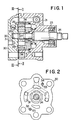
- FIG. 1 is a cross sectional view showing one embodiment of a vane pump constructed in accordance with the present invention;
- FIG. 2 is a cross sectional view substantially taken along line II-II indicated in FIG. 1;
- FIG. 3 is a cross sectional view substantially taken along line III-III indicated in FIG. 1;
- FIG. 4 is a cross sectional view of a knock pin by which a center axis of a rotor is aligned with a center axis of a cam ring;
- FIG. 5 is a cross sectional view showning the conventional vane pump; and
- FIG. 6 is a cross sectional view substantially taken along line VI-VI indicated in FIG. 5.
- Referring to FIGS. 1 to 4 of the drawings, which are views showing one embodiment of a vane pump constructed in accordance with the present invention and used in a power steering apparatus of an automotive vehicle, a pump housing is designated by
reference numeral 21 and formed with a cam ring housing portion. Thepump housing 21 has adrive shaft 24 freely rotatably supported therein through a front bearing 23 secured to the front boss portion of thehousing 21. Thedrive shaft 24 is driven to rotate about its own axis by an engine (not shown) of the automotive vehicle. In the cam ring housing portion of thehousing 21 are accommodated acam ring 26 having acam surface 26a consisting of a large circular portion and a small circular portion, a rotor 27 freely rotatably supported within thecam surface 26a of thecam ring 26, and a front end plate 28 by which thecam ring 26 is closed at the one end thereof. Arear end plate 30 closing the other end of thecam ring 26 is provided to hermetically seal thepump housing 21 as a rear cover. Therear end plate 30 is formed at the central portion thereof with abearing bore 32 in which arear end portion 24a of thedrive shaft 24 extending through the front end plate 28 and'rotor 27 is freely rotatably supported through arear bearing 31 secured to therear end plate 30. Thus, since thedrive shaft 24 is supported in the bearing bore 32 through thebearing 31, the center axes of thebearing bore 32 and the rotor 27 are aligned with each other. As shown in FIG. 2, therear end plate 30 is formed with a pair ofknock pin bores bearing bore 32 and which are disposed symmetrically with respect to the center axis of thebearing bore 32. In each of theknock pin bores knock pin 34. On the other hand, as clearly shown in FIG. 3, thecam ring 26 is formed at the outer peripheral wall thereof with a pair ofrecess portions knock pins knock pin bores rear end plate 30 are engaged with thesemicircular recess portions cam ring 26, respectively, thecam ring 26 is to be attached to therear end plate 30 and the center axis of thecam surface 26a of thecam ring 26 is to be axially aligned with the center axis of thebearing bore 32 of therear end plate 30. In addition, as clearly shown in FIG. 4, an inner peripheral wall of the cam ring housing portion 21a of thehousing 21 and an outer peripheral wall of the front end plate 28 are formed withrecess portions semicircular recess portion 35 in formed in the outer peripheral wall of thecam ring 26, thesemicircular recess portion 36 formed in'the inner peripheral wall of thehousing 21 and thesemicircular recess portion 37 formed in the outer peripheral wall of the front end plate 28 as a whole constitute an alignment bore designated generally byreference numeral 38. The front end plate 28,cam ring 26 andrear end plate 30 are attached to thepump housing 21 by inserting theknock pin 34 press fitted in therear end plate 30 in thealignment bore 38. It is noted that therecess portion 35 may be replaced with an axial bore formed in thecam ring 26, the center axis of the axial bore being parallel to the center axis of thecam ring 26. - The operation of the vane pump thus constructed in accordance with the present invention will hereinafter be described in detail.
- The front end plate 28 and rotor 27 are inserted on the
drive shaft 24 accommodated in thehousing 21, and the rotor 27 is mounted on thedrive shaft 24 through the spline formed in thedrive shaft 24. On the other hand, thecam ring 26 is engaged with theknock pins 34 press fitted in therear end plate 30 through thesemicircular recess portion 35 formed in thecam ring 26, and is attached to therear end plate 30. As thecam ring 26 is attached to therear end plate 30, the center axis ofbearing bore 32 in therear end plate 30 and the center axis of thecam surface 26a are aligned with each other. Theknock pins 34 are inserted in thealignment bores 38 constituted by thesemicircular bores cam ring 26 is accommodated in the cam ring housing portion 21a of thehousing 21, and also therear end portion 24a of thedrive shaft 24 is inserted in the--bearing bore 32 of therear end portion 30 through thebearing 31. Since thedrive shaft 24 is passed through the centeral portion of the rotor 27, the center axis of thecam surface 26a and the center axis of the rotor 27 are aligned with each other. - Thus, in order to align the center axis of the
cam surface 26a with the center axis of the rotor 27, thecam ring 26 is dependent upon theknock pin 34. Consequently, only thesemicircular recess portion 35 of thecam ring 26 engaged by theknock pin 34 is required to be cut accurately, and thus the accuracy is easily obtainable as compared with the aforementioned prior art. - In addition, even if the
semicircular recess portion 36 formed in thehousing 21, thesemicircular recess portion 37 formed in the front end plate 28 and the inner surface of thehousing 21 were cut roughly, there would be no problem because the center axis of thecam surface 26a and the center axis of the rotor 27 is aligned only by theknock pin 34. As a result, it is not necessary to cut accuracy therecess portions - Furthermore, in accommodating the
cam ring 26 attached to therear end plation 30 in the cam ring housing portion of thehousing 21 and inserting theread end portion 24a of thedrive shaft 24 in thebearing bore 32 formed in therear end plate 30, since thecam ring 26 depends upon only theknock pins 34, the center axis of thecam surface 26a and the center axis of the rotor 27 is not offset from each other. - . Hence, when the vane pump thus assembled is operated, the rotor 27 rotates in the direction indicated by an arrow C in FIG. 3, and a pump chamber 40 defined by two
adjacent vanes intake port 26b and adischarge port 26c is substantially equal in volume to apump chamber 41 defined by twoadjacent vanes 29c and 29d which are located in the section between theintake port 26b and thedischarge port 26c. Therefore, a differential pressure does not occur between the working oil in thepump chambers 40 and 41. For this reason, the rotor 27 is not subjected to a force caused by the differential pressure, and thus the oscillation and noise of the vane pump is considerably reduced. - From the foregoing description, it will be seen that an improved vane pump which can prevent the oscillation and noise and which can reduce the cost of production is afforded by the present design. That is, the center axis of the cam surface of the cam ring and the center axis of the rotor are capable of being aligned with each other only by engaging the cam ring with the knock pins mounted in the rear end plate. Accordingly, other accurate cutting operation is not necessary, thereby reducing the cost of production. In addition, since the the center axis of the cam surface of the cam ring and the center axis of the rotor are not offset from each other in assembling, the oscillation and noise does not occur during operation of the vane pump according to the present invention.
Claims (3)
Applications Claiming Priority (2)
| Application Number | Priority Date | Filing Date | Title |
|---|---|---|---|
| JP61117066A JP2670770B2 (en) | 1986-05-20 | 1986-05-20 | Vane pump |
| JP117066/86 | 1986-05-20 |
Publications (3)
| Publication Number | Publication Date |
|---|---|
| EP0246482A2 true EP0246482A2 (en) | 1987-11-25 |
| EP0246482A3 EP0246482A3 (en) | 1988-09-21 |
| EP0246482B1 EP0246482B1 (en) | 1991-02-27 |
Family
ID=14702578
Family Applications (1)
| Application Number | Title | Priority Date | Filing Date |
|---|---|---|---|
| EP87106419A Expired - Lifetime EP0246482B1 (en) | 1986-05-20 | 1987-05-04 | Vane pump |
Country Status (5)
| Country | Link |
|---|---|
| US (1) | US4842500A (en) |
| EP (1) | EP0246482B1 (en) |
| JP (1) | JP2670770B2 (en) |
| KR (1) | KR950000261B1 (en) |
| DE (1) | DE3768140D1 (en) |
Cited By (1)
| Publication number | Priority date | Publication date | Assignee | Title |
|---|---|---|---|---|
| FR2635831A1 (en) * | 1988-08-30 | 1990-03-02 | Aisin Seiki | HYDRAULIC PUMP SYSTEM FOR HYDRAULICALLY DRIVEN FAN SYSTEM |
Families Citing this family (13)
| Publication number | Priority date | Publication date | Assignee | Title |
|---|---|---|---|---|
| JPH02101088U (en) * | 1989-01-30 | 1990-08-10 | ||
| JPH0373689U (en) * | 1989-11-24 | 1991-07-24 | ||
| JP2963519B2 (en) * | 1990-10-11 | 1999-10-18 | 豊田工機株式会社 | Vane pump |
| US5267840A (en) * | 1991-09-03 | 1993-12-07 | Deco-Grand, Inc. | Power steering pump with balanced porting |
| US5290155A (en) * | 1991-09-03 | 1994-03-01 | Deco-Grand, Inc. | Power steering pump with balanced porting |
| DE4313282C2 (en) * | 1993-04-23 | 1998-05-20 | Balzers Pfeiffer Gmbh | Method of manufacturing a pump system |
| JP3710227B2 (en) * | 1995-12-06 | 2005-10-26 | カヤバ工業株式会社 | Vane pump |
| JP4471805B2 (en) * | 2004-10-06 | 2010-06-02 | カヤバ工業株式会社 | Vane pump |
| JP2007162554A (en) * | 2005-12-13 | 2007-06-28 | Kayaba Ind Co Ltd | Vane pump |
| JP5786642B2 (en) * | 2011-10-26 | 2015-09-30 | トヨタ自動車株式会社 | Stator fixing structure |
| CN102606476B (en) * | 2012-04-05 | 2015-01-14 | 王汉国 | Method for improving working stability of vane type hydraulic oil pump |
| JP6218653B2 (en) * | 2014-03-13 | 2017-10-25 | Kyb株式会社 | Vane pump and manufacturing method thereof |
| JP6581450B2 (en) * | 2015-09-16 | 2019-09-25 | Kyb株式会社 | Vane pump |
Citations (4)
| Publication number | Priority date | Publication date | Assignee | Title |
|---|---|---|---|---|
| FR2061059A5 (en) * | 1969-09-05 | 1971-06-18 | Eaton Yale & Towne | |
| GB2016599A (en) * | 1978-03-03 | 1979-09-26 | Trw Inc | Rotary positive-displacement fluid-machines |
| EP0048322A1 (en) * | 1980-09-20 | 1982-03-31 | Robert Bosch Gmbh | Gear machine with centering means for the cover plates |
| US4573890A (en) * | 1984-10-22 | 1986-03-04 | Atsugi Motor Parts Co., Ltd. | Vane pump with locating pins for cam ring |
Family Cites Families (4)
| Publication number | Priority date | Publication date | Assignee | Title |
|---|---|---|---|---|
| US2733687A (en) * | 1956-02-07 | schmid | ||
| US3289601A (en) * | 1965-02-12 | 1966-12-06 | Fawick Corp | Fluid displacement device usable as a hydraulic motor or pump |
| US4201521A (en) * | 1978-03-20 | 1980-05-06 | Trw Inc. | Pump and motor assembly |
| JPS5536839A (en) * | 1978-09-07 | 1980-03-14 | Kawaguchiko Seimitsu Kk | Display device in finder in single-lens reflex camera |
-
1986
- 1986-05-20 JP JP61117066A patent/JP2670770B2/en not_active Expired - Lifetime
-
1987
- 1987-04-20 KR KR1019870003783A patent/KR950000261B1/en not_active IP Right Cessation
- 1987-05-04 EP EP87106419A patent/EP0246482B1/en not_active Expired - Lifetime
- 1987-05-04 DE DE8787106419T patent/DE3768140D1/en not_active Expired - Lifetime
-
1988
- 1988-08-09 US US07/230,701 patent/US4842500A/en not_active Expired - Lifetime
Patent Citations (4)
| Publication number | Priority date | Publication date | Assignee | Title |
|---|---|---|---|---|
| FR2061059A5 (en) * | 1969-09-05 | 1971-06-18 | Eaton Yale & Towne | |
| GB2016599A (en) * | 1978-03-03 | 1979-09-26 | Trw Inc | Rotary positive-displacement fluid-machines |
| EP0048322A1 (en) * | 1980-09-20 | 1982-03-31 | Robert Bosch Gmbh | Gear machine with centering means for the cover plates |
| US4573890A (en) * | 1984-10-22 | 1986-03-04 | Atsugi Motor Parts Co., Ltd. | Vane pump with locating pins for cam ring |
Cited By (3)
| Publication number | Priority date | Publication date | Assignee | Title |
|---|---|---|---|---|
| FR2635831A1 (en) * | 1988-08-30 | 1990-03-02 | Aisin Seiki | HYDRAULIC PUMP SYSTEM FOR HYDRAULICALLY DRIVEN FAN SYSTEM |
| DE3928029A1 (en) * | 1988-08-30 | 1990-03-22 | Aisin Seiki | HYDRAULIC PUMP FOR A HYDRAULICALLY OPERATED FAN SYSTEM |
| DE3928029C2 (en) * | 1988-08-30 | 1993-07-29 | Aisin Seiki K.K., Kariya, Aichi, Jp |
Also Published As
| Publication number | Publication date |
|---|---|
| JPS62271982A (en) | 1987-11-26 |
| EP0246482B1 (en) | 1991-02-27 |
| EP0246482A3 (en) | 1988-09-21 |
| DE3768140D1 (en) | 1991-04-04 |
| US4842500A (en) | 1989-06-27 |
| JP2670770B2 (en) | 1997-10-29 |
| KR950000261B1 (en) | 1995-01-12 |
| KR870011380A (en) | 1987-12-23 |
Similar Documents
| Publication | Publication Date | Title |
|---|---|---|
| EP0246482A2 (en) | Vane pump | |
| JPS6126638Y2 (en) | ||
| EP0399387A2 (en) | Rotary vane machine | |
| KR960015461B1 (en) | Fuel pump for motor vehicle | |
| EP0049881B1 (en) | Scroll type fluid displacement apparatus with compression modifying means | |
| RU98114833A (en) | TWO CYLINDER VANE PUMP | |
| US4443168A (en) | Gear machine centering arrangement | |
| US4909714A (en) | Pressure balanced external gear pump or motor of floating shaft type | |
| KR960008056A (en) | Bearing plate and outlet of supercharger and improved housing teeth | |
| US5554019A (en) | Compact gerotor pump | |
| GB2118247A (en) | Rotary positive-displacement pump | |
| GB2160928A (en) | Pressure balancing in rotary positive-displacement machines | |
| EP0095194A1 (en) | Rotary vane pump | |
| JP4215160B2 (en) | Internal gear pump and manufacturing method thereof | |
| US5876194A (en) | Fixed-displacement vane-type hydraulic machine | |
| JPH10331777A (en) | Internal gear pump | |
| EP0881390B2 (en) | Oil pump apparatus | |
| JPH0633776B2 (en) | Gear pump | |
| JP2000145658A (en) | Internal gear pump | |
| KR970005854B1 (en) | Gerotor pump | |
| JP2540545Y2 (en) | Liquid pump | |
| KR930006371B1 (en) | Internal gear pump | |
| JPH0893656A (en) | Gear pump or motor | |
| JP3718869B2 (en) | Eccentric vacuum pump | |
| WO2022219886A1 (en) | Pump device |
Legal Events
| Date | Code | Title | Description |
|---|---|---|---|
| PUAI | Public reference made under article 153(3) epc to a published international application that has entered the european phase |
Free format text: ORIGINAL CODE: 0009012 |
|
| AK | Designated contracting states |
Kind code of ref document: A2 Designated state(s): DE FR GB |
|
| PUAL | Search report despatched |
Free format text: ORIGINAL CODE: 0009013 |
|
| AK | Designated contracting states |
Kind code of ref document: A3 Designated state(s): DE FR GB |
|
| 17P | Request for examination filed |
Effective date: 19881220 |
|
| 17Q | First examination report despatched |
Effective date: 19890612 |
|
| GRAA | (expected) grant |
Free format text: ORIGINAL CODE: 0009210 |
|
| AK | Designated contracting states |
Kind code of ref document: B1 Designated state(s): DE FR GB |
|
| REF | Corresponds to: |
Ref document number: 3768140 Country of ref document: DE Date of ref document: 19910404 |
|
| ET | Fr: translation filed | ||
| PLBE | No opposition filed within time limit |
Free format text: ORIGINAL CODE: 0009261 |
|
| STAA | Information on the status of an ep patent application or granted ep patent |
Free format text: STATUS: NO OPPOSITION FILED WITHIN TIME LIMIT |
|
| 26N | No opposition filed | ||
| REG | Reference to a national code |
Ref country code: GB Ref legal event code: IF02 |
|
| REG | Reference to a national code |
Ref country code: GB Ref legal event code: 732E |
|
| REG | Reference to a national code |
Ref country code: FR Ref legal event code: TP Ref country code: FR Ref legal event code: CD |
|
| PGFP | Annual fee paid to national office [announced via postgrant information from national office to epo] |
Ref country code: DE Payment date: 20060427 Year of fee payment: 20 |
|
| PGFP | Annual fee paid to national office [announced via postgrant information from national office to epo] |
Ref country code: GB Payment date: 20060503 Year of fee payment: 20 |
|
| PGFP | Annual fee paid to national office [announced via postgrant information from national office to epo] |
Ref country code: FR Payment date: 20060515 Year of fee payment: 20 |
|
| REG | Reference to a national code |
Ref country code: GB Ref legal event code: PE20 |
|
| PG25 | Lapsed in a contracting state [announced via postgrant information from national office to epo] |
Ref country code: GB Free format text: LAPSE BECAUSE OF EXPIRATION OF PROTECTION Effective date: 20070503 |