EP0246440A2 - Conveying device for pasty products - Google Patents
Conveying device for pasty products Download PDFInfo
- Publication number
- EP0246440A2 EP0246440A2 EP87105174A EP87105174A EP0246440A2 EP 0246440 A2 EP0246440 A2 EP 0246440A2 EP 87105174 A EP87105174 A EP 87105174A EP 87105174 A EP87105174 A EP 87105174A EP 0246440 A2 EP0246440 A2 EP 0246440A2
- Authority
- EP
- European Patent Office
- Prior art keywords
- zone
- displacement
- run
- rotor
- pistons
- Prior art date
- Legal status (The legal status is an assumption and is not a legal conclusion. Google has not performed a legal analysis and makes no representation as to the accuracy of the status listed.)
- Withdrawn
Links
Images

Classifications
-
- A—HUMAN NECESSITIES
- A22—BUTCHERING; MEAT TREATMENT; PROCESSING POULTRY OR FISH
- A22C—PROCESSING MEAT, POULTRY, OR FISH
- A22C11/00—Sausage making ; Apparatus for handling or conveying sausage products during manufacture
- A22C11/02—Sausage filling or stuffing machines
- A22C11/08—Sausage filling or stuffing machines with pressing-worm or other rotary-mounted pressing-members
Definitions
- the invention relates to a device for dispensing portions of a paste-like mass, with the same weight and / or volume, in particular sausage meat, with a conveyor consisting of a driven rotor mounted in a housing with a feed and a discharge opening with portion chambers in which displacement pistons are supported are arranged displaceably with respect to a stationary control cam, this comprising a section controlling the ejection movement of the displacement pistons, so that there is proportionality between the mass output and the angle of rotation of the rotor over a full rotation of the rotor.
- the device on which the subject of the invention is based is known from DE-OS 34 09 517.
- the conveyor for paste-like masses disclosed there has the features of a radial piston pump, in which the radial displacement movement of the displacement pistons takes place by means of a stationary control cam, on which the displacement pistons are supported during the rotation of the rotor receiving the same.
- the arrangement of the displacement pistons is coordinated with the position of the discharge opening of the housing and the assignment of the portion of the control curve which is responsible for the portioning stroke of the displacement pistons so that the ejection movement of one of them begins at the moment when the preceding one is his Ejection movement has ended.
- the portion of the control cam which controls the ejection movement of the displacement pistons comprises a run-up zone, an involute section and a run-off zone, the run-up zone and the run-off zone being designed in such a way that the respective sum of the dimensions between the support points of which are in each case Areas of the displacement piston supporting the control curve and the contact radii to be considered for the axis follow a linear function dependent on the angle of rotation _y of the rotor.
- a preferred embodiment is realized in a radial piston conveyor, in which the rotor mounted in the housing of the conveyor is provided with at least six radially arranged portion chambers with displaceable pistons slidably guided therein, and the control curve is arranged to support the lower surfaces of the displacer pistons facing the axis of the rotor.
- the housing 2 of a conveyor 1 is equipped with a feed 3 and a discharge opening 4 approximately opposite this.
- the housing 2 encloses a radially and axially self-sealingly fitted rotor 5, which is driven in a suitable manner around an axis 6.
- the rotor 5 has, with its central axes, centrally extending bores which intersect at an angle of 60 ° and form portion chambers 7, which serve to accommodate displacer pistons 8.1 to 8.6 fitted with a slight sliding fit.
- Each two opposing displacement pistons are connected in a suitable manner detachably by means of connecting webs 9 to form units that are bridge-like a control cam 11, which is located in a central recess 10 of the rotor 5, overlaps on the periphery of the control cam 11 with the support of the respective lower surfaces 12 of the displacement pistons 8.1 to 8.6.
- This comprises a compression section 14, which emerges from a concentric section 13 and, counterclockwise, comprises a start-up zone, an involute section and a discharge zone, which in turn merges into a concentric section 15.
- the feed opening 3 and the discharge opening 4 lie opposite one another, their peripheral expansions comprising a central angle with respect to the axis 6 with an angular dimension which corresponds essentially to that of the central angle, which includes the compression section 14, so that two successive portion chambers 7 each with the Delivery opening 4 or feed opening 3 are connected.
- the displacement piston 8.4 is tracked, which initially corresponds to the stroke line HS.4 in the pre-compression section 16 under moderate acceleration a ' 8.4 by a defined amount of stroke while pre-compressing the filling material located in the associated portion chamber 7 radially outwards against what is closed in this area Housing 2 is raised.
- the lifting position reached at the end of the penultimate section 16 is maintained over the rest of the section 13 comprising the pre-compression section 16 after the lifting speed has been reduced with a moderate deceleration -a ' 8.4 .
- the displacement piston 8.4 now passes through the compression section 14 of the control cam 11, over which area the portion chamber 7 is connected to the dispensing opening 4, and begins with moderate acceleration a 8.4 during the overflow of the starting zone 14.1 with the discharge of the filling material from the portion chamber 7 the leading displacement piston 8.3 is reduced in its stroke speed by overflowing the discharge zone 14.3 with a deceleration -a 8.3 symmetrical to the acceleration a 8.4 , and this is brought to zero towards the end of the compression section 14, which Maximum coincides.
- the displacer piston 8.4 has reached the involute section 14.2, which gives the former the uniform lifting speed v 8 . 4 granted, ie its acceleration drops to zero.
- the following passage through the discharge zone 14.3 causes a deceleration -a 8.4 of the stroke speed, during which the subsequent displacement piston 8.5 is symmetrical with respect to its stroke speed to that of the displacement piston 8.4 of an acceleration a 8 . 5 is subjected to the fact that it simultaneously passes through the startup zone 14.1.
- Each displacement piston is subjected to this movement profile with respect to its leading one with a phase shift of 6 0 °, so that during the effectiveness of the start zone 14.1 and discharge zone 14.3, two displacement pistons are involved in the mass ejection, while the involute section 14.2 only has to actuate one of them.
- the described conveyor can be used to derive a signal proportional to the output volume with the aid of an angle of rotation feedback. It is therefore possible with this device to produce the same portions by successively traversing the same angle of rotation.
- the stepper motor is the most suitable for this type of drive.
Landscapes
- Life Sciences & Earth Sciences (AREA)
- Engineering & Computer Science (AREA)
- Wood Science & Technology (AREA)
- Zoology (AREA)
- Food Science & Technology (AREA)
- Processing Of Meat And Fish (AREA)
- Reciprocating Pumps (AREA)
- Applications Or Details Of Rotary Compressors (AREA)
Abstract
Die Erfindung betrifft eine Vorrichtung zum Fördern pastenartiger Massen, beispielsweise Wurstbrät. Ausgehend von einem Radialkolbenförderer für eine drehwinkelproportionale Abgabe von Portionen, die durch Ausbildung des den Masseausstoß steuernden Abschnittes der Steuerkurve als Kreisevolvente ermöglicht wird, wird vorgeschlagen, die bei dieser Ausführung an jedem Verdrängerkolben im Augenblick des Beginns seiner Förderung wirksamen hohen, theoretisch unendlich hohen Beschleunigungskräfte dadurch abzubauen, daß der Evolventenabschnitt der Steuerkurve eine Anlaufund eine Ablaufzone erhält, deren Verläufe spiegelbildlich zueinander ausgestaltet sind. Dabei ist deren Anordnung so getroffen, daß im Augenblick des Auflaufes eines Verdrängerkolbens auf diese Auflaufzone der vorauslaufende in die genannte Ablaufzone eintritt, so daß während des Durchlaufens dieser Kurventeile jeweils zwei Verdrängerkolben an dem Masseausstoß beteiligt sind. Die Beschleunigungswerte derselben addieren sich dabei zu Null.
Description
Die Erfindung betrifft eine Vorrichtung zum Ausbringen gewichts- und/oder volumengleicher Portionen einer pastenartigen Masse, insbeondere Wurstbrät, mit einem Förderwerk, bestehend aus einem angetriebenen, in einem Gehäuse mit einer Zuführ- und einer Abgabeöffnung gelagerten Rotor mit Portionskammern, in denen Verdrängerkolben durch Abstützung gegenüber einer stationären Steuerkurve verschiebbar angeordnet sind, wobei diese einen die Ausstoßbewegung der--Verdrängerkolben steuernden Abschnitt umfaßt, so daß sich über einer Volldrehung des Rotors jeweils Proportionalität zwischen Masseausstoß und Drehwinkel des Rotors ergibt.The invention relates to a device for dispensing portions of a paste-like mass, with the same weight and / or volume, in particular sausage meat, with a conveyor consisting of a driven rotor mounted in a housing with a feed and a discharge opening with portion chambers in which displacement pistons are supported are arranged displaceably with respect to a stationary control cam, this comprising a section controlling the ejection movement of the displacement pistons, so that there is proportionality between the mass output and the angle of rotation of the rotor over a full rotation of the rotor.
Die dem Erfindungsbetreff zugrundeliegende Vorrichtung ist aus der DE-OS 34 09 517 bekannt. Das dort offenbarte Förderwerk für pastenartige Massen weist die Merkmale einer Radialkolbenpumpe auf, bei welcher die radiale Verschiebebewegung der Verdrängerkolben durch eine ortsfeste Steuerkurve erfolgt, auf welcher sich die Verdrängerkolben während des Umlaufs des dieselben aufnehmenden Rotors abstützen. Dabei ist die Anordnung der Verdrängerkolben in Abstimmung mit der Lage der Abgabeöffnung des'Gehäuses sowie die Zuordnung des Abschnittes der Steuerkurve, der für den Portionierhub der Verdrängerkolben verantwortlich ist, so getroffen, daß die Ausstoßbewegung eines derselben in dem Augenblick beginnt, wenn der vorauslaufende seine Ausstoßbewegung beendet hat. Im Hinblick auf das gesteckte Ziel, Proportionalität zwischen Fördervolumen und Drehwinkel des Rotors zu erreichen, ergeben sich sowohl für den Beginn der Ausstoßbewegung eines Verdrängerkolbens, als auch für das Ende der Äpsstoßbewegung des vorauslaufenden theoretisch unendlich hohe Beschleunigungswerte an den letztgenannten. Aufgrund der Elastizität des Systems werden diese Werte praktisch natürlich nicht erreicht, doch sind diese derartig hoch, daß das bekannte Förderwerk sehr rauh läuft, was unangenehme Geräuschentwicklung und überdurchschnittlichen Verschleiß zur Folge hat. Darüberhinaus bewirken die in der Praxis sich einstellenden Abweichungen des Bewegungsablaufes von der theoretischen Vorgabe Schwankungen der Dosiergenauigkeit.The device on which the subject of the invention is based is known from DE-OS 34 09 517. The conveyor for paste-like masses disclosed there has the features of a radial piston pump, in which the radial displacement movement of the displacement pistons takes place by means of a stationary control cam, on which the displacement pistons are supported during the rotation of the rotor receiving the same. The arrangement of the displacement pistons is coordinated with the position of the discharge opening of the housing and the assignment of the portion of the control curve which is responsible for the portioning stroke of the displacement pistons so that the ejection movement of one of them begins at the moment when the preceding one is his Ejection movement has ended. With regard to the goal of achieving proportionality between the delivery volume and the angle of rotation of the rotor, theoretically infinitely high acceleration values for the latter result both for the start of the ejection movement of a displacement piston and for the end of the ape movement of the preceding one. Due to the elasticity of the system, these values become practical of course not reached, but they are so high that the well-known conveyor runs very rough, which results in unpleasant noise and above-average wear. In addition, the deviations of the motion sequence from the theoretical specification that occur in practice cause fluctuations in the metering accuracy.
Es ist daher die Aufgabe der vorliegenden Erfindung, ein Rotations-Förderwerk mit zu seinem Drehwinkel proportionaler Fördercharakteristik vorzuschlagen, welches stoßfrei und damit verschleiß- und geräuscharm läuft.It is therefore the object of the present invention to propose a rotary conveyor with a conveyor characteristic proportional to its angle of rotation, which runs smoothly and therefore with little wear and noise.
Diese Aufgabe wird erfindungsgemäß dadurch gelöst, daß der die Ausstoßbewegung der Verdrängerkolben steuernde Abschnitt der Steuerkurve eine Anlaufzone, einen Evolventenabschnitt und eine Ablaufzone umfaßt, wobei die Anlaufzone und die Ablaufzone derart gestaltet sind, daß das jeweilige Summenmaß der zwischen den Abstützpunkten der sich jeweils in diesen Bereichen der Steuerkurve abstützenden Verdrängerkolben und der Achse zu denkenden Berührungsradien einer von dem Drehwinkel _y des Rotors abhängigen linearen Funktion folgt.This object is achieved in that the portion of the control cam which controls the ejection movement of the displacement pistons comprises a run-up zone, an involute section and a run-off zone, the run-up zone and the run-off zone being designed in such a way that the respective sum of the dimensions between the support points of which are in each case Areas of the displacement piston supporting the control curve and the contact radii to be considered for the axis follow a linear function dependent on the angle of rotation _y of the rotor.
Die damit erzielbaren Vorteile bestehen insbesondere darin, daß der Bewegungsablauf der Verdrängerkolben unabhängig von der aufgabengemäß zu realisierenden Proportionalität zwischen Fördervolumen und Drehwinkel unter dem Gesichtspunkt geringstmöglicher Belastung optimiert werden kann.The advantages that can be achieved in this way are, in particular, that the sequence of movements of the displacement pistons can be optimized independently of the proportionality between the delivery volume and the angle of rotation, which is to be realized in accordance with the task, from the point of view of the lowest possible load.
Eine bevorzugte Ausgestaltung ist in einem Radialkolbenförderwerk verwirklicht, bei welchem der in dem Gehäuse des Förderwerkes gelagerte Rotor mit mindestens sechs radial angeordneten Portionskammern mit in diesen verschiebbar geführten Verdrängerkolben versehen ist, und die Steuerkurve die zur Achse des Rotors weisenden Unterflächen der Verdrängerkolben abstützend angeordnet ist.A preferred embodiment is realized in a radial piston conveyor, in which the rotor mounted in the housing of the conveyor is provided with at least six radially arranged portion chambers with displaceable pistons slidably guided therein, and the control curve is arranged to support the lower surfaces of the displacer pistons facing the axis of the rotor.
Eine sehr einfache Ausführung ergibt sich, wenn einander gegenüberliegende Verdrängerkolben starr miteinander verbunden sind, da auf diese Weise lediglich eine die Ausstoßbewegung der Verdrängerkolben steuernde Steuerkurve erforderlich ist, die dann gleichzeitig die Rückzugsbewegung der gegenüberliegenden Verdrängerkolben zum Füllen der Portionskammern bewirkt.A very simple design results if opposing displacement pistons are rigidly connected to one another, since in this way only a control curve controlling the ejection movement of the displacement pistons is required, which cam then simultaneously causes the retraction movement of the opposite displacement pistons to fill the portion chambers.
Die Erfindung wird nachfolgend anhand der Zeichnung näher erläutert.
- Es zeigt Fig. 1 eine geschnittene Draufsicht auf ein Radialkolbenförderwerk,
- Fig. 2 einen zentralen Querschnitt I - I durch das Förderwerk längs der Achse eines Verdrängerkolben-Paares,
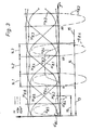
- Fig. 3 das Bewegungsdiagramm der Verdrängerkolben.
- 1 shows a sectional top view of a radial piston conveyor,
- 2 shows a central cross section I - I through the conveyor along the axis of a displacement piston pair,
- Fig. 3 shows the movement diagram of the displacement piston.
Gemäß Fig. 1 ist das Gehäuse 2 eines Förderwerkes 1 mit einer Zuführung 3 und einer dieser etwa gegenüberliegenden Abgabeöffnung 4 ausgestattete Das Gehäuse 2 umschließt einen radial wie axial selbstdichtend eingepaßten Rotor 5 , welcher auf geeignete Weise um eine Achse 6 umlaufend angetrieben ist. Der Rotor 5 weist mit ihren Mittelachsen zentral verlaufende, sich unter einem Winkel von 60° kreuzende, Portionskammern 7 bildende Bohrungen auf, welche der Aufnahme unter leichtem Schiebesitz eingepaßter Verdrängerkolben 8.1 bis 8.6 dienen. Jeweils zwei einander gegenüberliegende Verdrängerkolben sind auf geeignete Weise lösbar mittels Verbundstegen 9 zu Einheiten verbunden, die brückenartig eine in einer zentralen Aussparung 10 des Rotors 5 Platz findende Steuerkurve 11 unter Abstützung der jeweiligen Unterflächen 12 der Verdrängerkolben 8.1 bis 8.6 auf der Peripherie der Steuerkurve 11 übergreifen. Diese umfaßt einen Kompressionsabschnitt 14 , welcher aus einem konzentrischen Abschnitt 13 hervorgeht und gegen den Uhrzeigersinn folgend eine Anlaufzone, einen Evolventenabschnitt und eine Ablaufzone umfaßt, die ihrerseits in einen konzentrischen Abschnitt 15 übergeht. Diesem folgt ein sich über einen Zentriwinkel von 180° erstreckender Abschnitt, der unter stetig abnehmendem Radius in den konzentrischen Abschnitt 13 überführt, wobei der Kurvenverlauf derart ist, daß die Durchmessermaße jeweils kleiner sind als der Abstand der Unterflächen 12 zweier miteinander verbundener Verdrängerkolben. Zur Vorverdichtung des aus der Zuführöffnung 3 übernommenen Fördergutes kann der konzentrische Abschnitt 13 zugunsten eines Vorkompressionsabschnittes 16 verkürzt sein, der dem auf diesen Abschnitt auflaufenden Verdrängerkolben einen definierten Vorhub erteilt. Die Zuführöffnung 3 und die Abgabeöffnung 4 liegen einander gegenüber, wobei ihre peripheren Ausdehnungen einen auf die Achse 6 bezogenen Zentriwinkel mit einem Winkelmaß umfassen, welches im wesentlichen demjenigen des Zentriwinkels entspricht, der den Kompressionsabschnitt 14 einschließt, so daß jeweils zwei aufeinanderfolgende Portionskammern 7 mit der Abgabeöffnung 4 bzw. Zuführöffnung 3 in Verbindung stehen.1, the housing 2 of a conveyor 1 is equipped with a
Die in der Figur 1 dargestellte Funktionsphase sei Ausgangspunkt für die Betrachtung der Wirkungsweise:
- Das vorzugsweise unter leichtem Überdruck über die
Zuführöffnung 3 in deren Bereich gegen denRotor 5 strömende Füllgut hat entsprechend dieser Darstellung diePortionskammer 7 vor dem nach unten weisenden Verdrängerkolben 8.4 gefüllt und steht vor dem soeben in den Bereich derZuführöffnung 3 eingetretenen, in der Figur 1 links von diesem angeordneten Verdrängerkolben 8.5 . Wird derRotor 5 in Richtung desPfeiles 17 in Drehung versetzt, so wird der Verdrängerkolben 8.4 aufgrund des Kontaktes derUnterfläche 12 des mit diesem verbundenen Verdrängerkolbens 8.1 in seine Grundstellung zurückgezogen, d. h. in die für den Verdrängerkolben 8.3 gezeigte, so daß das Füllvolumen derPortionskammer 7 vor dem Verdrängerkolben 8.4 sein Maximum erreicht. Während des nun folgenden, denkonzentrischen Abschnitt 13 derSteuerkurve 11 einschließenden Drehwinkels Y desRotors 5 hält der Verdrängerkolben 8.4 seine Grundstellung inne, bis dieser die Position des Verdrängerkolbens 8.2 erreicht hat. Für die Betrachtung der Vorgänge bei weiterer Drehung desRotors 5 kann daher nun der Verdrängerkolben 8.2 weiterverfolgt werden, der im Begriff steht, durch Auflaufen seinerUnterfläche 12 auf denKompressionsabschnitt 14 seinen Dosierhub zu absolvieren. Dieser beginnt mit dem Auflaufen auf die·An1aufzone dieses Abschnittes, in welchem Augenblick der vorauslaufende Verdrängerkolben 8.1 die Ablaufzone erreicht hat und über diesen Teil desKompressionsabschnittes 14 bezüglich seiner Hubgeschwindigkeit fortschreitend in dem Maße zurückgenommen wird, wie die des Verdrängerkolbens 8.2 gesteigert wird. Im Augenblick der Beendigung des Hubes des vorauslaufenden Verdrängerkolbens 8.1 hat derjenige 8.2 den an die Anlaufzone anschließenden Evolventenabschnitt erreicht und übernimmt nun vorübergehend allein den Ausstoß des Füllgutes. Die vorerwähnten, unter demKompressionsabschnitt 14 zusammengefaßten Abschnitte, das sind Anlauf- und Ablaufzone sowie Evolventenabschnitt derSteuerkurve 11 , sind aus Gründen der Übersichtlichkeit in Fig. 1 nicht bezeichnet. Sie finden sich aber in Fig. 3 wobei die Anlaufzone den Drehwinkel 14.1 , der Evolventenabschnitt den Drehwinkel 14.2 und die Ablaufzone den Drehwinkel 14.3 umfassen.
- The filling material flowing against the
rotor 5, preferably under slight overpressure via thefeed opening 3 in its area, has this dar position, theportion chamber 7 is filled in front of the downward-pointing displacement piston 8.4 and stands in front of the displacement piston 8.5 which has just entered the region of thefeed opening 3 and is arranged to the left of this in FIG. 1. If therotor 5 is rotated in the direction of thearrow 17, the displacer piston 8.4 is retracted into its basic position due to the contact of thelower surface 12 of the displacer piston 8.1 connected to it, ie into the position shown for the displacer piston 8.3, so that the filling volume of theportion chamber 7 reaches its maximum in front of the displacement piston 8.4. During the rotation angle Y of therotor 5 which now follows theconcentric section 13 of thecontrol cam 11, the displacement piston 8.4 holds its basic position until it has reached the position of the displacement piston 8.2. For the consideration of the processes with further rotation of therotor 5, the displacement piston 8.2 can now be followed up, which is about to complete its metering stroke by running itslower surface 12 onto thecompression section 14. This begins with the run-up to the start-up zone of this section, at which moment the preceding displacement piston 8.1 has reached the discharge zone and, via this part of thecompression section 14, its stroke speed is gradually reduced to the extent that that of the displacement piston 8.2 is increased. At the moment the stroke of the leading displacement piston 8.1 ends, the one 8.2 has reached the involute section adjoining the start-up zone and now temporarily assumes only the discharge of the filling material. The aforementioned, under thecompression section 14 too Collected sections, that is the start-up and run-off zone and involute section of thecontrol cam 11, are not shown in FIG. 1 for reasons of clarity. However, they can be found in FIG. 3, the run-up zone comprising the angle of rotation 14.1, the involute section comprising the angle of rotation 14.2 and the run-off zone comprising the angle of rotation 14.3.
Anhand der Fig. 3 wird nachfolgend noch einmal der Wirkungsablauf nachvollzogen. Es wird dabei wiederum der Verdrängerkolben 8.4 verfolgt, der zunächst entsprechend der Hublinie HS.4 in dem Vorkompressionsabschnitt 16 unter mäßiger Beschleunigung a'8.4 um einen definierten Hubbetrag unter Vorkompression des in der zugehörigen Portionskammer 7 befindlichen Füllgutes radial nach außen gegen das in diesem Bereich geschlossene Gehäuse 2 angehoben wird. Über den Rest des den Vorkompressionsabschnitt 16 mit umfassenden Abschnittes 13 wird die am Ende des vorletztgenannten Abschnittes 16 erreichte Hubposition beibehalten, nachdem die Hubgeschwindigkeit unter mäßiger Verzögerung -a'8.4 zurückgenommen wurde. Der Verdrängerkolben 8.4 gelangt nunmehr über den Kompressionsabschnitt 14 der Steuerkurve 11 , über welchem Bereich die Portionskammer 7 mit der Abgabeöffnung 4 Verbindung hat, und beginnt unter mäßiger Beschleunigung a8.4 während des Überlaufes der Anlaufzone 14.1 mit dem Ausstoß des Füllgutes aus der Portionskammer 7 Gleichzeitig wurde der vorauslaufende Verdrängerkolben 8.3 durch Überlaufen der Ablaufzone 14.3 unter einer zu der Beschleunigung a8.4 symmetrisch verlaufenden Verzögerung -a8.3 in seiner Hubgeschwindigkeit zurückgenommen, und diese zum Ende des Kompressionsabschnittes 14 hin auf Null gebracht, was mit dem Erreichen des Hub-Maximums zusammenfällt. In diesem Augenblick ist der Verdrängerkolben 8.4 über den Evolventenabschnitt 14.2 gelangt, welcher dem erstgenannten die gleichförmige Hubgeschwindigkeit v8.4 erteilt, d. h. seine Beschleunigung auf Null zurücknimmt. Der folgende Durchgang durch die Ablaufzone 14.3 verursacht eine Verzögerung -a8.4 der Hubgeschwindigkeit, während welcher der nachfolgende Verdrängerkolben 8.5 bezüglich seiner Hubgeschwindigkeit symmetrisch zu der des Verdrängerkolbens 8.4 einer Beschleunigung a8.5 dadurch unterworfen wird, daß dieser gleichzeitig die Anlaufzone 14.1 durchläuft. Diesem Bewegungsprofil wird jeder Verdrängerkolben gegenüber seinem vorauslaufenden mit einer Phasenverschiebung von 60° unterworfen, so daß während der Wirksamkeit der Anlaufzone 14.1 und Ablaufzone 14.3 jeweils zwei Verdrängerkolben an dem Masseausstoß beteiligt sind, während der Evolventenabschnitt 14.2 jeweils nur einen derselben zu betätigen hat. Erfolgt der Antrieb des Rotors 5 durch einen in seinem Drehwinkel überwachbaren Antriebsmotor, so läßt sich mit dem beschriebenen Förderer mit Hilfe einer Drehwinkel-Rückmeldung ein dem Ausstoßvolumen proportionales Signal ableiten. Es ist daher mit dieser Vorrichtung möglich, durch aufeinanderfolgendes Abfahren gleicher Drehwinkel gleiche Portionen zu erzeugen. Als am besten geeignet zeigt sich für diesen Antriebsfall der Schrittmotor.3, the sequence of effects will be reproduced again below. Again, the displacement piston 8.4 is tracked, which initially corresponds to the stroke line HS.4 in the
- 1 Förderwerk1 conveyor
- 2 Gehäuse2 housings
- 3 Zuführöffnung3 feed opening
- 4 Abgabeöffnung4 dispensing opening
- 5 Rotor5 rotor
- 6 Achse6 axis
- 7 Portionskammer7 portion chamber
- 8.1 Verdrängerkolben8.1 Displacement pistons
- 8.2 " "8.2 ""
- 8.3 " "8.3 ""
- 8.4 "8.4 "
- 8.5 " "8.5 ""
- 8.6 "8.6 "
- 9 Verbundsteg9 composite web
- 10 Aussparung10 recess
- 11 Steuerkurve11 control curve
- 12 Unterfläche12 lower surface
- 13 konzentrischer Abschnitt13 concentric section
- 14 Kompressionsabschnitt14 compression section
- 14.1 Anlaufzone14.1 Start-up zone
- 14.2 Evolventenabschnitt14.2 Involute section
- 14.3 Ablaufzone14.3 Drain zone
- 15 konzentrischer Abschnitt15 concentric section
- 16 Vorkompressionsabschnitt16 pre-compression section
- 17 Pfeil17 arrow
-
Drehwinkel des Rotors
 Angle of rotation of the rotor
 - a'8.4 Beschleunigung des Verdrängerkolbens 8.4a ' 8.4 Acceleration of the displacement piston 8.4
- a 8.4 " " " " " 8.4a 8.4 """""8.4
- -a'8.4 Verzögerung des Verdrängerkolbens 8.4-a ' 8.4 Deceleration of the displacement piston 8.4
- -a8.4 " " " " " 8.4-a 8.4 """""8.4
- v8.4 Geschwindigkeit des Verdrängerkolbens 8.4v 8.4 Velocity of the displacement piston 8.4
- H8.4 Hub des Verdrängerkolbens 8.4H 8.4 Stroke of the displacement piston 8.4
Claims (3)
Applications Claiming Priority (2)
| Application Number | Priority Date | Filing Date | Title |
|---|---|---|---|
| DE19863617396 DE3617396A1 (en) | 1986-05-23 | 1986-05-23 | DEVICE FOR CONVEYING PASTE-LIKE MASSES |
| DE3617396 | 1986-05-23 |
Publications (2)
| Publication Number | Publication Date |
|---|---|
| EP0246440A2 true EP0246440A2 (en) | 1987-11-25 |
| EP0246440A3 EP0246440A3 (en) | 1988-06-08 |
Family
ID=6301487
Family Applications (1)
| Application Number | Title | Priority Date | Filing Date |
|---|---|---|---|
| EP87105174A Withdrawn EP0246440A3 (en) | 1986-05-23 | 1987-04-08 | Conveying device for pasty products |
Country Status (7)
| Country | Link |
|---|---|
| US (1) | US4730366A (en) |
| EP (1) | EP0246440A3 (en) |
| JP (1) | JPS6352016A (en) |
| AU (1) | AU7316187A (en) |
| CA (1) | CA1254078A (en) |
| DE (1) | DE3617396A1 (en) |
| NZ (1) | NZ220358A (en) |
Family Cites Families (10)
| Publication number | Priority date | Publication date | Assignee | Title |
|---|---|---|---|---|
| DE353008C (en) * | 1918-10-10 | 1922-05-08 | Ludwig Sautter Dipl Ing Dr Ing | Device for measuring gas or liquid quantities with a rotating measuring room system |
| US2666229A (en) * | 1949-11-08 | 1954-01-19 | Clarence W Vogt | Method and apparatus for producing accurately measured plastic masses |
| DE1210997B (en) * | 1961-10-14 | 1966-02-17 | Benz & Hilgers G M B H | Device for dosing liquid, powdery, granular or plastic substances |
| DE1177359B (en) * | 1962-06-09 | 1964-09-03 | Benz & Hilgers G M B H | Device for dosing and filling or molding plastic material such as butter, margarine, ice cream and the like like |
| DE1185116B (en) * | 1962-06-26 | 1965-01-07 | Balthasar Hasselbach | Rotary valve |
| US3489104A (en) * | 1966-12-23 | 1970-01-13 | Werner & Pfleiderer | Dough-cutting machine |
| FR2127456A5 (en) * | 1971-03-03 | 1972-10-13 | Hely Joly Georges | Continuous automatic prepn machine - for reconstituted beefsteaks |
| DE3136387C2 (en) * | 1981-09-14 | 1984-11-29 | Deutsche Gerätebau GmbH, 4796 Salzkotten | Device for measuring amounts of liquid |
| DE3409517C2 (en) * | 1984-03-15 | 1986-10-02 | Nordischer Maschinenbau Rud. Baader GmbH + Co KG, 2400 Lübeck | Device for conveying pasty masses |
| DE3511288A1 (en) * | 1985-03-28 | 1986-10-02 | Manfred Engler GmbH Maschinenbau, 7100 Heilbronn | Metering device |
-
1986
- 1986-05-23 DE DE19863617396 patent/DE3617396A1/en active Granted
-
1987
- 1987-04-08 EP EP87105174A patent/EP0246440A3/en not_active Withdrawn
- 1987-05-18 AU AU73161/87A patent/AU7316187A/en not_active Abandoned
- 1987-05-19 NZ NZ220358A patent/NZ220358A/en unknown
- 1987-05-20 US US07/052,771 patent/US4730366A/en not_active Expired - Fee Related
- 1987-05-20 CA CA000537489A patent/CA1254078A/en not_active Expired
- 1987-05-22 JP JP62124077A patent/JPS6352016A/en active Granted
Also Published As
| Publication number | Publication date |
|---|---|
| US4730366A (en) | 1988-03-15 |
| EP0246440A3 (en) | 1988-06-08 |
| JPS6352016A (en) | 1988-03-05 |
| NZ220358A (en) | 1989-10-27 |
| CA1254078A (en) | 1989-05-16 |
| DE3617396C2 (en) | 1988-06-23 |
| JPH0464569B2 (en) | 1992-10-15 |
| DE3617396A1 (en) | 1987-11-26 |
| AU7316187A (en) | 1987-11-26 |
Similar Documents
| Publication | Publication Date | Title |
|---|---|---|
| DE69522999T2 (en) | Displacement pump with rotary valve | |
| DE2211696A1 (en) | Extrusion process and device | |
| DE2821755A1 (en) | VIBRATION COMPRESSION ROLLER | |
| DE69011630T2 (en) | Automatic paint spraying machine. | |
| DE4136828C2 (en) | Flow divider pump | |
| DE2260765C3 (en) | Container filling device | |
| DE3731817C2 (en) | ||
| DE3209640A1 (en) | HYDRAULIC PUMP | |
| DE3837325C2 (en) | ||
| DE3410302C2 (en) | Device for filling metered amounts of a liquid to viscous substance, in particular chocolate mass | |
| DE19953183C2 (en) | Microdispenser | |
| DE3617396C2 (en) | ||
| EP0976968A2 (en) | Piston pumps for the transport of lubricant to different points in a machine, a conveyor or an escalator | |
| DE2717323A1 (en) | FUEL INJECTION PUMP | |
| DE2419581A1 (en) | PISTON MACHINE | |
| DE2857494A1 (en) | Rotary positive displacement fluid machines - has lubricating oil and sliding vane vacuum pumps in rotatable hollow shaft and separated by plate | |
| DE3409517C2 (en) | Device for conveying pasty masses | |
| DE2121006C3 (en) | Method and device for portioning and twisting off a pasty mass | |
| DE3734926C2 (en) | ||
| DE4314728C2 (en) | Roller press for extruding plastic masses | |
| DE2821141C2 (en) | ||
| DE2816384C2 (en) | Lubricant feed pump | |
| DE3440543A1 (en) | FLUIDIC RADIAL PISTON MACHINE | |
| DE3734956A1 (en) | STRAND MANUFACTURING MACHINE | |
| DE19834599C2 (en) | Liquid feeding system |
Legal Events
| Date | Code | Title | Description |
|---|---|---|---|
| PUAI | Public reference made under article 153(3) epc to a published international application that has entered the european phase |
Free format text: ORIGINAL CODE: 0009012 |
|
| AK | Designated contracting states |
Kind code of ref document: A2 Designated state(s): AT BE CH DE ES FR GB IT LI LU NL SE |
|
| 17P | Request for examination filed |
Effective date: 19871026 |
|
| PUAL | Search report despatched |
Free format text: ORIGINAL CODE: 0009013 |
|
| AK | Designated contracting states |
Kind code of ref document: A3 Designated state(s): AT BE CH DE ES FR GB IT LI LU NL SE |
|
| 17Q | First examination report despatched |
Effective date: 19891201 |
|
| STAA | Information on the status of an ep patent application or granted ep patent |
Free format text: STATUS: THE APPLICATION IS DEEMED TO BE WITHDRAWN |
|
| 18D | Application deemed to be withdrawn |
Effective date: 19901103 |
|
| RIN1 | Information on inventor provided before grant (corrected) |
Inventor name: METTE, MANFRED, DR.-ING. |