EP0246311B1 - Water barrier - Google Patents
Water barrier Download PDFInfo
- Publication number
- EP0246311B1 EP0246311B1 EP19860907191 EP86907191A EP0246311B1 EP 0246311 B1 EP0246311 B1 EP 0246311B1 EP 19860907191 EP19860907191 EP 19860907191 EP 86907191 A EP86907191 A EP 86907191A EP 0246311 B1 EP0246311 B1 EP 0246311B1
- Authority
- EP
- European Patent Office
- Prior art keywords
- particles
- sheet
- adhesive
- layer
- membrane
- Prior art date
- Legal status (The legal status is an assumption and is not a legal conclusion. Google has not performed a legal analysis and makes no representation as to the accuracy of the status listed.)
- Expired - Lifetime
Links
Images
Classifications
-
- E—FIXED CONSTRUCTIONS
- E02—HYDRAULIC ENGINEERING; FOUNDATIONS; SOIL SHIFTING
- E02D—FOUNDATIONS; EXCAVATIONS; EMBANKMENTS; UNDERGROUND OR UNDERWATER STRUCTURES
- E02D31/00—Protective arrangements for foundations or foundation structures; Ground foundation measures for protecting the soil or the subsoil water, e.g. preventing or counteracting oil pollution
- E02D31/002—Ground foundation measures for protecting the soil or subsoil water, e.g. preventing or counteracting oil pollution
- E02D31/004—Sealing liners
-
- E—FIXED CONSTRUCTIONS
- E02—HYDRAULIC ENGINEERING; FOUNDATIONS; SOIL SHIFTING
- E02B—HYDRAULIC ENGINEERING
- E02B3/00—Engineering works in connection with control or use of streams, rivers, coasts, or other marine sites; Sealings or joints for engineering works in general
- E02B3/16—Sealings or joints
-
- E—FIXED CONSTRUCTIONS
- E02—HYDRAULIC ENGINEERING; FOUNDATIONS; SOIL SHIFTING
- E02D—FOUNDATIONS; EXCAVATIONS; EMBANKMENTS; UNDERGROUND OR UNDERWATER STRUCTURES
- E02D19/00—Keeping dry foundation sites or other areas in the ground
-
- E—FIXED CONSTRUCTIONS
- E04—BUILDING
- E04B—GENERAL BUILDING CONSTRUCTIONS; WALLS, e.g. PARTITIONS; ROOFS; FLOORS; CEILINGS; INSULATION OR OTHER PROTECTION OF BUILDINGS
- E04B1/00—Constructions in general; Structures which are not restricted either to walls, e.g. partitions, or floors or ceilings or roofs
- E04B1/62—Insulation or other protection; Elements or use of specified material therefor
- E04B1/66—Sealings
-
- Y—GENERAL TAGGING OF NEW TECHNOLOGICAL DEVELOPMENTS; GENERAL TAGGING OF CROSS-SECTIONAL TECHNOLOGIES SPANNING OVER SEVERAL SECTIONS OF THE IPC; TECHNICAL SUBJECTS COVERED BY FORMER USPC CROSS-REFERENCE ART COLLECTIONS [XRACs] AND DIGESTS
- Y10—TECHNICAL SUBJECTS COVERED BY FORMER USPC
- Y10S—TECHNICAL SUBJECTS COVERED BY FORMER USPC CROSS-REFERENCE ART COLLECTIONS [XRACs] AND DIGESTS
- Y10S428/00—Stock material or miscellaneous articles
- Y10S428/913—Material designed to be responsive to temperature, light, moisture
-
- Y—GENERAL TAGGING OF NEW TECHNOLOGICAL DEVELOPMENTS; GENERAL TAGGING OF CROSS-SECTIONAL TECHNOLOGIES SPANNING OVER SEVERAL SECTIONS OF THE IPC; TECHNICAL SUBJECTS COVERED BY FORMER USPC CROSS-REFERENCE ART COLLECTIONS [XRACs] AND DIGESTS
- Y10—TECHNICAL SUBJECTS COVERED BY FORMER USPC
- Y10T—TECHNICAL SUBJECTS COVERED BY FORMER US CLASSIFICATION
- Y10T428/00—Stock material or miscellaneous articles
- Y10T428/24—Structurally defined web or sheet [e.g., overall dimension, etc.]
- Y10T428/24355—Continuous and nonuniform or irregular surface on layer or component [e.g., roofing, etc.]
- Y10T428/24372—Particulate matter
- Y10T428/24413—Metal or metal compound
-
- Y—GENERAL TAGGING OF NEW TECHNOLOGICAL DEVELOPMENTS; GENERAL TAGGING OF CROSS-SECTIONAL TECHNOLOGIES SPANNING OVER SEVERAL SECTIONS OF THE IPC; TECHNICAL SUBJECTS COVERED BY FORMER USPC CROSS-REFERENCE ART COLLECTIONS [XRACs] AND DIGESTS
- Y10—TECHNICAL SUBJECTS COVERED BY FORMER USPC
- Y10T—TECHNICAL SUBJECTS COVERED BY FORMER US CLASSIFICATION
- Y10T428/00—Stock material or miscellaneous articles
- Y10T428/24—Structurally defined web or sheet [e.g., overall dimension, etc.]
- Y10T428/24355—Continuous and nonuniform or irregular surface on layer or component [e.g., roofing, etc.]
- Y10T428/24372—Particulate matter
- Y10T428/24421—Silicon containing
- Y10T428/2443—Sand, clay, or crushed rock or slate
-
- Y—GENERAL TAGGING OF NEW TECHNOLOGICAL DEVELOPMENTS; GENERAL TAGGING OF CROSS-SECTIONAL TECHNOLOGIES SPANNING OVER SEVERAL SECTIONS OF THE IPC; TECHNICAL SUBJECTS COVERED BY FORMER USPC CROSS-REFERENCE ART COLLECTIONS [XRACs] AND DIGESTS
- Y10—TECHNICAL SUBJECTS COVERED BY FORMER USPC
- Y10T—TECHNICAL SUBJECTS COVERED BY FORMER US CLASSIFICATION
- Y10T428/00—Stock material or miscellaneous articles
- Y10T428/25—Web or sheet containing structurally defined element or component and including a second component containing structurally defined particles
- Y10T428/259—Silicic material
-
- Y—GENERAL TAGGING OF NEW TECHNOLOGICAL DEVELOPMENTS; GENERAL TAGGING OF CROSS-SECTIONAL TECHNOLOGIES SPANNING OVER SEVERAL SECTIONS OF THE IPC; TECHNICAL SUBJECTS COVERED BY FORMER USPC CROSS-REFERENCE ART COLLECTIONS [XRACs] AND DIGESTS
- Y10—TECHNICAL SUBJECTS COVERED BY FORMER USPC
- Y10T—TECHNICAL SUBJECTS COVERED BY FORMER US CLASSIFICATION
- Y10T428/00—Stock material or miscellaneous articles
- Y10T428/26—Web or sheet containing structurally defined element or component, the element or component having a specified physical dimension
- Y10T428/266—Web or sheet containing structurally defined element or component, the element or component having a specified physical dimension of base or substrate
-
- Y—GENERAL TAGGING OF NEW TECHNOLOGICAL DEVELOPMENTS; GENERAL TAGGING OF CROSS-SECTIONAL TECHNOLOGIES SPANNING OVER SEVERAL SECTIONS OF THE IPC; TECHNICAL SUBJECTS COVERED BY FORMER USPC CROSS-REFERENCE ART COLLECTIONS [XRACs] AND DIGESTS
- Y10—TECHNICAL SUBJECTS COVERED BY FORMER USPC
- Y10T—TECHNICAL SUBJECTS COVERED BY FORMER US CLASSIFICATION
- Y10T428/00—Stock material or miscellaneous articles
- Y10T428/31504—Composite [nonstructural laminate]
- Y10T428/31652—Of asbestos
- Y10T428/31667—Next to addition polymer from unsaturated monomers, or aldehyde or ketone condensation product
Definitions
- the present invention relates to waterproofing processes and materials, and in particular a sheet laminated with non-hydrated granular bentonite for applications for waterproofing.
- U.S. Patent No. 4,467,015 shows another type of structure that has two layers, and which can be formed into a roll. Each layer includes a sheet of water permeable material and a coating of dry particles of bentonite on one surface of the sheet. An adhesive is used for applying the particles of bentonite to the water permeable material, and the bentonite particles are placed so that they face the surface of the structure that is to be waterproofed.
- the sheet shown in Patent 4,467,015 has inherent problems with the cardboard or water permeable sheet, namely migration of water and leaking at the joints until the material attempts to self-seal. The material also is susceptible to rain damage and it needs protection against the weather when installed, until it is covered by backfilling or the like.
- U.S. Patent No. 4,212,671 relates to a method and apparatus for making decorative inlaid types of resilient sheet materials and describes an apparatus for applying decorative chips, flakes and granules to a polymeric sheet.
- the present invention relates to a waterproofing sheet and a method and apparatus for making the same wherein the sheet is made of an impervious flexible material or membrane (impervious to water) for example a polymeric material, and has a layer of particles which are capable of swelling when in contact with water, for example, granular bentonite adhering to one surface thereof.
- the particles for example bentonite particles, also adhere to each other to form the layer that has structural integrity sufficient to permit the sheets to be rolled or handled as large sheets.
- a waterproofing sheet comprising a membrane of water impermeable material, and a coating of particles capable of swelling when in contact with water adhered with an adhesive material to the membrane and to adjacent particles, the coating being of a thickness equal to a plurality of layers of particles.
- the invention also provides a waterproofing composite sheet comprising a water impervious membrane and a composite layer of adhesives and particles that are adhered together and to the membrane, said particles comprising sodium montmorillonite and said composite layer having a thickness to obtain waterproofing action to the sodium montmorillonite particles.
- a method of producing a self sealing waterproofing sheet composite comprising the steps of moving a water-impervious sheet material in a first direction; applying a spray adhesive to the upper surface of the sheet; depositing a single thickness layer of particulate material capable of swelling when in contact with water, like sodium bentonite in the first layer of adhesive to form a first layer of particles covering the sheet; and adding subsequent layers of adhesives and single thickness layers of particles until the composite layer of particles reaches the desired depth.
- an apparatus for applying layers of particles to sheet material including a conveyor, said conveyor having a length inclined upwardly in the direction of movement with respect to the horizontal; means for supplying a sheet material to the conveyor; and a plurality of adhesive and particle applying stations spaced at locations along said conveyor and spaced therefrom, above a sheet moved by the conveyor, each such station comprising an adhesive spray means for spraying a layer of adhesive onto a surface below, and a particle applying hopper adapted to dispense a selected amount of particles onto a previous applied layer of adhesive, so that each layer of adhesive is covered with a layer of particles.
- the said particles comprise sodium montmorillonite of a classified mesh size.
- the adhesive is used for adhering the first layer of particles to the membrane, and a separate layer of adhesive is applied over each subsequent layer of particles prior to the time the next layer of particles is applied to cause the adhesion of the particles with respect to the membrane and each other.
- Said membrane preferably comprises a high density polyethylene capable of being rolled into a roll after the layers of particles have been applied.
- the sodium montmorillonite particles are adhered to the sheet with an adhesive comprising adhesive solids in concentration from five to about one hundred percent by weight selected from the group consisting of butelenes, butyl rubber, acrylics, propenes, styrene-butadiene, nitriles, vinyls and water soluble cellulosics, saccharides, gums, and proteins.
- the adhesives are preferably mixed with bentonite in ratios of between three and fifty percent by weight, with the three pecent comprising the adhesive.
- the layer of sodium montmorillonite particles is spaced from the edges of the water impervious membrane, to leave a lap joint strip of uncoated membrane for overlapping edge portions of adjacent membranes when in position on a structure.
- the method of producing a self-sealing waterproofing sheet in accord with the invention preferably includes the steps of inclining the plane of the sheet with respect to a horizontal plane as it is moved along the conveyor, and moving the sheet in the first direction upwardly at the incline for each subsequent application of layers and vibrating the sheet at a desired frequency and amplitude in a location substantially adjacent the location of the depositing of the particles and in a direction substantially perpendicular to the plane of the sheet.
- the method includes the step of selecting the rate of feed of adhesive and bentonite, and the incline of the sheet, relative to the amplitude of vibration to provide a layer of particles that is a single particle deep across the width of the sheet on top of each layer of adhesive.
- the apparatus of the invention preferably includes sizing roll means for compressing the sheet and applied layers of particles to a desired, substantially uniform thickness.
- the two intersecting margins (one side and one end) of a sheet are made so that there are no particles for a short distance along the edges of the polymeric sheet, to provide for a sealing overlap of one edge of the membrane onto the edge of a second sheet of the membrane.
- This provides seal lines that can be caulked, welded or adhesively sealed, to create a tight cover of panels over the structure.
- a preferred aspect of the present invention utilizes a layer of water impermeable polymer, and is usually installed polymer side out.
- the bentonite is protected from rain damage by the polymer when it is put into place. If a tough polymer is used, such as high density polyethylene, a product that is not susceptible to damage is achieved.
- the bentonite layer eliminates the need for tightly adhering a membrane to the wall or roof structure to stop water migration, because if water tends to get under the membrane and contacts the bentonite, the bentonite is self-sealing and swells to stop any migration immediately. Water migration between membrane and a substrate has been a cause of great unsatisifaction of users of buildings, and has been the cause of innumerable lawsuits.
- an apparatus for manufacturing the waterproofing sheet composites which provides for individually adhering a single particle thick layers onto the membrane, with a layer of adhesive, and then subsequently adding additional single particle thick layers until the desired depth of the particles is achieved.
- the backing membrane as disclosed high density polythene, is carried on a conveyor up an incline, and a spray bar is positioned to apply a thin layer of adhesive directly to the polyethylene membrane.
- the adhesive is selected to be one that adheres to the membrane, and a wide range of adhesives will work.
- a single particle thick layer of bentonite particles is deposited on the adhesive above a conveyor- membrane agitator that provides a frequency of vibration to the conveyor in a direction perpendicular to the conveyor belt so that the particles tend to dance upwardly and form a standing wave of particles that lift the belt and tend to fall downwardly under gravity.
- the conveyor belt is inclined upwardly in its path of travel, and the particles tending to move downwardly will fall into place on the adhesive layer and will be held in place in a single thickness of particles.
- the rate of feed of the bentonite particles can be controlled in a conventional manner so that excessive particles are not provided. A uniform single particle thick layer is thus provided on the membrane.
- the conveyor moves the membrane to a second station where an additional thin layer of adhesive is sprayed onto the previously deposited layer of particles, and then another layer of particles is deposited on the second layer of adhesive, in the same manner as described.
- the second layer of particles increases or doubles the thickness of the particles on the membrane, and this process is repeated in sequence until a desired depth has been deposited on the membrane.
- the membrane formed into the composite waterproofing sheet is carried on the conveyor belt downwardly, and can be passed through sizing rollers that will compress the layers of particles into the adhesive to insure good ahere- nce as well as a uniform thickness of the finished product.
- the finished composite waterproofing sheet product is then placed into rolls for storage and shipment to the job site, where it is installed as described above or is cut into individual panels of desired size.
- the method of manufacture makes it possible to provide rapid and accurate formation of the bentonite layers, thereby increasing efficiency.
- Figure 1 illustrates a finished composite waterproofing sheet product 12, made according to the present invention and comprises a membrane 10 of material that is impervious to water, such as high density polyethylene, and a thickness or waterproofing layer of bentonite or sodium montmorillonite indicated at 11.
- the layer 11 is meant to indicate a finished thickness of bentonite made up of a number of layers, each having a thickness of an individual bentonite particle with interspersed adhesive layers, made into a sandwich type composite waterproofing sheet 10.
- an edge portion 13 of the membrane or sheet 10 may be left without the layer 11 of particles, as shown in Figure 2, so that the sheets or panels can be lapped.
- the lapped edge portion 13 in Figure 2 along a longitudinal edge, and if smaller panels such as 1.2 m (4ft.) by 1.2 m (4ft.) panels are used, an edge portion 14 of the membrane will be left uncoated along one end of the panel as well.
- the panels or long strips or sheets
- the composite waterproofing sheets are installed with the water impervious membrane facing outwardly to the elements.
- the composite structure comprises a flexible water impervious membrane in sheet form having a layer of particles, for waterproofing, preferably bentonite particles, on the surface at a desired depth.
- Adhesives that provide proper holding action are also important. While the prior art shows various adhesives that will work with bentonite, bentonite is highly reactive to many monovalant, divalant and trivalant materials. Bentonite also may form a permanent association with numerous other elements and compounds, and such products should be avoided in making the composite waterproofing sheets so that the bentonite particles do not react and lose their desirable property of swelling when contacted by water. When reactions do occur, or association of the bentonite particles with other elements occur, the waterproofing capabilities are degraded, because the bentonite material does not have the ability to swell and waterproof.
- Adhesive materials are available as emulsions with water, solutes, concentrates, hot melts and often in homo or copolymer status. Almost any adhesive originating from a solvent, emulsion with water, hot melt or water emulsified solid may be used, and the choice is determined by the ability to wet, its stickiness, the polar activity and the final adhesion performance. The choice is influenced by price, toxicity, availability, or environmental considerations as well. The addition of wetting agents, emulsifiers, dispersants and preservatives for latexes can cause deterioration of the bentonite's ability to waterproof or reseal, so use of products may be minimized.
- Adhesion to high density polyethylene has been difficult, and a common procedure to enhance adhesion is to chemically disturb the surface of the polyethylene or polymer membrane just prior to the application of the adhesive, for example by treating it with ozone. This brings in time limitations which means that the membrane has to be coated quite quickly because the molecules that are affected by the treatment migrate back to their original smooth alignment relatively fast.
- the total thickness of the layers of bentonite particles is built up to in the range of 3.18 mm (1/8 inch) to 6.35 mm (1/4 inch) thick, and thus a method of continuously achieving a permanent adhesion to the polyethylene membrane is required.
- the surface of the polyethylene preferably is roughened, and as shown herein, it can be done by stretching the polyethylene to microscopically "craze" the surface of the polyethylene.
- the amount and the direction of the tension applied to the membrane is determined by the thickness of the membrane. Generally, tensioning the membrane to about 207 KNm- 2 (30 Ibs per square inch) is acceptable for thicknesses of 0.051 mm to 0.508 mm (2 to 20 mils).
- the membrane used herein is most preferably in 'the range of 0.508 mm (20 mils), but the preferred range is 0.381 mm to 2.54 mm (15 to 100 mils) in thickness.
- tensioning can be done by passing the polyethylene membrane over rollers which apply a stretch between pinch drive rollers.
- the adhesive used must wet the polyethylene surface for good adhesion, and low surface tension solvent systems provide a suitable vehicle to carry the adhesive.
- Aliphatics, aldehydes, ketones, carbon/halide and ring compounds all have utilization.
- Common carriers/solvents include toluene, lower molecular weight alcohols, methyl ketone and water.
- the following products act as suitable adhesives:
- the adhesive solids should be present in concentrations from about 5 to 100% by weight, and are mixed with bentonite in ratios of between 3 and 50% by weight of the adhesive relative to the particles (bentonite).
- the method of prestretching the polyethylene for applying the adhesive is illustrated schematically, and is a conventional method for stretching sheets of materials.
- the structure shown therein can constitute the polyethylene supply of the main machine which will be discussed.
- a roll of polyethylene membrane material or other suitable sheet material is indicated at 20, and the membrane is passed through a pair of pinch rollers 21, which are driven from a motor 21A at a first speed and clamp the polyethylene membrane so it is driven at this set rate.
- the polyethylene is then run over suitable tensioning rollers indicated generally at 22 and 23 (more tensioning rollers may be used), and then the membrane is passed through a pair of pinch drive rollers 26.
- the drive rollers 26 are also driven by a suitable motor 26A, and tension can be applied to the membrane by driving the rollers 26 at a different (faster) lineal speed than the rollers 21.
- the membrane will be tensioned because of the differential in speed.
- Another way of stretching the membrane would be to run a section of sheet material between the first and second sets of pinch rollers, and then move the rollers, or guide rollers 22 and 23, in opposite directions (indicated by arrows) to stretch the membrane 10 a desired amount, and then subsequently run an additional length of material onto the stretching idler rollers.
- the method of tensioning or stretching the polyethylene membrane (or other membrane) can be used applying known principles, and thus the showing is done only schematically herein. Additionally, treated polyethylene can be obtained that has the ozone treatment previously mentioned.
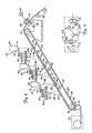
- FIG 3 illustrates schematically the method of applying adhesive and particles to the water impervious membrane.
- the material supply indicated generally at 30, which can comprise a roll, if the membrane is treated, or the stretching rollers and drive shown in Figure 6, provides a continuous sheet of the membrane 10 that passes over a guide roller 31, and then is fed onto the top of conveyor belt assembly indicated generally at 32 having an endless belt 32A.
- the conveyor belt assembly is schematically represented as having a drive roller 33 at its upper end, and an idler roller 34 at its lower end over which the belt 32A is mounted.
- the conveyor belt 32A and thus the membrane sheet 10 are inclined in the range of 20° to 50° with respect to a horizontal plane.
- the conveyor belt incline is matched with a downwardly extending conveyor section 38 thay may be rollers or a conveyor belt and which is shown only partially, on which the membrane sheet 10 will run after the particles have been applied to form the composite waterproofing sheet 12.
- the downward incline is to insure that the membrane 10 will be carried upwardly by the conveyor belt 32A because there will be a downward component of loading tending to keep the membrane 10 moving upwardly on the incline. There will be some friction between the conveyor and the undersurface of the membrane as well. If needed, drive rollers can be utilized.
- the conveyor belt can be open mesh, a runner coated belt or any desired construction.
- the membrane sheet 10 has a surface that faces upwardly and as it is carried up the incline, the membrane 10 passes through a first particle application station indicated generally at 35, a second station indicated generally at 36, and a third station indicated generally at 37. More application stations are generally used, but the stations illustrated show the method.
- Each station 35, 36 and 37 includes an adhesive supply 40 feeding an adhesive through a feed control 40A to a spray bar 41 that extends transversely across the width of the membrane sheet 10. If the membrane is in the range of 1.2 m (4 feet) wide, the adhesive bar would be that long. Known adhesive spray bars can be utilized.
- the adhesive used can be selected from the group previously listed, and as shown by the dotted line representations at 42, the adhesive is sprayed in a thin layer onto the moving membrane in a first processing region indicated generally at 43.
- the coated membrane 10 moves upwardly a distance on the inclined conveyor, and a second portion of the staton 35, comprising a bentonite hopper 46 having a transversely extending feed section 47 of conventional design also controlled as to rate of feed with a conventional rate of feed control 49 applies a uniform, relatively thin line of bentonite particles indicated at 48 across the membrane.
- the bentonite particles drop onto the conveyor, immediately above or in the vicinity of a rotating beater bar 52 that is mounted in a suitable manner on bearings at opposite ends and is driven from a motor 53 to rotate at a desired speed.
- the beater bars 52 has two radial longitudinal extending lugs 54 on opposite sides thereof (diametrically opposed). Two positions of the lugs are shown in Figures 4 and 5, one in dotted lines.
- the lugs 54 strike the conveyor belt on its undersurface and vibrate it upwardly to bounce the bentonite particles upwardly from the belt and the membrane (at least particles that have not initially adhered to the layer of adhesive) and the loose particles then will tend to fall back into the region shown at 55 in Figure 3.
- a type of "standing wave" of individual particles is created because they will tend to fall back onto the membrane and be replaced by new particles bounced in the air by the beater bar.
- the particles which have touched the adhesive move upwardly with the membrane, but are locked in place.
- This low frequency, vertical vibrating action dislodges non-adhered bentonite particles, and insures that a totally adhered, uniform single particle thick layer is applied to the first adhesive layer in station 35.
- the second sprayer bar 41 applies a thin layer of adhesive in a region shown at 57, which would be applied on the upper surface of the first layer of bentonite particles, as well as flowing slightly in between any spaces in the bentonite particles forming the first layer.
- the rate of feed of adhesive can be controlled with feed control 40A.
- a second bentonite hopper 46 with a feed assembly 47 and rate of feed control 49 will apply another individual particle layer onto the first layer of particles and the second layer of adhesive applied in the region 57.
- the hopper 46 at the second station 36 is also immediately above a beater bar 52 that is driven from a motor 53 as well. This beater bar acts as before and forms a second standing wave or particles to cause a second, single particle thick layer of particles to form on top of the first layer of particles, so that now there are two layers of particles adhered to the upper surface of the membrane 10.
- the adhesive is applied in a section 60 of the membrane.
- a third layer of adhesive is applied in section 60 with a third spray bar 41, and when the applied thin layer of adhesive is moved up under the third station bentonite hopper 46, the feed of particles from the feed section 47 of the third station 37 falls down onto the new or fresh adhesive layer to form a third layer of particles on the membrane.
- the particles are deposited above a third beater bar 52 driven from a motor 53 to form a standing wave 55 at station 37, forming the uniform, single particle depth layer of material.
- the number of layers of particle material desired, to achieve the desired thickness determines the number of individual stations that are utilized. This process may be used for forming adhering layers of particles to membranes or sheets for various uses, such as single layer sandpaper or non-slip pads, as well as for waterproofing sheets.
- Figure 4 illustrates in greater detail the individual layers of particles indicated at 61, 62 and 63, which would be applied after the adhesive station in the region 60 of the membrane.
- the conveyor belt movement direction is indicated by the arrow 65, and it can be seen that the beater bar forms a standing wave section shown at 66 where the particles tend to make a loop, and the particles that are falling rearwardly will fall down onto the adhesive from the spray bar that applies the adhesive in the area 60 and to retain a single particle thick layer.
- the adhesive layer is controlled in thickness to accomplish this purpose.
- Figure 5 illustrates the forces and the amplitude of movement caused by the beater 54.
- the conveyor belt and membrane deflect upwardly as shown in dotted lines at 70, tending to throw or project the particles upwardly from the belt as shown by the arrow 71.
- the particles then fall under gravity generally downwardly, at the same time the conveyor belt and membrane are moving upwardly in the direction as indicated by the arrow 65, so that the adhesive coated particles indicated generally at 72, with the fresh layer of adhesive on top will collect the next layer of particles to form the uniform depth layers.
- the upward force vector is shown by the vertical arrow 71
- gravity is shown by the arrow 75
- the invididual particle indicated at 76 is falling in direction along the arrow 75 as a direction of return.
- a standing wave again is shown generally at 66 where the particles tend to loop over and adhere to the adhesive.
- the sequence is applying adhesive, and a uniform single particle thick layer across the surface of the membrane sheet of material (leaving an edge portion for the lap seam shown in Figure 2) and then applying a uniform layer of particles above a vibrator or beater, so that the particles adhere as the material is moved in an upwardly inclined plane. Additional layers are added at additional, individual stations positioned in sequence along the inclined membrane.
- Nonadhering particles are problems in an adhesive layer, and in the present device, non- adhering particles would act as a bond breaker, or separation with subsequent layers. Such condition (non-adhering particles) causes delamination and separation which leaves the waterproofing sheet unsuitable for use. It could not be transported, handled for installation, nor provide proper waterproofing qualities.
- the apparatus performs in situ testing of the particle 'bonds.
- the present process shown utilizes a minimum amount of adhesive, with a controlled ratio of adhesive to particles. Because a fresh layer of adhesive is applied at each station, dry areas are prevented and a uniform thickness is achieved. Particle size of bentonite can range up to 0.105 mm (150 mesh, using standard mesh sizes) for bentonite. The beater tends to cause the unattached particles to become airborne, and the loose particles will continue to be forced back into the adhesive to form the standing wave explained.
- the ratios of adhesive to particles is easily controlled by the size of the nozzles, pressure and the spray bar, as well as the rate of feed of the particles. 8.9 N to 53.4 N (two to 12 pounds) of adhesive to 178.0 N (40 pounds) of particles is a range that is generally satisfactory, and it should be pointed out that if too much adhesive is used, it will tend to flow downwardly and not be carried up the incline.
- the dry particles are kept airborne by the beaters, so that they will not pass through the station until they have lodged in adhesive and adhere in a desired layer.
- the particle size can be between 4 mm and 0.297 mm (5 and 150 mesh using standard U.S. standard mesh sizes). If desired, air entraining of particles (fluidizing) can be used for feeding the particles. Lowering the amplitude and frequency of the beater bar at the final station will cause the production of a dry particle coating over the entire layer, which would tend to have a little less adherence, but it would be an immediate physical state for packaging.
- the beater bars generally in the final station would have an amplitude of about 3.175 mm (1/8 of an inch) with a frequency of about 100 rpm (200 beats per minute). The amplitude of the "beat” is limited by the force of gravity, i.e. how fast does the conveyor belt resume its original position before being “hit” again by the rotating beater.
- the amplitude of the beater bar and the rotational velocity of the beater in relation to linear velocity of the conveyor belt is selected to be proper for the angle of inclination of the conveyor belt.
- an amplitude of the beater of a 3.175 mm (1/8 inch) rotating at 180 rpm when the velocity of the conveyor belt is approximately 0.127 ms- 1 (25 feet per minute) with an angle of incline of 30° results in the bentonite particles being knocked back about 50.8 mm (two inches) so that the standing wave develops in an area of the membrane about two inches behind the beater bar.
- the particles returning from the area of beating, plus the newly supplied particles provide the uniform coating that sticks to the adhesive.
- the coating or composite layer of bentonite preferably ranges between 35.9 and 47.9 Nm- 2 (.75 pound and one pound per square foot) for adequate waterproofing capabilities.
- the coating or composite layer of bentonite is built up to a weight of about one pound per square foot for adequate waterproofing characteristics for the composite waterproofing sheet 12.
- rollers 80, 80 are shown. These rollers are mounted on a frame 81 and driven with a motor 82 at a desired speed, synchronized with the membrane speed of movement.
- the rollers 80 extend across the composite sheet and compress the membrane layers of bentonite particles together to provide a uniform depth layer and to force the particles to be sealed in adhesive.
- Water soluble (misable) colorants may be added to the bentonite layer. When present, these colorants dissolve in the water and make a stain when wate leaks through any damage such as a rip or tear in the non-permeable membrane 10, thus clearly marking the size, location and origin of the leaking water.
- This capacity is especially valuable on horizontal surfaces such as roofs, decks, plazas, etc. This feature could not be used if the membrane were not impermeable to the passage of water.
- the mechanical components and conveyors may be suitable, commercially available components and thus the spray bars, hoppers and rollers are shown only schematically.
Abstract
Description
- The present invention relates to waterproofing processes and materials, and in particular a sheet laminated with non-hydrated granular bentonite for applications for waterproofing.
- Various bentonite type waterproofing panels have been advanced in the past. In particular, American Colloid Company, of Skoky, Illinois, has obtained numerous patents on various water barrier panels, but they all have limitations in use. Generally speaking, these panels are easily damaged, and lose their ability to function if not handled carefully. A typical water barrier panel is shown in U.S. Patent No. 4,048,373 which comprises two opposing spaced sheets using a sealing composition between the sheets that has bentonite in it, with a water soluble dispersing agent. This type of a panel is used against a foundation to act as a water barrier shielding the foundation, and is essentially a corrugated paper board carrier filled with finely granulated bentonite. This patent does describe the well-known waterproofing characteristics of bentonite, but the structre disclosed fails to provide the durability and adaptability of the present device.
- U.S. Patent No. 4,467,015 shows another type of structure that has two layers, and which can be formed into a roll. Each layer includes a sheet of water permeable material and a coating of dry particles of bentonite on one surface of the sheet. An adhesive is used for applying the particles of bentonite to the water permeable material, and the bentonite particles are placed so that they face the surface of the structure that is to be waterproofed. The sheet shown in Patent 4,467,015 has inherent problems with the cardboard or water permeable sheet, namely migration of water and leaking at the joints until the material attempts to self-seal. The material also is susceptible to rain damage and it needs protection against the weather when installed, until it is covered by backfilling or the like.
- U.S. Patent No. 4,212,671 relates to a method and apparatus for making decorative inlaid types of resilient sheet materials and describes an apparatus for applying decorative chips, flakes and granules to a polymeric sheet.
- The present invention relates to a waterproofing sheet and a method and apparatus for making the same wherein the sheet is made of an impervious flexible material or membrane (impervious to water) for example a polymeric material, and has a layer of particles which are capable of swelling when in contact with water, for example, granular bentonite adhering to one surface thereof. The particles, for example bentonite particles, also adhere to each other to form the layer that has structural integrity sufficient to permit the sheets to be rolled or handled as large sheets.
- According to this invention there is provided a waterproofing sheet comprising a membrane of water impermeable material, and a coating of particles capable of swelling when in contact with water adhered with an adhesive material to the membrane and to adjacent particles, the coating being of a thickness equal to a plurality of layers of particles.
- The invention also provides a waterproofing composite sheet comprising a water impervious membrane and a composite layer of adhesives and particles that are adhered together and to the membrane, said particles comprising sodium montmorillonite and said composite layer having a thickness to obtain waterproofing action to the sodium montmorillonite particles.
- Additionally provided by the invention is a method of producing a self sealing waterproofing sheet composite comprising the steps of moving a water-impervious sheet material in a first direction; applying a spray adhesive to the upper surface of the sheet; depositing a single thickness layer of particulate material capable of swelling when in contact with water, like sodium bentonite in the first layer of adhesive to form a first layer of particles covering the sheet; and adding subsequent layers of adhesives and single thickness layers of particles until the composite layer of particles reaches the desired depth.
- Included within the scope of the invention is an apparatus for applying layers of particles to sheet material including a conveyor, said conveyor having a length inclined upwardly in the direction of movement with respect to the horizontal; means for supplying a sheet material to the conveyor; and a plurality of adhesive and particle applying stations spaced at locations along said conveyor and spaced therefrom, above a sheet moved by the conveyor, each such station comprising an adhesive spray means for spraying a layer of adhesive onto a surface below, and a particle applying hopper adapted to dispense a selected amount of particles onto a previous applied layer of adhesive, so that each layer of adhesive is covered with a layer of particles.
- Preferably, the said particles comprise sodium montmorillonite of a classified mesh size.
- It is also preferred that the adhesive is used for adhering the first layer of particles to the membrane, and a separate layer of adhesive is applied over each subsequent layer of particles prior to the time the next layer of particles is applied to cause the adhesion of the particles with respect to the membrane and each other. Said membrane preferably comprises a high density polyethylene capable of being rolled into a roll after the layers of particles have been applied. It is also preferred that the sodium montmorillonite particles are adhered to the sheet with an adhesive comprising adhesive solids in concentration from five to about one hundred percent by weight selected from the group consisting of butelenes, butyl rubber, acrylics, propenes, styrene-butadiene, nitriles, vinyls and water soluble cellulosics, saccharides, gums, and proteins. The adhesives are preferably mixed with bentonite in ratios of between three and fifty percent by weight, with the three pecent comprising the adhesive.
- It is preferred that the layer of sodium montmorillonite particles is spaced from the edges of the water impervious membrane, to leave a lap joint strip of uncoated membrane for overlapping edge portions of adjacent membranes when in position on a structure.
- The method of producing a self-sealing waterproofing sheet in accord with the invention preferably includes the steps of inclining the plane of the sheet with respect to a horizontal plane as it is moved along the conveyor, and moving the sheet in the first direction upwardly at the incline for each subsequent application of layers and vibrating the sheet at a desired frequency and amplitude in a location substantially adjacent the location of the depositing of the particles and in a direction substantially perpendicular to the plane of the sheet. Preferably, the method includes the step of selecting the rate of feed of adhesive and bentonite, and the incline of the sheet, relative to the amplitude of vibration to provide a layer of particles that is a single particle deep across the width of the sheet on top of each layer of adhesive.
- The apparatus of the invention preferably includes sizing roll means for compressing the sheet and applied layers of particles to a desired, substantially uniform thickness.
- In one form of the sheet of the invention shown, the two intersecting margins (one side and one end) of a sheet are made so that there are no particles for a short distance along the edges of the polymeric sheet, to provide for a sealing overlap of one edge of the membrane onto the edge of a second sheet of the membrane. This provides seal lines that can be caulked, welded or adhesively sealed, to create a tight cover of panels over the structure.
- Many polymeric materials which are currently not in use as above grade roofing or below grade waterproofing products because of the great difficulty in causing them to adhere to the building wall or substrate can now be used because the bentonite layer when wet holds the membrane in place as well as providing additional waterproofing characteristics. Polymers such as high density polyethylene and polypropylene can be used for the membranes in the present device. Further, chlorinated polyethylene, polyvinylchloride, neoprene and butyl sheets can also be used and by adding the layer of bentonite the sheet composite becomes self-sealing, anti-water migration roofing material without the expensive necessity of fully gluing the membrane in place on the building surface.
- A preferred aspect of the present invention utilizes a layer of water impermeable polymer, and is usually installed polymer side out. The bentonite is protected from rain damage by the polymer when it is put into place. If a tough polymer is used, such as high density polyethylene, a product that is not susceptible to damage is achieved.
- The bentonite layer eliminates the need for tightly adhering a membrane to the wall or roof structure to stop water migration, because if water tends to get under the membrane and contacts the bentonite, the bentonite is self-sealing and swells to stop any migration immediately. Water migration between membrane and a substrate has been a cause of great unsatisifaction of users of buildings, and has been the cause of innumerable lawsuits.
- As disclosed herein, an apparatus for manufacturing the waterproofing sheet composites is disclosed which provides for individually adhering a single particle thick layers onto the membrane, with a layer of adhesive, and then subsequently adding additional single particle thick layers until the desired depth of the particles is achieved. The backing membrane, as disclosed high density polythene, is carried on a conveyor up an incline, and a spray bar is positioned to apply a thin layer of adhesive directly to the polyethylene membrane. The adhesive is selected to be one that adheres to the membrane, and a wide range of adhesives will work. Then, as the membrane moves along with the conveyor, a single particle thick layer of bentonite particles is deposited on the adhesive above a conveyor- membrane agitator that provides a frequency of vibration to the conveyor in a direction perpendicular to the conveyor belt so that the particles tend to dance upwardly and form a standing wave of particles that lift the belt and tend to fall downwardly under gravity. The conveyor belt is inclined upwardly in its path of travel, and the particles tending to move downwardly will fall into place on the adhesive layer and will be held in place in a single thickness of particles. The rate of feed of the bentonite particles can be controlled in a conventional manner so that excessive particles are not provided. A uniform single particle thick layer is thus provided on the membrane.
- The conveyor moves the membrane to a second station where an additional thin layer of adhesive is sprayed onto the previously deposited layer of particles, and then another layer of particles is deposited on the second layer of adhesive, in the same manner as described. The second layer of particles increases or doubles the thickness of the particles on the membrane, and this process is repeated in sequence until a desired depth has been deposited on the membrane.
- The membrane formed into the composite waterproofing sheet is carried on the conveyor belt downwardly, and can be passed through sizing rollers that will compress the layers of particles into the adhesive to insure good ahere- nce as well as a uniform thickness of the finished product.
- The finished composite waterproofing sheet product is then placed into rolls for storage and shipment to the job site, where it is installed as described above or is cut into individual panels of desired size. The method of manufacture makes it possible to provide rapid and accurate formation of the bentonite layers, thereby increasing efficiency.
-
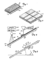
- Figure 1 is a fragmentary perspective view of a composite waterproofing sheet made according to the present invention;
- Figure 2 is a perspective view of a typical wall showing the composite waterproofing sheets made according to the present invention formed into individual panels in place, with overlapping seam edges to illustrate the multiple panels installed on a large wall;
- Figure 3 is a schematic representation of a machine for manufacturing composite waterproofing sheets made according to the present invention;
- Figure 4 is an enlarged view showing one bentonite application stations, shown in Figure 3, and illustrating the method of vibrating a conveyor belt in order to obtain a uniform layer of bentonite particles;
- Figure 5 is a force vector representation of the bentonite particle paths in relation to the forces applied to the belt by the beater; and
- Figure 6 is a schematic representation of apparatus for applying tension into a membrane to stretch it before adhesive is applied, which can be used as an introductory station to aid in insuring that the adhesive wall adhere to polyethylene for example.
- Figure 1 illustrates a finished composite
waterproofing sheet product 12, made according to the present invention and comprises amembrane 10 of material that is impervious to water, such as high density polyethylene, and a thickness or waterproofing layer of bentonite or sodium montmorillonite indicated at 11. - It is to be understood that the
layer 11 is meant to indicate a finished thickness of bentonite made up of a number of layers, each having a thickness of an individual bentonite particle with interspersed adhesive layers, made into a sandwich typecomposite waterproofing sheet 10. - In manufacture, an
edge portion 13 of the membrane orsheet 10 may be left without thelayer 11 of particles, as shown in Figure 2, so that the sheets or panels can be lapped. The lappededge portion 13 in Figure 2 along a longitudinal edge, and if smaller panels such as 1.2 m (4ft.) by 1.2 m (4ft.) panels are used, anedge portion 14 of the membrane will be left uncoated along one end of the panel as well. In this way the panels (or long strips or sheets) can be lapped where they meet, for holding them together when initially installing them, and also to permit the seams to have a continuous impervious membrane layer facing out from the surface. It should be noted that the composite waterproofing sheets are installed with the water impervious membrane facing outwardly to the elements. - Thus the composite structure comprises a flexible water impervious membrane in sheet form having a layer of particles, for waterproofing, preferably bentonite particles, on the surface at a desired depth.
- Adhesives that provide proper holding action are also important. While the prior art shows various adhesives that will work with bentonite, bentonite is highly reactive to many monovalant, divalant and trivalant materials. Bentonite also may form a permanent association with numerous other elements and compounds, and such products should be avoided in making the composite waterproofing sheets so that the bentonite particles do not react and lose their desirable property of swelling when contacted by water. When reactions do occur, or association of the bentonite particles with other elements occur, the waterproofing capabilities are degraded, because the bentonite material does not have the ability to swell and waterproof. The choice of adhesive is carefully made for making the
composite waterproofing sheet 20, the adhesive has to have the ability to adhere the bentonite particles to a polyethylene or other water impervious membrane, and minimize the degradation of the waterproofing capabilities of the bentonite. Adhesive materials are available as emulsions with water, solutes, concentrates, hot melts and often in homo or copolymer status. Almost any adhesive originating from a solvent, emulsion with water, hot melt or water emulsified solid may be used, and the choice is determined by the ability to wet, its stickiness, the polar activity and the final adhesion performance. The choice is influenced by price, toxicity, availability, or environmental considerations as well. The addition of wetting agents, emulsifiers, dispersants and preservatives for latexes can cause deterioration of the bentonite's ability to waterproof or reseal, so use of products may be minimized. - Adhesion to high density polyethylene has been difficult, and a common procedure to enhance adhesion is to chemically disturb the surface of the polyethylene or polymer membrane just prior to the application of the adhesive, for example by treating it with ozone. This brings in time limitations which means that the membrane has to be coated quite quickly because the molecules that are affected by the treatment migrate back to their original smooth alignment relatively fast.
- The total thickness of the layers of bentonite particles is built up to in the range of 3.18 mm (1/8 inch) to 6.35 mm (1/4 inch) thick, and thus a method of continuously achieving a permanent adhesion to the polyethylene membrane is required. The surface of the polyethylene preferably is roughened, and as shown herein, it can be done by stretching the polyethylene to microscopically "craze" the surface of the polyethylene. The amount and the direction of the tension applied to the membrane is determined by the thickness of the membrane. Generally, tensioning the membrane to about 207 KNm-2 (30 Ibs per square inch) is acceptable for thicknesses of 0.051 mm to 0.508 mm (2 to 20 mils). The membrane used herein is most preferably in 'the range of 0.508 mm (20 mils), but the preferred range is 0.381 mm to 2.54 mm (15 to 100 mils) in thickness. As will be explained, tensioning can be done by passing the polyethylene membrane over rollers which apply a stretch between pinch drive rollers.
- The adhesive used must wet the polyethylene surface for good adhesion, and low surface tension solvent systems provide a suitable vehicle to carry the adhesive.
- Aliphatics, aldehydes, ketones, carbon/halide and ring compounds all have utilization. Common carriers/solvents include toluene, lower molecular weight alcohols, methyl ketone and water. For example, the following products act as suitable adhesives:
- Asphalts (with or without fillers and elastomers)
- Butylenes
- Butyl Rubber
- Acrylics
- Propenes
- Styrene/butadiene
- Nitriles
- Vinyls
- Water Soluble:
- Cellulosics
- Saccharides
- Gums
- Proteins.
- In general, the adhesive solids should be present in concentrations from about 5 to 100% by weight, and are mixed with bentonite in ratios of between 3 and 50% by weight of the adhesive relative to the particles (bentonite).
- Referring specifically to Figure 6, the method of prestretching the polyethylene for applying the adhesive is illustrated schematically, and is a conventional method for stretching sheets of materials. The structure shown therein can constitute the polyethylene supply of the main machine which will be discussed. A roll of polyethylene membrane material or other suitable sheet material is indicated at 20, and the membrane is passed through a pair of
pinch rollers 21, which are driven from amotor 21A at a first speed and clamp the polyethylene membrane so it is driven at this set rate. The polyethylene is then run over suitable tensioning rollers indicated generally at 22 and 23 (more tensioning rollers may be used), and then the membrane is passed through a pair ofpinch drive rollers 26. Thedrive rollers 26 are also driven by asuitable motor 26A, and tension can be applied to the membrane by driving therollers 26 at a different (faster) lineal speed than therollers 21. The membrane will be tensioned because of the differential in speed. - Another way of stretching the membrane would be to run a section of sheet material between the first and second sets of pinch rollers, and then move the rollers, or guide
rollers 22 and 23, in opposite directions (indicated by arrows) to stretch the membrane 10 a desired amount, and then subsequently run an additional length of material onto the stretching idler rollers. However, in a continuous process, the method of tensioning or stretching the polyethylene membrane (or other membrane) can be used applying known principles, and thus the showing is done only schematically herein. Additionally, treated polyethylene can be obtained that has the ozone treatment previously mentioned. - Figure 3 illustrates schematically the method of applying adhesive and particles to the water impervious membrane. The material supply indicated generally at 30, which can comprise a roll, if the membrane is treated, or the stretching rollers and drive shown in Figure 6, provides a continuous sheet of the
membrane 10 that passes over aguide roller 31, and then is fed onto the top of conveyor belt assembly indicated generally at 32 having anendless belt 32A. As shown, the conveyor belt assembly is schematically represented as having adrive roller 33 at its upper end, and anidler roller 34 at its lower end over which thebelt 32A is mounted. Theconveyor belt 32A and thus themembrane sheet 10 are inclined in the range of 20° to 50° with respect to a horizontal plane. The conveyor belt incline is matched with a downwardly extendingconveyor section 38 thay may be rollers or a conveyor belt and which is shown only partially, on which themembrane sheet 10 will run after the particles have been applied to form thecomposite waterproofing sheet 12. The downward incline is to insure that themembrane 10 will be carried upwardly by theconveyor belt 32A because there will be a downward component of loading tending to keep themembrane 10 moving upwardly on the incline. There will be some friction between the conveyor and the undersurface of the membrane as well. If needed, drive rollers can be utilized. The conveyor belt can be open mesh, a runner coated belt or any desired construction. - The
membrane sheet 10 has a surface that faces upwardly and as it is carried up the incline, themembrane 10 passes through a first particle application station indicated generally at 35, a second station indicated generally at 36, and a third station indicated generally at 37. More application stations are generally used, but the stations illustrated show the method. Eachstation adhesive supply 40 feeding an adhesive through a feed control 40A to aspray bar 41 that extends transversely across the width of themembrane sheet 10. If the membrane is in the range of 1.2 m (4 feet) wide, the adhesive bar would be that long. Known adhesive spray bars can be utilized. The adhesive used can be selected from the group previously listed, and as shown by the dotted line representations at 42, the adhesive is sprayed in a thin layer onto the moving membrane in a first processing region indicated generally at 43. Thecoated membrane 10 moves upwardly a distance on the inclined conveyor, and a second portion of thestaton 35, comprising abentonite hopper 46 having a transversely extendingfeed section 47 of conventional design also controlled as to rate of feed with a conventional rate offeed control 49 applies a uniform, relatively thin line of bentonite particles indicated at 48 across the membrane. The bentonite particles drop onto the conveyor, immediately above or in the vicinity of arotating beater bar 52 that is mounted in a suitable manner on bearings at opposite ends and is driven from amotor 53 to rotate at a desired speed. The beater bars 52 has two radial longitudinal extendinglugs 54 on opposite sides thereof (diametrically opposed). Two positions of the lugs are shown in Figures 4 and 5, one in dotted lines. Thelugs 54 strike the conveyor belt on its undersurface and vibrate it upwardly to bounce the bentonite particles upwardly from the belt and the membrane (at least particles that have not initially adhered to the layer of adhesive) and the loose particles then will tend to fall back into the region shown at 55 in Figure 3. A type of "standing wave" of individual particles is created because they will tend to fall back onto the membrane and be replaced by new particles bounced in the air by the beater bar. The particles which have touched the adhesive move upwardly with the membrane, but are locked in place. - This low frequency, vertical vibrating action dislodges non-adhered bentonite particles, and insures that a totally adhered, uniform single particle thick layer is applied to the first adhesive layer in
station 35. - As the
conveyor belt 32A andmembrane sheet 10 move through thesecond station 36, the layering action is repeated. Thesecond sprayer bar 41 applies a thin layer of adhesive in a region shown at 57, which would be applied on the upper surface of the first layer of bentonite particles, as well as flowing slightly in between any spaces in the bentonite particles forming the first layer. The rate of feed of adhesive can be controlled with feed control 40A. As Asecond bentonite hopper 46 with afeed assembly 47 and rate offeed control 49 will apply another individual particle layer onto the first layer of particles and the second layer of adhesive applied in theregion 57. Thehopper 46 at thesecond station 36 is also immediately above abeater bar 52 that is driven from amotor 53 as well. This beater bar acts as before and forms a second standing wave or particles to cause a second, single particle thick layer of particles to form on top of the first layer of particles, so that now there are two layers of particles adhered to the upper surface of themembrane 10. - In the
third station 37, the same action occurs, and here the adhesive is applied in a section 60 of the membrane. A third layer of adhesive is applied in section 60 with athird spray bar 41, and when the applied thin layer of adhesive is moved up under the thirdstation bentonite hopper 46, the feed of particles from thefeed section 47 of thethird station 37 falls down onto the new or fresh adhesive layer to form a third layer of particles on the membrane. The particles are deposited above athird beater bar 52 driven from amotor 53 to form astanding wave 55 atstation 37, forming the uniform, single particle depth layer of material. - The number of layers of particle material desired, to achieve the desired thickness determines the number of individual stations that are utilized. This process may be used for forming adhering layers of particles to membranes or sheets for various uses, such as single layer sandpaper or non-slip pads, as well as for waterproofing sheets.
- Figure 4 illustrates in greater detail the individual layers of particles indicated at 61, 62 and 63, which would be applied after the adhesive station in the region 60 of the membrane. The conveyor belt movement direction is indicated by the
arrow 65, and it can be seen that the beater bar forms a standing wave section shown at 66 where the particles tend to make a loop, and the particles that are falling rearwardly will fall down onto the adhesive from the spray bar that applies the adhesive in the area 60 and to retain a single particle thick layer. The adhesive layer is controlled in thickness to accomplish this purpose. - Figure 5 illustrates the forces and the amplitude of movement caused by the
beater 54. The conveyor belt and membrane deflect upwardly as shown in dotted lines at 70, tending to throw or project the particles upwardly from the belt as shown by thearrow 71. The particles then fall under gravity generally downwardly, at the same time the conveyor belt and membrane are moving upwardly in the direction as indicated by thearrow 65, so that the adhesive coated particles indicated generally at 72, with the fresh layer of adhesive on top will collect the next layer of particles to form the uniform depth layers. - The upward force vector is shown by the
vertical arrow 71, gravity is shown by the arrow 75, and the invididual particle indicated at 76 is falling in direction along the arrow 75 as a direction of return. A standing wave again is shown generally at 66 where the particles tend to loop over and adhere to the adhesive. - The sequence is applying adhesive, and a uniform single particle thick layer across the surface of the membrane sheet of material (leaving an edge portion for the lap seam shown in Figure 2) and then applying a uniform layer of particles above a vibrator or beater, so that the particles adhere as the material is moved in an upwardly inclined plane. Additional layers are added at additional, individual stations positioned in sequence along the inclined membrane.
- Nonadhering particles are problems in an adhesive layer, and in the present device, non- adhering particles would act as a bond breaker, or separation with subsequent layers. Such condition (non-adhering particles) causes delamination and separation which leaves the waterproofing sheet unsuitable for use. It could not be transported, handled for installation, nor provide proper waterproofing qualities. The method described, using the beaters, insures that every particle is tested to insure it is fully adhered to the adhesive before a new layer is added. The apparatus performs in situ testing of the particle 'bonds.
- Large particles applied in a single layer and premixing the adhesive with the particles does not form a uniform thickness, leaves voids and spaces, and separates when folded around outside corners of a structure. Another way of attempting to add particles to a membrane has been to wet the membrane with adhesive and then pull it through a supply of particles. This wipes off adhesive and generally is unsatisfactory.
- The present process shown utilizes a minimum amount of adhesive, with a controlled ratio of adhesive to particles. Because a fresh layer of adhesive is applied at each station, dry areas are prevented and a uniform thickness is achieved. Particle size of bentonite can range up to 0.105 mm (150 mesh, using standard mesh sizes) for bentonite. The beater tends to cause the unattached particles to become airborne, and the loose particles will continue to be forced back into the adhesive to form the standing wave explained.
- The ratios of adhesive to particles is easily controlled by the size of the nozzles, pressure and the spray bar, as well as the rate of feed of the particles. 8.9 N to 53.4 N (two to 12 pounds) of adhesive to 178.0 N (40 pounds) of particles is a range that is generally satisfactory, and it should be pointed out that if too much adhesive is used, it will tend to flow downwardly and not be carried up the incline. The dry particles are kept airborne by the beaters, so that they will not pass through the station until they have lodged in adhesive and adhere in a desired layer.
- The particle size can be between 4 mm and 0.297 mm (5 and 150 mesh using standard U.S. standard mesh sizes). If desired, air entraining of particles (fluidizing) can be used for feeding the particles. Lowering the amplitude and frequency of the beater bar at the final station will cause the production of a dry particle coating over the entire layer, which would tend to have a little less adherence, but it would be an immediate physical state for packaging. The beater bars generally in the final station would have an amplitude of about 3.175 mm (1/8 of an inch) with a frequency of about 100 rpm (200 beats per minute). The amplitude of the "beat" is limited by the force of gravity, i.e. how fast does the conveyor belt resume its original position before being "hit" again by the rotating beater.
- In the other stations, the amplitude of the beater bar and the rotational velocity of the beater in relation to linear velocity of the conveyor belt is selected to be proper for the angle of inclination of the conveyor belt. For example, an amplitude of the beater of a 3.175 mm (1/8 inch) rotating at 180 rpm, when the velocity of the conveyor belt is approximately 0.127 ms-1 (25 feet per minute) with an angle of incline of 30° results in the bentonite particles being knocked back about 50.8 mm (two inches) so that the standing wave develops in an area of the membrane about two inches behind the beater bar. The particles returning from the area of beating, plus the newly supplied particles provide the uniform coating that sticks to the adhesive. The coating or composite layer of bentonite preferably ranges between 35.9 and 47.9 Nm-2 (.75 pound and one pound per square foot) for adequate waterproofing capabilities.
- The coating or composite layer of bentonite is built up to a weight of about one pound per square foot for adequate waterproofing characteristics for the
composite waterproofing sheet 12. - A part of final sizing,
compression rollers frame 81 and driven with amotor 82 at a desired speed, synchronized with the membrane speed of movement. Therollers 80 extend across the composite sheet and compress the membrane layers of bentonite particles together to provide a uniform depth layer and to force the particles to be sealed in adhesive. - Water soluble (misable) colorants may be added to the bentonite layer. When present, these colorants dissolve in the water and make a stain when wate leaks through any damage such as a rip or tear in the
non-permeable membrane 10, thus clearly marking the size, location and origin of the leaking water. - This capacity is especially valuable on horizontal surfaces such as roofs, decks, plazas, etc. This feature could not be used if the membrane were not impermeable to the passage of water.
- Common water misable or soluble dyes such as used in Easter eggs (non-staining) or tracing dyes which are used in extremely small quantities such as the ultraviolet fluoroescent family would also be suitable.
- The mechanical components and conveyors may be suitable, commercially available components and thus the spray bars, hoppers and rollers are shown only schematically.
- This invenion makes possible a waterproofing installation to the substrate under a floor prior to the concrete pour. It would be installed bentonite side facing the earth with each sheet overlapped along its edges as explained.
- Although the present invention has been described with reference to preferred embodiments, workers skilled in the art will recognize that changes may be made in form and detail without departing from the scope of the claims.
Claims (14)
Priority Applications (1)
| Application Number | Priority Date | Filing Date | Title |
|---|---|---|---|
| AT86907191T ATE60722T1 (en) | 1985-11-22 | 1986-11-20 | WATER DAM. |
Applications Claiming Priority (2)
| Application Number | Priority Date | Filing Date | Title |
|---|---|---|---|
| US06/801,007 US4693923A (en) | 1985-11-22 | 1985-11-22 | Water barrier |
| US801007 | 1997-02-19 |
Publications (3)
| Publication Number | Publication Date |
|---|---|
| EP0246311A1 EP0246311A1 (en) | 1987-11-25 |
| EP0246311A4 EP0246311A4 (en) | 1988-04-18 |
| EP0246311B1 true EP0246311B1 (en) | 1991-02-06 |
Family
ID=25179945
Family Applications (1)
| Application Number | Title | Priority Date | Filing Date |
|---|---|---|---|
| EP19860907191 Expired - Lifetime EP0246311B1 (en) | 1985-11-22 | 1986-11-20 | Water barrier |
Country Status (7)
| Country | Link |
|---|---|
| US (1) | US4693923A (en) |
| EP (1) | EP0246311B1 (en) |
| JP (3) | JPS63501413A (en) |
| AU (1) | AU6732387A (en) |
| CA (1) | CA1260331A (en) |
| HK (1) | HK39494A (en) |
| WO (1) | WO1987003225A1 (en) |
Cited By (2)
| Publication number | Priority date | Publication date | Assignee | Title |
|---|---|---|---|---|
| EP0714965A1 (en) | 1994-12-02 | 1996-06-05 | BBZ INJEKTIONS- UND ABDICHTUNGSTECHNIK GmbH | Sealing material from renewable resources |
| US6537676B1 (en) | 1992-08-26 | 2003-03-25 | Rawell Group Holdings Limited | Waterproofing material and method of fabrication therefor |
Families Citing this family (49)
| Publication number | Priority date | Publication date | Assignee | Title |
|---|---|---|---|---|
| US5079088A (en) * | 1985-11-22 | 1992-01-07 | Paramount Technical Products, Inc. | Water barrier |
| FR2619584B1 (en) * | 1987-08-17 | 1989-12-01 | Jacob Christian | FLOOR COVERAGE AGAINST SOIL VEGETATION |
| US4837085A (en) * | 1987-12-15 | 1989-06-06 | Mcgroarty Bryan M | Joint leak stop membrane |
| WO1990014222A1 (en) * | 1989-05-18 | 1990-11-29 | Paramount Technical Products Inc. | Leakproofing for hazardous waste |
| US5091234A (en) * | 1989-06-30 | 1992-02-25 | Mcgroarty Bryan M | Composite water barrier sheet |
| US5112665A (en) * | 1990-02-15 | 1992-05-12 | American Colloid Company | Water barrier of water-swellable clay sandwiched between interconnected layers of flexible fabric |
| US4996812B1 (en) * | 1990-02-20 | 1999-11-02 | Carlisle Corp | Method of membrane application in roof construction |
| US5175965A (en) * | 1990-12-24 | 1993-01-05 | Sandra L. Miller | Method for forming sandpaper disks |
| US5158803A (en) * | 1991-06-17 | 1992-10-27 | William Haas | Emergency flat roof repair method |
| WO1993002807A1 (en) * | 1991-08-08 | 1993-02-18 | Paramount Technical Products Inc. | Laminated waterstop using bentonite and bentones |
| US5226279A (en) * | 1992-03-09 | 1993-07-13 | Rendon Herrero Oswald | Sealing method for the treatment of portland cement concrete |
| FR2690688B1 (en) * | 1992-04-30 | 1994-07-22 | Isoform | PROCESS FOR DEPOSITING A LATEX COATING ON AN ELASTOMERIC PART AND A COMPOSITE PART BASED ON SILICONE ELASTOMER COMPRISING A LATEX COATING. |
| US5380552A (en) * | 1992-08-24 | 1995-01-10 | Minnesota Mining And Manufacturing Company | Method of improving adhesion between roofing granules and asphalt-based roofing materials |
| SG50604A1 (en) * | 1992-08-26 | 1998-07-20 | Rawell Group Holdings Ltd | Water proofing liner |
| WO1995027616A1 (en) * | 1994-04-07 | 1995-10-19 | Mcgroarty Bryan M | Resealable liner |
| FR2720764B1 (en) * | 1994-06-01 | 1996-08-23 | Lefebre Entr Jean | Two-layer waterproofing complex for a site and method for implementing such a waterproofing complex. |
| US5576065A (en) * | 1995-02-03 | 1996-11-19 | Poly Wall International, Inc. | Multilayered system for waterproofing rigid structural materials |
| US5663230A (en) * | 1995-02-15 | 1997-09-02 | Concrete Sealants, Inc. | Water stop composition and methods of preparing same |
| CA2242638A1 (en) * | 1995-10-24 | 1997-05-01 | Camelot Superabsorbents Limited | Absorbent articles |
| US5788413A (en) * | 1996-03-28 | 1998-08-04 | I-Corp International, Inc. | Geocomposite membrane |
| US6025032A (en) * | 1998-03-03 | 2000-02-15 | Poly Wall International, Inc. | Method and composition for waterproofing |
| US6224700B1 (en) | 1998-11-11 | 2001-05-01 | Mar-Flex Systems, Inc. | Methods for waterproofing architectural surfaces |
| US6426309B1 (en) | 1998-12-30 | 2002-07-30 | Owens Corning Fiberglas Technology, Inc. | Storm proof roofing material |
| US20040014385A1 (en) * | 1998-12-30 | 2004-01-22 | Greaves Gerald G. | Storm resistant roofing material |
| CA2336559A1 (en) * | 1999-05-04 | 2000-11-09 | John H. Gaveske | Method and composition for waterproofing |
| US6197398B1 (en) * | 1999-11-22 | 2001-03-06 | Gse Lining Technology, Inc. | Earthen liner with clay seam cover |
| CA2337973A1 (en) * | 2000-03-22 | 2001-09-22 | Illinois Tool Works Inc. | Weather resistant anti-slip panels |
| US6742313B2 (en) * | 2001-03-15 | 2004-06-01 | R.S. Associates, Inc. | Non-cellular adhesive for composite roof structure |
| US20020110668A1 (en) * | 2001-02-15 | 2002-08-15 | 3M Innovative Properties Company | Method of forming seamless article covering and articles formed thereby |
| US6679018B2 (en) * | 2002-02-01 | 2004-01-20 | Chem Link, Inc. | Roofing system and method |
| GB2389560B (en) | 2002-06-12 | 2005-04-13 | Rawell Group Holdings Ltd | Waterproofing material |
| US20040059036A1 (en) * | 2002-09-23 | 2004-03-25 | Gaveske John H. | Method and composition for waterproofing |
| US20060009100A1 (en) * | 2004-07-08 | 2006-01-12 | Mcgroarty Bryan | Waterproofing membrane |
| WO2007027224A2 (en) * | 2005-04-28 | 2007-03-08 | Monosol, Llc | Water-soluble composition and structures, and methods of making and using the same |
| USH2257H1 (en) * | 2005-09-28 | 2011-06-07 | The United States Of America As Represented By The Secretary Of The Navy | Microtags for detection and identification of materials |
| JP4644117B2 (en) * | 2005-12-28 | 2011-03-02 | 花王株式会社 | Powder and particle dispersion method and apparatus |
| DE502006003561D1 (en) * | 2006-12-19 | 2009-06-04 | Matthaei Bauunternehmen Gmbh & | Self-sealing waterproofing material for sealing floor surfaces |
| US10016954B2 (en) * | 2007-11-19 | 2018-07-10 | Amcol International Corporation | Self healing salt water barrier |
| US10012079B2 (en) * | 2007-11-19 | 2018-07-03 | Amcol International Corporation | Self healing salt water barrier |
| EP2177349A1 (en) * | 2008-10-15 | 2010-04-21 | Sika Technology AG | Waterproof membrane |
| WO2010088468A2 (en) * | 2009-01-30 | 2010-08-05 | Tegraseal Products, Llc | Water containment and exclusion products |
| US8318616B2 (en) * | 2009-08-19 | 2012-11-27 | Amcol International Corporation | Salt water swellable compositions and articles |
| JP5462645B2 (en) * | 2010-01-25 | 2014-04-02 | トヨタホーム株式会社 | Tarpaulin |
| EP2505719B1 (en) | 2011-03-31 | 2016-05-04 | Amcol International Corporation | Self healing salt water barrier |
| CN102518151A (en) * | 2011-11-26 | 2012-06-27 | 东南大学 | Soil engineering gasket suitable for environment containing multivalent cation mineral and preparation method thereof |
| US20140044956A1 (en) * | 2012-08-10 | 2014-02-13 | Tegraseal Products, Llc | Hydrophilic rubber composition |
| CN106540868B (en) * | 2016-12-12 | 2022-11-22 | 江西中材太阳能新材料有限公司 | Automatic sand planting equipment and automatic sand planting system |
| ES2908402T3 (en) * | 2017-09-05 | 2022-04-29 | Sika Tech Ag | Adhesive composition and use thereof to provide self-healing adhered roofing systems |
| US20210324241A1 (en) * | 2018-09-04 | 2021-10-21 | Sika Technology Ag | Adhesive composition and use thereof for enabling detection of leakages in fully-adhered roof systems |
Family Cites Families (23)
| Publication number | Priority date | Publication date | Assignee | Title |
|---|---|---|---|---|
| US2603575A (en) * | 1949-11-17 | 1952-07-15 | Jr August F Schramm | Method of making a stiffened permeable resin coated fibrous sheet |
| US3186896A (en) * | 1962-05-09 | 1965-06-01 | American Colloid Co | Moisture impervious panel |
| US3497409A (en) * | 1966-02-01 | 1970-02-24 | American Colloid Co | Method of forming a moisture impervious panel |
| US3466827A (en) * | 1967-01-10 | 1969-09-16 | American Colloid Co | Moisture impervious deck construction |
| DE2006854A1 (en) * | 1970-02-14 | 1971-09-09 | Fa Josef Schmitter, 8725 Arnstein | Multi-layered thermoplastic packaging filmfo |
| US3676198A (en) * | 1970-05-11 | 1972-07-11 | Bryan M Mcgroarty | Method for waterproofing structures |
| US3949560A (en) * | 1973-02-07 | 1976-04-13 | American Colloid Company | Method and composition for preventing water contaminated with industrial waste from seeping through soil containing said water |
| US4021402A (en) * | 1974-05-23 | 1977-05-03 | American Colloid Company | Method and composition for preventing water contaminated with industrial waste seeping through soil containing said water |
| US4048373A (en) * | 1974-05-23 | 1977-09-13 | American Colloid Company | Water barrier panel |
| JPS5346612B2 (en) * | 1974-09-30 | 1978-12-15 | ||
| JPS5198120A (en) * | 1975-02-26 | 1976-08-28 | Bosuishiito oyobi gaishiitoomochiitakenzobutsunobosuikoho | |
| US4084382A (en) * | 1975-08-18 | 1978-04-18 | American Colloid Company | Method and composition for preventing water contaminated with industrial waste seeping through soil containing said water |
| PH13790A (en) * | 1975-10-28 | 1980-10-01 | American Colloid Co | Water barrier panel and method |
| US4070839A (en) * | 1976-09-09 | 1978-01-31 | American Colloid Company | Moisture impervious panel |
| US4126543A (en) * | 1977-02-14 | 1978-11-21 | American Colloid Company | Method and apparatus for screening particulate materials |
| US4139588A (en) * | 1977-05-25 | 1979-02-13 | American Colloid Company | Method of making a water barrier panel |
| US4209568A (en) * | 1978-09-18 | 1980-06-24 | American Colloid Company | Bentonite-gelled oil waterproofing composition |
| US4212691A (en) * | 1978-11-21 | 1980-07-15 | Congoleum Corporation | Methods and apparatus for making decorative inlaid types of resilient sheet materials and the like |
| JPS5824439A (en) * | 1981-08-05 | 1983-02-14 | 平岡織染株式会社 | Non-dew condensation waterproof sheet and its manufacture |
| US4467015A (en) * | 1981-11-02 | 1984-08-21 | Clem Arthur G | Waterproofing structure |
| US4534926A (en) * | 1982-11-22 | 1985-08-13 | American Colloid Company | Uninhibited bentonite composition |
| US4581864A (en) * | 1983-05-26 | 1986-04-15 | Lidia Shvakhman | Waterproofing unit |
| DE3400079A1 (en) * | 1984-01-03 | 1985-07-11 | Röhm GmbH, 6100 Darmstadt | WATER-SPREADING PLASTIC MATERIAL, METHOD FOR THE PRODUCTION THEREOF AND USE AS GLAZING AND ROOFING MATERIAL |
-
1985
- 1985-11-22 US US06/801,007 patent/US4693923A/en not_active Expired - Lifetime
-
1986
- 1986-11-20 JP JP61506163A patent/JPS63501413A/en active Pending
- 1986-11-20 WO PCT/US1986/002472 patent/WO1987003225A1/en active IP Right Grant
- 1986-11-20 AU AU67323/87A patent/AU6732387A/en not_active Abandoned
- 1986-11-20 EP EP19860907191 patent/EP0246311B1/en not_active Expired - Lifetime
- 1986-11-21 CA CA000523582A patent/CA1260331A/en not_active Expired
-
1994
- 1994-04-28 HK HK39494A patent/HK39494A/en not_active IP Right Cessation
-
1996
- 1996-07-08 JP JP1996006488U patent/JP2568050Y2/en not_active Expired - Lifetime
- 1996-08-07 JP JP1996007834U patent/JP2584238Y2/en not_active Expired - Lifetime
Cited By (2)
| Publication number | Priority date | Publication date | Assignee | Title |
|---|---|---|---|---|
| US6537676B1 (en) | 1992-08-26 | 2003-03-25 | Rawell Group Holdings Limited | Waterproofing material and method of fabrication therefor |
| EP0714965A1 (en) | 1994-12-02 | 1996-06-05 | BBZ INJEKTIONS- UND ABDICHTUNGSTECHNIK GmbH | Sealing material from renewable resources |
Also Published As
| Publication number | Publication date |
|---|---|
| HK39494A (en) | 1994-05-06 |
| JPH0926U (en) | 1997-01-17 |
| JP2584238Y2 (en) | 1998-10-30 |
| EP0246311A4 (en) | 1988-04-18 |
| CA1260331A (en) | 1989-09-26 |
| US4693923A (en) | 1987-09-15 |
| JP2568050Y2 (en) | 1998-04-08 |
| AU6732387A (en) | 1987-07-01 |
| JPH09304U (en) | 1997-05-27 |
| JPS63501413A (en) | 1988-06-02 |
| WO1987003225A1 (en) | 1987-06-04 |
| EP0246311A1 (en) | 1987-11-25 |
Similar Documents
| Publication | Publication Date | Title |
|---|---|---|
| EP0246311B1 (en) | Water barrier | |
| US5079088A (en) | Water barrier | |
| CA1174024A (en) | Method of waterproofing roofs and the like | |
| US9821532B2 (en) | Peel and stick waterproofing material | |
| US9909317B2 (en) | Roofing systems and methods | |
| US4172830A (en) | Waterproofing structure and method of using same | |
| US6878321B2 (en) | Method of manufacture of glass reinforced gypsum board and apparatus therefor | |
| EP1866497B1 (en) | Exterior sheathing weather barrier construction and method of manufacture | |
| US20140260074A1 (en) | Roofing systems and methods | |
| US4965119A (en) | Tapered roofing tape | |
| US20060052016A1 (en) | Non-cellular adhesive for composite roof structure | |
| US4910059A (en) | Tapered roofing membrane | |
| US4837085A (en) | Joint leak stop membrane | |
| EP1767697B1 (en) | Flooring material, methods for producing and laying same | |
| AU2003277055B2 (en) | Waterproofing material | |
| RU2112848C1 (en) | Construction of roofing primarily from polymeric material reinforced with fabric | |
| JPH04296544A (en) | Jointing method of water-barrier sheet | |
| MXPA01005711A (en) | Storm proof roofing material | |
| CZ302480B6 (en) | Process for the manufacture of a bituminous coating sheet and such a coating sheet produced in such a manner | |
| JPH04296532A (en) | Method for bonding water-barrier sheet | |
| CA2038576A1 (en) | Torchable roofing base sheet | |
| JP2000008555A (en) | Water-resistant sheet with embossment and water- resistant method thereof |
Legal Events
| Date | Code | Title | Description |
|---|---|---|---|
| PUAI | Public reference made under article 153(3) epc to a published international application that has entered the european phase |
Free format text: ORIGINAL CODE: 0009012 |
|
| 17P | Request for examination filed |
Effective date: 19870722 |
|
| AK | Designated contracting states |
Kind code of ref document: A1 Designated state(s): AT BE CH DE FR GB LI |
|
| A4 | Supplementary search report drawn up and despatched |
Effective date: 19880418 |
|
| 17Q | First examination report despatched |
Effective date: 19890407 |
|
| GRAA | (expected) grant |
Free format text: ORIGINAL CODE: 0009210 |
|
| AK | Designated contracting states |
Kind code of ref document: B1 Designated state(s): AT BE CH DE FR GB LI |
|
| REF | Corresponds to: |
Ref document number: 60722 Country of ref document: AT Date of ref document: 19910215 Kind code of ref document: T |
|
| REF | Corresponds to: |
Ref document number: 3677504 Country of ref document: DE Date of ref document: 19910314 |
|
| ET | Fr: translation filed | ||
| PLBE | No opposition filed within time limit |
Free format text: ORIGINAL CODE: 0009261 |
|
| STAA | Information on the status of an ep patent application or granted ep patent |
Free format text: STATUS: NO OPPOSITION FILED WITHIN TIME LIMIT |
|
| 26N | No opposition filed | ||
| REG | Reference to a national code |
Ref country code: GB Ref legal event code: IF02 |
|
| PGFP | Annual fee paid to national office [announced via postgrant information from national office to epo] |
Ref country code: AT Payment date: 20051102 Year of fee payment: 20 |
|
| PGFP | Annual fee paid to national office [announced via postgrant information from national office to epo] |
Ref country code: GB Payment date: 20051116 Year of fee payment: 20 |
|
| PGFP | Annual fee paid to national office [announced via postgrant information from national office to epo] |
Ref country code: FR Payment date: 20051117 Year of fee payment: 20 |
|
| PGFP | Annual fee paid to national office [announced via postgrant information from national office to epo] |
Ref country code: CH Payment date: 20051125 Year of fee payment: 20 |
|
| PGFP | Annual fee paid to national office [announced via postgrant information from national office to epo] |
Ref country code: BE Payment date: 20051208 Year of fee payment: 20 |
|
| PGFP | Annual fee paid to national office [announced via postgrant information from national office to epo] |
Ref country code: DE Payment date: 20060102 Year of fee payment: 20 |
|
| PG25 | Lapsed in a contracting state [announced via postgrant information from national office to epo] |
Ref country code: GB Free format text: LAPSE BECAUSE OF EXPIRATION OF PROTECTION Effective date: 20061119 |
|
| REG | Reference to a national code |
Ref country code: GB Ref legal event code: PE20 |
|
| REG | Reference to a national code |
Ref country code: CH Ref legal event code: PL |
|
| BE20 | Be: patent expired |
Owner name: *MCGROARTY PATRICK J. Effective date: 20061120 Owner name: *MCGROARTY BRYAN M. Effective date: 20061120 |