EP0246213B1 - Automatische Öffnungs- und Schliessvorrichtung für Tore - Google Patents
Automatische Öffnungs- und Schliessvorrichtung für Tore Download PDFInfo
- Publication number
- EP0246213B1 EP0246213B1 EP87850153A EP87850153A EP0246213B1 EP 0246213 B1 EP0246213 B1 EP 0246213B1 EP 87850153 A EP87850153 A EP 87850153A EP 87850153 A EP87850153 A EP 87850153A EP 0246213 B1 EP0246213 B1 EP 0246213B1
- Authority
- EP
- European Patent Office
- Prior art keywords
- gate
- bolt
- kingpost
- cable
- pushbars
- Prior art date
- Legal status (The legal status is an assumption and is not a legal conclusion. Google has not performed a legal analysis and makes no representation as to the accuracy of the status listed.)
- Expired - Lifetime
Links
- 241001465754 Metazoa Species 0.000 claims description 6
- 238000013459 approach Methods 0.000 claims description 3
- 230000006835 compression Effects 0.000 claims description 3
- 238000007906 compression Methods 0.000 claims description 3
- 230000015572 biosynthetic process Effects 0.000 claims description 2
- 239000002184 metal Substances 0.000 abstract 1
- 230000000712 assembly Effects 0.000 description 2
- 238000000429 assembly Methods 0.000 description 2
- 230000005484 gravity Effects 0.000 description 2
- 238000010276 construction Methods 0.000 description 1
- 239000013536 elastomeric material Substances 0.000 description 1
- 238000012986 modification Methods 0.000 description 1
- 230000004048 modification Effects 0.000 description 1
- 238000003466 welding Methods 0.000 description 1
Images


Classifications
-
- A—HUMAN NECESSITIES
- A01—AGRICULTURE; FORESTRY; ANIMAL HUSBANDRY; HUNTING; TRAPPING; FISHING
- A01K—ANIMAL HUSBANDRY; AVICULTURE; APICULTURE; PISCICULTURE; FISHING; REARING OR BREEDING ANIMALS, NOT OTHERWISE PROVIDED FOR; NEW BREEDS OF ANIMALS
- A01K1/00—Housing animals; Equipment therefor
- A01K1/0005—Stable partitions
- A01K1/0017—Gates, doors
-
- E—FIXED CONSTRUCTIONS
- E05—LOCKS; KEYS; WINDOW OR DOOR FITTINGS; SAFES
- E05B—LOCKS; ACCESSORIES THEREFOR; HANDCUFFS
- E05B65/00—Locks or fastenings for special use
- E05B65/0007—Locks or fastenings for special use for gates
Definitions
- This invention relates to gates and more particularly to a device for opening and closing such a gate as, say, a farm gate.
- US-A-3,303,613 describes a farm gate with an automatic opening and closing device incorporating a kingpost fixed to and extending substantially vertically between an upper frame member and a lower frame member of said gate; a pair of pushbars being mounted on said kingpost for limited pivotal movement thereabout; a first pushbar disposed on one side of said gate and a second pushbar disposed on the other side of said gate; a spring-urged bolt located adjacent the free, outer frame member or end rail of said gate and adapted to maintain said gate closed when said bolt engages with a co-acting latch means in or on a gate post; and a cable extending between an arm of said pushbar and said bolt, so that when a positive inward movement is applied to a pushbar said cable acts to disengage said bolt from said latch means, to cause said gate to spring open, and when a force is completed or removed, a cable will restore said pushbars to an initial position of rest for moving said gate to a closed position to enable said bolt to engage with said latch means.
- the pushbars extend over the entire height of the gate and the latch controlling cable is provided just below the upper frame member, which both details provide a risk that the gate may be opened by an animal pushing against the upper part of the pushbar or moving its head below the upper frame member of the gate and thereby applying a force on said cable sufficient to disengage the bolt from the latch mechanism.
- an automatic gate opening and closing device comprises a kingpost fixedly attached to and extending substantially vertically between an upper frame member and a lower frame member of said gate; a pair of pushbars being mounted on said kingpost for limited pivotal movement thereabout; a first pushbar being disposed on one side of said gate and a second pushbar being disposed on the other side of said gate; a spring-urged bolt being located adjacent the free, outer frame member or end rail of said gate and adapted to maintain said gate closed when said bolt engages with a co-acting latch means in or on a gate post; and a cable extending between an arm of each pushbar and said bolt, so that when a positive inward movement is applied to a pushbar said cable acts to disengage said bolt from said latch means, to cause said gate to spring open, and when a force is completed or removed, a cable will restore said pushbars to an initial position of rest for moving said gate to a closed position to
- the kingpost is provided with a square-section sleeve fitting thereover; there being, secured to said sleeve, a pair of bases disposed at 90° to each other so that one base is disposed at each side of the gate; a substantially vertically extending arm is provided at the free end of each base and includes a rotating elastomeric covering; and an adjustable cable anchor pivotally attached to each base adjacent the kingpost.
- the latch means may include a body portion attachable to the gatepost and a spaced- apart pair of wings pivotally mounted thereon, each wing being able to be caused to pivot towards the other wing when struck by the bolt as the gate approaches the closed position but being unable to pivot in the opposite direction, thereby retaining the bolt in the rest position between the wings.
- one end of the bolt should extend through an end-rail of the gate, the other end of the bolt being supported in a bracket securable to the bottom rail of the gate; the bolt being able to be axially moved in a first direction when pulled back by said cable attached to a shackle on the bolt and, in a second direction, being able to be returned to the rest position under the influence of a compression spring surrounding the bolt between the end-rail and the bracket.
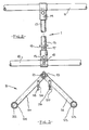
- arms 22 and 23 Upstanding from the free ends of bases 20 and 21 are arms 22 and 23, provided respectively with elastomeric sleeves 24 and 25. Pivotally attached to the arms, adjacent the kingpost, are adjustable cable anchors 26 and 27.
- FIGS 4 and 5 show a spring-loaded bolt assembly 3, attached to bottom rail 12 by a U-bolt 28 extending through a flanged plate 29.
- Spring-loaded bolt assembly 3 also includes a shaft 30, one end of which passes through a flange 31 of flanged plate 29 and terminates in a shackle 32 by a shackle-pin 33, and the other end of which passes through an end-rail 34 of the gate and is prevented from over- movement by bolt 35.
- a helical compression spring 36 surrounds shaft 30, held between flange 31 of the flanged plate, or bracket, 29 and a washer 37.
- a pair of cables, generally referenced 4 in Figure 1 extends between shackle 32 of the spring-loaded assembly and eye-bolts 38 and 39 of cable anchors 26 and 27. It will be appreciated from the foregoing that when pushbar assembly 2 is rotated about kingpost assembly pipe 13, one of the cables will operate so as to withdraw bolt shaft 30 from the latch means 5 on gatepost 9 to thus permit the gate to be swung open.
- the latch, or "two-way closer" means comprises a tubular body portion 41 attachable to the gatepost 9 by a pair of coach-screws 42, and a pair of wings 43 and 44 pivoting about bolts 45 and 46.
- the heads of coach-screws 42 also act as stops to prevent the lower portions of the wings from being swung outwardly.
- the inventive device operates in the following way:
- the gate begins to close under gravity.
- the protruding shaft pushes aside one of the pivoted wings but its swing is arrested by its coming into contact with the inner edge of the other wing.
- the shaft is arrested by the first wing which has since dropped back to a vertical position, thus fastening the gate without manual manipulation.
- the pushbars have a substantially "L" configuration, having bases and upstanding arms.
- the bases are shown as 20 and 21 and the upstanding vertical arms as 22 and 23 in Fig. 3 of the accompanying drawings.
- the upstanding arms 22 and 23 mount for free rotation thereabout, sleeves 24 and 25 which are preferably of an elastomeric material.
- the pushbars extend outwardly from each side of the gate and thus a freely rotatable sleeve is provided on each side of the gate.
- the pushbars and sleeves are positioned on the gate so as to be adjacent the bottom thereof.
- the motor vehicle When it is desired to open the gate, such as by using a motor vehicle, the motor vehicle is moved in against the arms of the pushbars and the sleeves and a positive forward movement is applied to the arms and sleeves which will to a certain extent compress the sleeves and move the sleeves and arms of the pushbars inwardly, and substantially arcuately towards the gate. This will in turn cause the ropes or wires to actuate the opening bolt and opening device.
- the latch means of the gate of the present invention is preferably mounted near the bottom bar of the gate so that the location is sufficiently low that an animal is unable to place its head under the bolt or locking bar.
Landscapes
- Life Sciences & Earth Sciences (AREA)
- Environmental Sciences (AREA)
- Zoology (AREA)
- Animal Husbandry (AREA)
- Biodiversity & Conservation Biology (AREA)
- Gates (AREA)
- Power-Operated Mechanisms For Wings (AREA)
- Vending Machines For Individual Products (AREA)
- Refuse Collection And Transfer (AREA)
- Closing And Opening Devices For Wings, And Checks For Wings (AREA)
Claims (4)
Priority Applications (1)
| Application Number | Priority Date | Filing Date | Title |
|---|---|---|---|
| AT87850153T ATE54014T1 (de) | 1986-05-09 | 1987-05-11 | Automatische oeffnungs- und schliessvorrichtung fuer tore. |
Applications Claiming Priority (2)
| Application Number | Priority Date | Filing Date | Title |
|---|---|---|---|
| AUPH581886 | 1986-05-09 | ||
| AU5818/86 | 1986-05-09 |
Publications (2)
| Publication Number | Publication Date |
|---|---|
| EP0246213A1 EP0246213A1 (de) | 1987-11-19 |
| EP0246213B1 true EP0246213B1 (de) | 1990-06-20 |
Family
ID=3771607
Family Applications (1)
| Application Number | Title | Priority Date | Filing Date |
|---|---|---|---|
| EP87850153A Expired - Lifetime EP0246213B1 (de) | 1986-05-09 | 1987-05-11 | Automatische Öffnungs- und Schliessvorrichtung für Tore |
Country Status (4)
| Country | Link |
|---|---|
| US (1) | US4870782A (de) |
| EP (1) | EP0246213B1 (de) |
| AT (1) | ATE54014T1 (de) |
| AU (1) | AU585446B2 (de) |
Families Citing this family (9)
| Publication number | Priority date | Publication date | Assignee | Title |
|---|---|---|---|---|
| AP386A (en) * | 1992-06-26 | 1995-07-28 | Jack Mishingo Thipe | The automatic safety gate units. |
| GB9302564D0 (en) * | 1993-02-10 | 1993-03-24 | Gulfdrive Limited | Barrier locking mechanism |
| US5390719A (en) * | 1993-08-10 | 1995-02-21 | Barnes; Michael S. | Canopy assembly pivotable by over-height vehicle |
| US20050212017A1 (en) * | 2004-03-29 | 2005-09-29 | Eugene Heisserer | Vehicle actuated gate apparatus |
| US7798544B1 (en) | 2006-09-27 | 2010-09-21 | Elwood Bates | Door and gate latch with horseshoe handle |
| EP2480066B1 (de) * | 2009-09-25 | 2015-05-13 | Cow-Welfare A/s | Verbesserter stallabteiler |
| US8690202B2 (en) * | 2012-08-09 | 2014-04-08 | Mark Lankford | Control mechanism |
| CN108999560A (zh) * | 2018-10-08 | 2018-12-14 | 丰和营造集团股份有限公司 | 一种免人工控制的车辆进出门 |
| US11619070B2 (en) | 2021-06-10 | 2023-04-04 | Dennis L. Bach | Corral gate latch release device |
Family Cites Families (8)
| Publication number | Priority date | Publication date | Assignee | Title |
|---|---|---|---|---|
| CA502165A (en) * | 1954-05-04 | Strom Ernest | Bump gate | |
| US1798096A (en) * | 1929-11-04 | 1931-03-24 | John H Mcdevitt | Gate |
| US2538470A (en) * | 1946-02-09 | 1951-01-16 | Louis H Peeples | Gate |
| US2718079A (en) * | 1950-09-07 | 1955-09-20 | Paul M Strey | Vehicle operated cushion mounted gate |
| US2786289A (en) * | 1954-04-07 | 1957-03-26 | William H Koch | Releasable gravity return gate |
| US2982036A (en) * | 1958-11-17 | 1961-05-02 | Carl J Piper | Vehicle actuated gate |
| AU5439365A (en) * | 1965-01-26 | 1967-05-11 | George Brotherson Kenneth | Automatic farm gate |
| US3303613A (en) * | 1965-02-04 | 1967-02-14 | Ronald P Seuntjens | Farm gate |
-
1987
- 1987-05-04 AU AU72486/87A patent/AU585446B2/en not_active Ceased
- 1987-05-08 US US07/047,329 patent/US4870782A/en not_active Expired - Lifetime
- 1987-05-11 EP EP87850153A patent/EP0246213B1/de not_active Expired - Lifetime
- 1987-05-11 AT AT87850153T patent/ATE54014T1/de not_active IP Right Cessation
Also Published As
| Publication number | Publication date |
|---|---|
| US4870782A (en) | 1989-10-03 |
| ATE54014T1 (de) | 1990-07-15 |
| AU585446B2 (en) | 1989-06-15 |
| AU7248687A (en) | 1987-11-12 |
| EP0246213A1 (de) | 1987-11-19 |
Similar Documents
| Publication | Publication Date | Title |
|---|---|---|
| US5018302A (en) | Burglar bar safety latch assembly | |
| US4872287A (en) | Latching mechanism for trolley-hung doors | |
| US4283882A (en) | Safety flush bolt entrance door system | |
| EP0246213B1 (de) | Automatische Öffnungs- und Schliessvorrichtung für Tore | |
| US4531325A (en) | Hinged vehicle gate arm | |
| US6145570A (en) | Locking system for sectional doors | |
| US4759577A (en) | Door security apparatus | |
| US6185867B1 (en) | Entrance control device for sequential displacement of a plurality of barriers | |
| US4666195A (en) | Door security apparatus | |
| US6192629B1 (en) | Two-way gate | |
| US7637541B2 (en) | Gate assembly | |
| US4495730A (en) | Automatic farm gate | |
| US4387916A (en) | Gate latch assembly | |
| US3389501A (en) | Combination gate hinge and automatic closer | |
| US5463984A (en) | One way animal gate | |
| US6425612B1 (en) | Gravity operated gate latch | |
| US3296741A (en) | Spring operated gate | |
| US4616444A (en) | Radio controlled gate opener | |
| CA2032002C (en) | Animal gate latch mechanism | |
| GB2404413A (en) | Gate assembly | |
| US20060038416A1 (en) | Gate assembly | |
| US3976315A (en) | Gate lock | |
| US5178097A (en) | Head gate for calf chutes | |
| US1253655A (en) | Gate-hinge. | |
| US2699005A (en) | Vehicle operated, transverse horizontally pivoted gate |
Legal Events
| Date | Code | Title | Description |
|---|---|---|---|
| PUAI | Public reference made under article 153(3) epc to a published international application that has entered the european phase |
Free format text: ORIGINAL CODE: 0009012 |
|
| AK | Designated contracting states |
Kind code of ref document: A1 Designated state(s): AT BE CH DE ES FR GB GR IT LI LU NL SE |
|
| 17P | Request for examination filed |
Effective date: 19880519 |
|
| 17Q | First examination report despatched |
Effective date: 19890530 |
|
| GRAA | (expected) grant |
Free format text: ORIGINAL CODE: 0009210 |
|
| AK | Designated contracting states |
Kind code of ref document: B1 Designated state(s): AT BE CH DE ES FR GB GR IT LI LU NL SE |
|
| PG25 | Lapsed in a contracting state [announced via postgrant information from national office to epo] |
Ref country code: GR Free format text: LAPSE BECAUSE OF FAILURE TO SUBMIT A TRANSLATION OF THE DESCRIPTION OR TO PAY THE FEE WITHIN THE PRESCRIBED TIME-LIMIT Effective date: 19900620 Ref country code: NL Effective date: 19900620 Ref country code: IT Free format text: LAPSE BECAUSE OF FAILURE TO SUBMIT A TRANSLATION OF THE DESCRIPTION OR TO PAY THE FEE WITHIN THE PRE;WARNING: LAPSES OF ITALIAN PATENTS WITH EFFECTIVE DATE BEFORE 2007 MAY HAVE OCCURRED AT ANY TIME BEFORE 2007. THE CORRECT EFFECTIVE DATE MAY BE DIFFERENT FROM THE ONE RECORDED.SCRIBED TIME-LIMIT Effective date: 19900620 Ref country code: SE Effective date: 19900620 Ref country code: LI Effective date: 19900620 Ref country code: CH Effective date: 19900620 |
|
| REF | Corresponds to: |
Ref document number: 54014 Country of ref document: AT Date of ref document: 19900715 Kind code of ref document: T |
|
| REF | Corresponds to: |
Ref document number: 3763326 Country of ref document: DE Date of ref document: 19900726 |
|
| REG | Reference to a national code |
Ref country code: CH Ref legal event code: PL |
|
| PG25 | Lapsed in a contracting state [announced via postgrant information from national office to epo] |
Ref country code: ES Free format text: LAPSE BECAUSE OF FAILURE TO SUBMIT A TRANSLATION OF THE DESCRIPTION OR TO PAY THE FEE WITHIN THE PRESCRIBED TIME-LIMIT Effective date: 19901001 |
|
| ET | Fr: translation filed | ||
| NLV1 | Nl: lapsed or annulled due to failure to fulfill the requirements of art. 29p and 29m of the patents act | ||
| PLBE | No opposition filed within time limit |
Free format text: ORIGINAL CODE: 0009261 |
|
| STAA | Information on the status of an ep patent application or granted ep patent |
Free format text: STATUS: NO OPPOSITION FILED WITHIN TIME LIMIT |
|
| PG25 | Lapsed in a contracting state [announced via postgrant information from national office to epo] |
Ref country code: LU Free format text: LAPSE BECAUSE OF NON-PAYMENT OF DUE FEES Effective date: 19910531 |
|
| 26N | No opposition filed | ||
| PGFP | Annual fee paid to national office [announced via postgrant information from national office to epo] |
Ref country code: AT Payment date: 19920507 Year of fee payment: 6 |
|
| PGFP | Annual fee paid to national office [announced via postgrant information from national office to epo] |
Ref country code: BE Payment date: 19920513 Year of fee payment: 6 Ref country code: FR Payment date: 19920513 Year of fee payment: 6 |
|
| PGFP | Annual fee paid to national office [announced via postgrant information from national office to epo] |
Ref country code: DE Payment date: 19920721 Year of fee payment: 6 |
|
| PGFP | Annual fee paid to national office [announced via postgrant information from national office to epo] |
Ref country code: GB Payment date: 19930510 Year of fee payment: 7 |
|
| PG25 | Lapsed in a contracting state [announced via postgrant information from national office to epo] |
Ref country code: AT Effective date: 19930511 |
|
| PG25 | Lapsed in a contracting state [announced via postgrant information from national office to epo] |
Ref country code: BE Effective date: 19930531 |
|
| BERE | Be: lapsed |
Owner name: PURVES MURRAY Effective date: 19930531 |
|
| PG25 | Lapsed in a contracting state [announced via postgrant information from national office to epo] |
Ref country code: FR Effective date: 19940131 |
|
| PG25 | Lapsed in a contracting state [announced via postgrant information from national office to epo] |
Ref country code: DE Effective date: 19940201 |
|
| REG | Reference to a national code |
Ref country code: FR Ref legal event code: ST |
|
| PG25 | Lapsed in a contracting state [announced via postgrant information from national office to epo] |
Ref country code: GB Effective date: 19940511 |
|
| GBPC | Gb: european patent ceased through non-payment of renewal fee |
Effective date: 19940511 |