EP0245865B1 - Method to put an anchor bolt into a drilled hole of a foundation, and an anchor bolt for this method - Google Patents
Method to put an anchor bolt into a drilled hole of a foundation, and an anchor bolt for this method Download PDFInfo
- Publication number
- EP0245865B1 EP0245865B1 EP87107025A EP87107025A EP0245865B1 EP 0245865 B1 EP0245865 B1 EP 0245865B1 EP 87107025 A EP87107025 A EP 87107025A EP 87107025 A EP87107025 A EP 87107025A EP 0245865 B1 EP0245865 B1 EP 0245865B1
- Authority
- EP
- European Patent Office
- Prior art keywords
- expansion sleeve
- shank
- anchor bolt
- shaft
- expansion
- Prior art date
- Legal status (The legal status is an assumption and is not a legal conclusion. Google has not performed a legal analysis and makes no representation as to the accuracy of the status listed.)
- Expired
Links
- 238000000034 method Methods 0.000 title claims description 46
- 238000005520 cutting process Methods 0.000 claims description 23
- 239000011295 pitch Substances 0.000 claims description 6
- 230000000295 complement effect Effects 0.000 claims description 5
- 239000002184 metal Substances 0.000 claims description 2
- 230000002093 peripheral effect Effects 0.000 claims 12
- 238000006073 displacement reaction Methods 0.000 claims 3
- 230000000630 rising effect Effects 0.000 claims 3
- 230000007423 decrease Effects 0.000 claims 1
- 230000000452 restraining effect Effects 0.000 claims 1
- 230000008569 process Effects 0.000 description 15
- 239000004570 mortar (masonry) Substances 0.000 description 7
- 238000004873 anchoring Methods 0.000 description 5
- 239000000463 material Substances 0.000 description 3
- 230000007480 spreading Effects 0.000 description 3
- 238000003892 spreading Methods 0.000 description 3
- 239000002131 composite material Substances 0.000 description 2
- 230000000694 effects Effects 0.000 description 2
- 238000005299 abrasion Methods 0.000 description 1
- 230000009471 action Effects 0.000 description 1
- 230000008901 benefit Effects 0.000 description 1
- 230000015572 biosynthetic process Effects 0.000 description 1
- 230000008859 change Effects 0.000 description 1
- 150000001875 compounds Chemical class 0.000 description 1
- 230000008878 coupling Effects 0.000 description 1
- 238000010168 coupling process Methods 0.000 description 1
- 238000005859 coupling reaction Methods 0.000 description 1
- 238000005336 cracking Methods 0.000 description 1
- 238000009826 distribution Methods 0.000 description 1
- 238000000605 extraction Methods 0.000 description 1
- 238000003780 insertion Methods 0.000 description 1
- 230000037431 insertion Effects 0.000 description 1
- 230000014759 maintenance of location Effects 0.000 description 1
- 238000004519 manufacturing process Methods 0.000 description 1
- 230000007704 transition Effects 0.000 description 1
Images


Classifications
-
- F—MECHANICAL ENGINEERING; LIGHTING; HEATING; WEAPONS; BLASTING
- F16—ENGINEERING ELEMENTS AND UNITS; GENERAL MEASURES FOR PRODUCING AND MAINTAINING EFFECTIVE FUNCTIONING OF MACHINES OR INSTALLATIONS; THERMAL INSULATION IN GENERAL
- F16B—DEVICES FOR FASTENING OR SECURING CONSTRUCTIONAL ELEMENTS OR MACHINE PARTS TOGETHER, e.g. NAILS, BOLTS, CIRCLIPS, CLAMPS, CLIPS OR WEDGES; JOINTS OR JOINTING
- F16B35/00—Screw-bolts; Stay-bolts; Screw-threaded studs; Screws; Set screws
- F16B35/04—Screw-bolts; Stay-bolts; Screw-threaded studs; Screws; Set screws with specially-shaped head or shaft in order to fix the bolt on or in an object
- F16B35/041—Specially-shaped shafts
- F16B35/044—Specially-shaped ends
-
- F—MECHANICAL ENGINEERING; LIGHTING; HEATING; WEAPONS; BLASTING
- F16—ENGINEERING ELEMENTS AND UNITS; GENERAL MEASURES FOR PRODUCING AND MAINTAINING EFFECTIVE FUNCTIONING OF MACHINES OR INSTALLATIONS; THERMAL INSULATION IN GENERAL
- F16B—DEVICES FOR FASTENING OR SECURING CONSTRUCTIONAL ELEMENTS OR MACHINE PARTS TOGETHER, e.g. NAILS, BOLTS, CIRCLIPS, CLAMPS, CLIPS OR WEDGES; JOINTS OR JOINTING
- F16B13/00—Dowels or other devices fastened in walls or the like by inserting them in holes made therein for that purpose
- F16B13/002—Dowels or other devices fastened in walls or the like by inserting them in holes made therein for that purpose self-cutting
- F16B13/003—Dowels or other devices fastened in walls or the like by inserting them in holes made therein for that purpose self-cutting with a separate drilling bit attached to or surrounded by the dowel element
-
- F—MECHANICAL ENGINEERING; LIGHTING; HEATING; WEAPONS; BLASTING
- F16—ENGINEERING ELEMENTS AND UNITS; GENERAL MEASURES FOR PRODUCING AND MAINTAINING EFFECTIVE FUNCTIONING OF MACHINES OR INSTALLATIONS; THERMAL INSULATION IN GENERAL
- F16B—DEVICES FOR FASTENING OR SECURING CONSTRUCTIONAL ELEMENTS OR MACHINE PARTS TOGETHER, e.g. NAILS, BOLTS, CIRCLIPS, CLAMPS, CLIPS OR WEDGES; JOINTS OR JOINTING
- F16B13/00—Dowels or other devices fastened in walls or the like by inserting them in holes made therein for that purpose
- F16B13/12—Separate metal or non-separate or non-metal dowel sleeves fastened by inserting the screw, nail or the like
- F16B13/124—Separate metal or non-separate or non-metal dowel sleeves fastened by inserting the screw, nail or the like fastened by inserting a threaded element, e.g. screw or bolt
-
- F—MECHANICAL ENGINEERING; LIGHTING; HEATING; WEAPONS; BLASTING
- F16—ENGINEERING ELEMENTS AND UNITS; GENERAL MEASURES FOR PRODUCING AND MAINTAINING EFFECTIVE FUNCTIONING OF MACHINES OR INSTALLATIONS; THERMAL INSULATION IN GENERAL
- F16B—DEVICES FOR FASTENING OR SECURING CONSTRUCTIONAL ELEMENTS OR MACHINE PARTS TOGETHER, e.g. NAILS, BOLTS, CIRCLIPS, CLAMPS, CLIPS OR WEDGES; JOINTS OR JOINTING
- F16B13/00—Dowels or other devices fastened in walls or the like by inserting them in holes made therein for that purpose
- F16B13/12—Separate metal or non-separate or non-metal dowel sleeves fastened by inserting the screw, nail or the like
- F16B13/126—Separate metal or non-separate or non-metal dowel sleeves fastened by inserting the screw, nail or the like fastened by inserting an unthreaded element, e.g. pin or nail
Definitions
- the invention relates to a method for inserting an anchor bolt into a borehole of a fastening base according to the preamble of claim 1. Furthermore, the invention relates to an anchor bolt for such a method according to the preamble of claims 15, 25 and 32.
- a method of the type mentioned has become known, for example, from DE-U 8 125 545 and DE-A 3 509 624, publication date September 18, 1986.
- an expansion sleeve is inserted with its rear end first into a borehole in the fastening base.
- the expansion sleeve has slots extending from a front annular end face and in the region of the outer surface adjacent to this end face, protruding cutting elements.
- An internal thread is provided in the rear section of the expansion sleeve.
- the expansion sleeve By driving a tapered section at the rear end of a shank of a setting tool into the expansion sleeve by means of an axial and rotary movement, the expansion sleeve is spread and rotated, thereby producing an undercut in the borehole with a shoulder in front of the front end face of the expansion sleeve.
- the tapering section of the shaft is provided with a longitudinal profile or a positive connection acting in the direction of rotation is provided between the shaft and the expansion sleeve.
- the shaft carries projections which engage in the longitudinal grooves of the expansion sleeve.
- the setting tool After creating the undercut in the borehole by means of a rotating and striking movement of the setting tool, the setting tool is removed from the borehole again and a threaded bolt is screwed into the rear threaded section of the expansion sleeve now anchored in the borehole, which forms the anchor bolt anchored in the 8o hole with the expansion sleeve.
- the threaded connection between the threaded bolt and the expansion sleeve represents a positive connection acting in the pulling-out direction of the threaded bolt.
- Anchors of this type can be designed without expansion pressure, the undercut in the borehole creates a support shoulder which is approximately transverse to the longitudinal axis of the bore and which absorbs the tensile load of the anchor bolt without wedge action for the subsoil, so that such anchors are particularly suitable for use in tensile zones of the fastening base which are at risk of cracking are.
- the cross-section of the bolt effective for the tensile load is determined by the diameter of the internal thread of the expansion sleeve, which is always substantially smaller than the diameter of the borehole in the fastening base in view of a sufficient material thickness of the expansion sleeve.
- An anchor bolt is known from DE-A 3 139 174, which has a cylindrical shaft and an expandable head with an enlarged diameter, at the rear end of which at least two radially opposite cutting elements designed as hard metal pins are arranged, which extend radially over the circumference of the head stick out.
- the head also has an axially extending slot on the rear face into which an axially displaceable expanding wedge projects with its tapered end.
- the head is pushed over the expanding wedge standing up in the borehole.
- the cutting elements are pressed against the borehole wall by the expansion wedge in accordance with the expansion of the head, and an undercut which widens in a conical shape is produced.
- the transition from the shaft to the head of the anchor bolt can be designed in the form of a step-like extension, through which an annular shoulder is formed, which is supported against the mortar mass introduced by the mortar cartridge and thereby causes a small initial slippage.
- the anchor is no longer able to support the inserted mortar mass through its shoulder in the event of a crack formation in the area of the bore, since this then no longer withstands the stresses, but is pulled out until the spread head comes into contact with the chamfered borehole wall is coming. This causes an inadmissible slip in many cases.
- An anchor bolt with a cylindrical shank is known from US Pat. No. 3,848,506, the rear end of which contains a tapering section onto which an expansion sleeve is fitted, which has slots extending from a front annular end face and contains elements protruding from its outer surface .
- the tapered section at the end of the shaft is provided with an external thread and the expansion sleeve has an internal thread adapted to it.
- the expansion sleeve can consist of individual segments held together by a spring ring.
- the anchor bolt is inserted into a borehole of a fastening base and then, by rotating the shaft, the tapered section provided with the external thread is screwed into the expansion sleeve, thereby spreading and Press the sleeve against the inner wall of the borehole.
- the elements protruding from the outer surface, in conjunction with a small cone angle of the internal thread, ensure that it cannot rotate when the shaft is screwed in.
- the anchorage in the borehole of the fastening base takes place here via the expansion force of the sleeve.
- the cross-section effective for the tensile load is reduced here in a similar way to the anchoring described at the beginning.
- the object of the invention is to produce both the undercut in the borehole and to anchor the bolt in the expansion sleeve in a method of the type mentioned in the introduction by anchoring the shaft, that is to say to enable the setting of the anchor bolt with a single method step.
- Anchor bolts according to the invention are characterized by the features of claims 15, 25 and 32. Advantageous embodiments of these anchor bolts are specified in the remaining claims.
- connection between the shaft and the expansion sleeve is designed such that by a positive connection acting in the direction of rotation and / or by a frictional connection between the shaft and the expansion sleeve, these are at least temporarily rotated when the shaft is driven into the expansion sleeve and at the end of the expansion process between the expansion sleeve and the shaft, a form-fit acting in the pulling-out direction of the shaft is produced.
- This makes it possible to use the shaft at the same time as the bolt anchored in the expansion sleeve, so that the anchor bolt can be set in a single process step.
- driving pins can also be provided, which shear off due to an increasing rotational resistance when driving in and then allow a relative rotation between the shaft and the sleeve.
- the axial movement when driving the shaft into the expansion sleeve can be applied using the setting tool. It can also be derived from the rotary movement of the setting tool by screwing a threaded attachment present at the rear end of the shaft into a threaded section of the expansion sleeve.
- the expansion sleeve in the anchor bolt according to the invention is provided with longitudinal slots or longitudinal grooves which extend almost to the head end, then when the shaft penetrates, there is a greater spread in the front area of the expansion sleeve than in the rear area.
- the expansion sleeve can, however, also be formed from a plurality of segments which arise when the sleeve is axially cut at a plurality of points on the circumference. In this case, the segments must be held together by at least one spring ring. There are preferably two spring washers at the rear and at the front end of the expansion sleeve formed in this way.
- connection between the rear shaft end and the expansion sleeve is designed so that the expansion sleeve can be expanded and rotated. If a non-positive fit is desired in the undercut, the expansion sleeve should be able to be expanded further by a predetermined amount after the undercut has been created. In addition, in the inserted state of the anchor bolt, it must be ensured that even if there is a crack in the area of the borehole, the shaft end cannot come loose from the expansion sleeve.
- the tapered end of the shaft is provided with an external thread over at least part of its length and the expansion sleeve has an internal thread adapted to it.
- the angle of inclination of the taper which can also change somewhat, and the pitch of the thread, it can be achieved that when the shaft end is screwed into the expansion sleeve, the latter is carried along and at the same time spreads and the undercut is thus produced.
- An additional axial pressure at the end of the undercutting process increases the friction between the drill base and the expansion sleeve, so that it is no longer carried along when the shaft is turned further, but is only expanded by a predetermined amount. Holding on can be promoted by projections provided on the rear end face of the expansion sleeve.
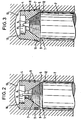
- the anchor bolt 1 partially shown in FIG. 1 contains a cylindrical shaft 2 and an expansion sleeve 4 placed on the rear end 3 of this shaft - in the illustration according to FIG. 1 it is the upper end.
- the cylindrical shaft 2 can, as shown, have a smooth outer surface, it can also be provided with a thread, in particular if use as a composite anchor is desired, in which a composite is produced by means of a mortar compound introduced into the borehole by means of a mortar cartridge.
- the front end of the shaft is adapted to the purpose of the anchor bolt and can have a profile section which is suitable for insertion into a drill or hammer drill.
- the rear end 3 of the shaft 2 tapers, in the case shown in the manner of a truncated cone which is provided with an external thread 5.
- the expansion sleeve 4 has an axial bore 6 which widens conically towards the front and is provided with an internal thread 7 which is adapted to the external thread (see FIG. 2).
- the expansion sleeve 4 In order to allow the expansion sleeve 4 to expand, it has longitudinal slots 8 which are evenly distributed around the circumference and which extend from the front end face 9 of the expansion sleeve so far to the rear that the desired expansion effect can be achieved.
- the rear end face of the expansion sleeve 4 is designated 10, it also forms the rear end of the anchor bolt.
- Cutting elements 11 protrude from the lateral surface of the expansion sleeve 4, by means of which the undercut is produced. These cutting elements 11 must be provided in particular in the area of the lateral surface of the expansion sleeve adjoining the front face 9, since in this area a shoulder-shaped undercut is to be produced as a contact surface for the front face 9 of the expansion sleeve.
- the cutting elements 11 are formed by cutting inserts. However, corresponding cutting edges could also be formed from the material of the expansion sleeve itself, for example by protruding cutting edges which are formed during the production of the slots 8.
- the outer diameter of the expansion sleeve 4 corresponds approximately to the outer diameter of the shaft 2 and the diameter of the envelope of the above cutting elements 11 corresponds approximately to the inner diameter of the predrilled hole into which the anchor bolt is to be inserted. It can also be slightly larger.
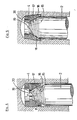
- Fig. 2 represents the above in a longitudinal sectional view Ren part of the anchor bolt 1 of FIG. 1 inserted into a borehole 12.
- This illustration also shows that the axial bore 6 is widened conically towards the front (downward in the drawing) and has the internal thread 7.
- This hole is also enlarged at the rear in order to reduce the rigidity somewhat in this area in which the longitudinal slots 8 end.
- the anchor bolt is inserted into the pilot hole 12 until, as shown, the rear end face 10 of the expansion sleeve 4 abuts the bottom 13 of the borehole.
- the shaft is now rotated by means of a drill so that the external thread 5 penetrates into the internal thread 7, the expansion sleeve is taken along and the state shown in FIG.
- projections can be attached, by which the holding of the expansion sleeve on the drill base is promoted when the shaft penetrates.
- the expansion sleeve is temporarily entrained in the direction of rotation due to a frictional connection between the external thread of the shaft and the internal thread of the expansion sleeve.
- the force that can be transmitted through the frictional connection must at times be greater than the holding force of the expansion sleeve in the borehole.
- the rotation of the expansion sleeve required for the undercutting process when driving in the shaft depends not only on the size and frequency of the impact stress and the distribution of the cutting elements, but also on the angle of inclination of the tapered section and the angle of the tooth flanks of the thread, which occurs during impact stress be pressed together.
- the angle of inclination of the tapered section based on the central axis, is preferably between 10 and 30 ° .
- the angle of the tooth flanks, with respect to a perpendicular to the central axis allows the normal component acting on the friction surface during an axial impact movement of the shaft to be controlled. The smaller this angle, the larger the normal component and thus the frictional force.
- a further control of the entrainment of the expansion sleeve when turning the shaft can also be achieved in that the slopes of the internal thread of the expansion sleeve and the external thread on the tapered section of the shaft are designed somewhat differently from one another. If this measure is provided in the rear area, then it is ensured that at the end of the expansion process of the sleeve, the sleeve rotates with it, so that the expansion sleeve can be seated in the borehole without expansion pressure.
- the threaded connection also forms the positive connection acting in the pulling-out direction of the shaft.
- the front tooth flanks of the external thread applied to the shaft that is to say the tooth flanks which are located on the side facing away from the rear shaft end, run approximately perpendicular to the shaft axis. If the angle of inclination of these tooth flanks with respect to the shaft axis is increased to values above 45 ° , a sufficient form fit in the direction of extension of the shaft is no longer guaranteed.
- the cross-section of the anchor bolt effective for the tensile load is increased compared to the known anchorages of the type mentioned in the introduction, since a conical thread is used to anchor the bolt in the expansion sleeve and part of the expansion sleeve is forced into the undercut region of the borehole.
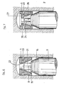
- FIGS. 4 and 5 differs from that of FIGS. 2 and 3 essentially in that the connection between the shaft and the expansion sleeve is not a saw profile formed by a thread, but a saw profile formed by circumferential grooves.
- the shaft 2 has in the tapering section at the rear end a saw profile 15 formed by circumferential grooves and the expansion sleeve 4 has a complementary saw profile 16.
- the rear tooth flanks 17 of the saw profile 15, that is to say the tooth flanks on the side facing the rear shaft end, run obliquely and the front tooth flanks 18 approximately perpendicular to the shaft axis.
- the angle of inclination of the rear tooth flanks as already described in the exemplary embodiment of FIGS.
- the rear tooth flanks 17 of the saw profile 15 are pressed against the front tooth flanks 19 of the saw profile 16 of the expansion sleeve 4 and these are rotated at times by overcoming the retention force of the expansion sleeve in the borehole .
- the conical end of the shaft 2 penetrates into the expansion sleeve, and the rear tooth flanks 17 of the shaft 2 move due to the impact stress in the axial direction of the shaft relative to the front tooth flanks 19 of the expansion sleeve 4 until the saw profiles 15 and 16 around a tooth have shifted against each other and interlock again while springing back the expansion sleeve.
- the measures for the undercut process can be carried out here irrespective of the measures for anchoring the shaft 2 in the expansion sleeve 4, and for example a rotational coupling between the shaft and the expansion sleeve is possible over the entire driving-in process of the shaft.
- a positive engagement acting in the direction of rotation could be provided as in the known methods described in the introduction, which allows the expansion sleeve to be taken along without slippage during the entire setting process.
- the shaft 2 carries, after the tapered section with a saw profile 15, a threaded shoulder 21 which engages in a threaded section 22 of the expansion sleeve 4.
- the expansion sleeve 4 approximately in the area in which the longitudinal slots 8 end, a circumferential groove 23 through which the rigidity of the expansion sleeve is reduced at this point and at the same time it is prevented that the expansion of the expansion sleeve in the lower region of the threaded portion 22 is impermissibly strong is deformed.
- This threaded section is provided in connection with the threaded shoulder 21 to provide the necessary axial advance of the shaft 2 during the driving-in movement in addition to or instead of a striking movement by the setting tool.
- the saw profiles 15 and 16 are designed in the same way as in the embodiment according to FIGS. 4 and 5 and also perform the same function. Otherwise, the threaded attachment 21 in connection with a threaded portion 22 can also be used in an embodiment according to FIGS. 2 and 3. In this case, however, the thread pitches of the thread provided on the tapered section of the shaft 2 and of the thread provided on the thread attachment must be adapted to one another.
- the shaft 2 has a projection 24 which engages in a groove 25 of the expansion sleeve 4 to form a positive connection acting in the direction of rotation.
- the projection 24 is attached to a cylindrical extension 26 of the shaft 2 and the arrangement and length of the groove 25 are selected such that the positive engagement acting in the direction of rotation is released in the rear region of the driving-in section.
- the expansion sleeve has a cutout 27 on the rear side, into which the projection 24 emerges at the end of the driving-in section and can rotate freely.
- the rotational connection does not have to be canceled if a saw profile formed by circumferential grooves is used as the connection between the shaft and the expansion sleeve.
- the anchor bolt As in the first exemplary embodiment, there is a threaded connection between the shaft 2 and the expansion sleeve 4.
- two driver pins 28 are provided to produce a temporary rotation, which are dimensioned so that they shear off by a rotating resistance increasing when driving.
- driver pins of this type it is possible to control the temporary rotation of the expansion sleeve 4 during the undercut process. The undercut process can then also be ensured if the frictional engagement between the thread flanks cannot be dimensioned sufficiently large.
- the expansion sleeve 4 is formed with at least one run-up edge against which the driver pins abut when the shaft is screwed into the expansion sleeve.
- the front annular end face or an edge of a longitudinal slot 8 can serve as the leading edge.
- a section 29 of the front end face of the expansion sleeve 4 is designed to increase in the circumferential direction, the pitch angle being selected to be somewhat smaller than that of the internal thread of the expansion sleeve, and this section is provided as a leading edge for the driving pins 28.
- the angle of inclination of the tapered portion of the shaft is reduced compared to the first embodiment, which also reduces the forces which can be transmitted by the frictional engagement.
- the shaft 2 is screwed into the sleeve 4, then this is initially spread while the expansion sleeve is held in the borehole until the driving pin 28 shown in FIG. 8 meets the leading edge 29. This takes the expansion sleeve with it, wherein the leading edge exerts a shear force on the driver pin.
- This shear force fluctuates with a striking load within wide limits if, as shown in the embodiment according to FIG. 8, a profile 30 is provided on the rear end face of the expansion sleeve 4, which suddenly increases the holding force of the expansion sleeve in the borehole in the event of an impact load.
- the upper driving pin 28 is finally sheared off and, with the expansion sleeve 4 held in the borehole, the shaft 2 is further screwed in until the next driving pin 28 abuts an edge of the expansion sleeve 4 and, with suitable dimensioning, causes the expansion sleeve to be carried briefly while increasing the undercut.
- the expansion sleeve 4 is formed in two parts, one part is rotatably inserted into the borehole and is used to produce the positive connection required in the pull-out direction of the shaft, while the other part for producing the undercut during the driving-in movement of the shaft is also rotated.
- the expansion sleeve 4 consists of the front part 4a and the rear part 4b, which are rotatable relative to one another and are positively connected in the pull-out direction of the shaft.
- the front part 4a of the expansion sleeve is provided with a conical bore 31, the rear part contains a threaded section 22.
- the tapered section to be driven into the conical bore at the rear end of the shaft 2 is conical, the cone angle being approximately the angle of the conical Bore in the spread state of the front part 4a of the expansion sleeve 4 corresponds.
- the shaft 2 carries at the rear end a threaded projection 21 which engages in the threaded section 22 of the expansion sleeve 4 when the anchor bolt is set.
- Retaining pins 33 are provided on the rear end face of the rear part 4b of the expansion sleeve 4, which are intended to ensure that the rear part does not rotate when the shaft 2 is driven into the expansion sleeve.
- the shaft has projections which protrude from the conical surface and which engage in the longitudinal slots 8 of the front part 4a of the expansion sleeve.
- the shaft is driven into the expansion sleeve 4 by means of a rotating movement.
- the rear part 4b is held by the retaining pins 33 in the borehole, while the front part 4a is rotated as a result of the engagement between the projections 34 and the slots 8.
- the front part 4a of the expansion sleeve is spread and the undercut is produced in the borehole by the axial movement which the shaft 2 carries out.
- the threaded shoulder 21 of the shaft 2 is screwed into the threaded section 22 of the expansion sleeve 4.
- This threaded connection then represents the positive connection acting in the pulling-out direction of the shaft.
- the front and the rear part of the expansion sleeve 4 can be two separate ring parts which, as shown in FIG. 9, are held on the shaft 2 in that one or two threads of the threaded projection 21 engage in the threaded section 22.
- connection between the shaft and the front part 4a of the expansion sleeve 4 is designed as a cone connection with a smooth outer surface.
- a threaded connection as in the first exemplary embodiment or a saw profile formed by circumferential grooves as in the second exemplary embodiment can also be selected here.
- FIG. 10 shows a longitudinal section of the expansion sleeve 4
- FIG. 11 shows the section XI-XI from FIG. 10
- FIG. 12 shows a representation of the expansion sleeve corresponding to FIG. 10 in the expanded state within the borehole
- FIG. 13 shows the rear part of the shaft 2nd
- Four projections 34 are provided on the shaft, each of which engages in an axially aligned groove, that is to say in the present case in a longitudinal slot 8 of the expansion sleeve 4.
- the expansion sleeve can be set in rotation when driving in via the rotary connection formed in this way.
- a circumferential groove 35 which is connected to the relevant axial groove 8, is assigned to each axially aligned groove 8 at the end of the driving-in section.
- the protrusions 34 are inserted into the circumferential grooves 35 by the stripping movement, thereby producing the positive connection between the shaft and the expansion sleeve that acts in the pull-out direction of the shaft.
- the shaft has been shown as a full shaft in the exemplary embodiments, it can also be hollow. Likewise, the slots of the expansion sleeve do not need to run parallel to the central axis of the expansion sleeve, but can be arranged obliquely.
- the bore of the expansion sleeve does not have to have the same taper angle as the tapered section of the shaft. It can also be cylindrical in the area receiving the tapering section.
- the complementary saw profile present in the expansion sleeve does not have to be exactly adapted to the tapering section of the shaft. It is essential that the functions described in this application be fulfilled. In view of this, it is more expedient if the profiles are adapted to one another in the spread state than in the non-spread state.
- the shaft 2 is hollow, ie in the form of a sleeve and this has an internal thread.
- a connection tion in the form of a saw profile, preferably a threaded connection, similar to the example shown in FIG. 1.
- the longitudinal slots 8 of the expansion sleeve 4 end shortly in front of the front end face 9, in order initially to achieve a higher frictional engagement when screwing the shaft 2 into the expansion sleeve 4.
- the thin connecting webs at the front end of the longitudinal slots 8 break and the expansion sleeve is expanded as described.
- Protruding cutting edges 11 arranged helically are provided here as cutting elements.
- the arrangement of the helical lines can be opposite in the case of a sleeve, as shown in FIG. 14. Otherwise, retaining strips 14 are provided on the rear end face, which correspond to the retaining pins 33 of the embodiment according to FIG. 9.
Landscapes
- Engineering & Computer Science (AREA)
- General Engineering & Computer Science (AREA)
- Mechanical Engineering (AREA)
- Dowels (AREA)
- Joining Of Building Structures In Genera (AREA)
Description
Die Erfindung betrifft ein Verfahren zum Einsetzen eines Ankerbolzens in ein Bohrloch eines Befestigungsgrundes gemäß dem Gattungsbegriff des Patentanspruches 1. Ferner betrifft die Erfindung einen Ankerbolzen für ein derartiges Verfahren gemäß dem Gattungsbegriff der Patentansprüche 15, 25 bzw. 32.The invention relates to a method for inserting an anchor bolt into a borehole of a fastening base according to the preamble of
Ein Verfahren der genannten Art ist beispielsweise durch DE-U 8 125 545 und DE-A 3 509 624, Offenlegungstag 18.9.86, bekannt geworden. Bei dem bekannten Verfahren wird eine Spreizhülse mit ihrem hinteren Ende voran in ein Bohrloch des Befestigungsgrundes eingeführt. Die Spreizhülse weist von einer vorderen ringförmigen Stimfläche ausgehende Schlitze sowie in dem an diese Stimfläche angrenzenden Bereich der Mantelfläche aus dieser vorstehende Schneidelemente auf. Im hinteren Abschnitt der Spreizhülse ist ein Innengewinde vorgesehen.A method of the type mentioned has become known, for example, from DE-U 8 125 545 and DE-A 3 509 624, publication date September 18, 1986. In the known method, an expansion sleeve is inserted with its rear end first into a borehole in the fastening base. The expansion sleeve has slots extending from a front annular end face and in the region of the outer surface adjacent to this end face, protruding cutting elements. An internal thread is provided in the rear section of the expansion sleeve.
Durch Eintreiben eines sich verjüngenden Abschnittes am hinteren Ende eines Schaftes eines Setzwerkzeuges in die Spreizhülse mittels einer Axial- und Drehbewegung wird die Spreizhülse gespreizt und in Drehung versetzt und hierdurch im Bohrloch eine Hinterschneidung mit einem Absatz vor der vorderen Stirnfläche der Spreizhülse erzeugt. Um zu erreichen, daß sich die Spreizhülse beim Drehen des Setzwerkzeuges mitdreht, ist der sich verjüngende Abschnitt des Schaftes mit einer Längsprofilierung versehen bzw. es ist ein in Drehrichtung wirkender Formschluß zwischen Schaft und Spreizhülse vorgesehen. Zu diesem Zweck trägt der Schaft Vorsprünge, die in Längsnuten der Spreizhülse eingreifen.By driving a tapered section at the rear end of a shank of a setting tool into the expansion sleeve by means of an axial and rotary movement, the expansion sleeve is spread and rotated, thereby producing an undercut in the borehole with a shoulder in front of the front end face of the expansion sleeve. In order to ensure that the expansion sleeve also rotates when the setting tool is rotated, the tapering section of the shaft is provided with a longitudinal profile or a positive connection acting in the direction of rotation is provided between the shaft and the expansion sleeve. For this purpose, the shaft carries projections which engage in the longitudinal grooves of the expansion sleeve.
Nach Erzeugen der Hinterschneidung im Bohrloch mittels einer drehenden und schlagenden Bewegung des Setzwerkzeuges wird dieses wieder aus dem Bohrloch entfernt und in den hinteren Gewindeabschnitt der nunmehr im Bohrloch verankerten Spreizhülse ein Gewindebolzen eingeschraubt, der mit der Spreizhülse den im 8ohnoch verankerten Ankerbolzen bildet. Die Gewindeverbindung zwischen dem Gewindebolzen und der Spreizhülse stellt hierbei einen in Ausziehrichtung des Gewindebolzens wirkenden Formschluß dar.After creating the undercut in the borehole by means of a rotating and striking movement of the setting tool, the setting tool is removed from the borehole again and a threaded bolt is screwed into the rear threaded section of the expansion sleeve now anchored in the borehole, which forms the anchor bolt anchored in the 8o hole with the expansion sleeve. The threaded connection between the threaded bolt and the expansion sleeve represents a positive connection acting in the pulling-out direction of the threaded bolt.
Verankerungen dieser Art können spreizdruckfrei ausgebildet sein, durch die Hinterschneidung im Bohrloch entsteht eine annähernd quer zur Längsachse der Bohrung gerichtete Stützschulter, welche die Zugbelastung des Ankerbolzens ohne Keilwirkung für den Untergrund aufnimmt, so daß derartige Verankerungen insbesondere für den Einsatz in rißgefährdeten Zugzonen des Befestigungsgrundes geeignet sind.Anchors of this type can be designed without expansion pressure, the undercut in the borehole creates a support shoulder which is approximately transverse to the longitudinal axis of the bore and which absorbs the tensile load of the anchor bolt without wedge action for the subsoil, so that such anchors are particularly suitable for use in tensile zones of the fastening base which are at risk of cracking are.
Zur Herstellung der Hinterschneidung im Bohrloch und zum Verankern des Bolzens in der Spreizhülse sind allerdings zwei Verfahrensschritte erforderlich, nämlich das Eintreiben des Schaftes eines Setzwerkzeuges mittels einer schlagenden und drehenden Bewegung in die Spreizhülse und nach Entfernen des Setzwerkzeuges das Einschrauben des Bolzens in die verankerte Spreizhülse. Außerdem ist der für die Zugbelastung wirksame Querschnitt des Bolzens durch den Durchmesser des Innengewindes der Spreizhülse bestimmt, der im Hinblick auf eine ausreichende Materialstärke der Spreizhülse stets wesentlich kleiner als der Durchmesser des Bohrloches im Befestigungsgrund ist.However, two process steps are required to produce the undercut in the borehole and to anchor the bolt in the expansion sleeve, namely driving the shaft of a setting tool into the expansion sleeve by means of a striking and rotating movement and, after removing the setting tool, screwing the bolt into the anchored expansion sleeve. In addition, the cross-section of the bolt effective for the tensile load is determined by the diameter of the internal thread of the expansion sleeve, which is always substantially smaller than the diameter of the borehole in the fastening base in view of a sufficient material thickness of the expansion sleeve.
Durch DE-A 3 139 174 ist ein Ankerbolzen bekannt geworden, der einen zylindrischen Schaft und einen im Durchmesser vergrößerten spreizbaren Kopf aufweist, an dessen hinterem Ende wenigsten zwei sich radial gegenüberliegende, als Hartmetallstifte ausgebildete Schneidelemente angeordnet sind, die radial über den Umfang des Kopfes hin ausragen. Der Kopf weist ferner an der hinteren Stirnseite einen axial verlaufenden Schlitz auf, in den ein axial verschiebbarer Spreizkeil mit seinem verjüngten Ende hineinragt. Zum Einsetzen dieses Ankerbolzens in einen Befestigungsgrund wird hier zunächst eine zylindrische Bohrung eingebracht, dann eine Mörtelpatrone in die Bohrung eingeschoben und schließlich der Ankerbolzen zusammen mit dem im axial verlaufenden Schlitz eingeklemmten Spreizkeil in die Bohrung unter drehend-schlagender Bewegung und stetigem axialen Druck eingeführt, wobei die Mörtelpatrone zerstört und ihr Inhalt vermischt wird. Sobald die Spitze des Spreizkeils den Bohrlochgrund erreicht hat, wird der Kopf über den im Bohrloch aufstehenden Spreizkeil geschoben. Hierbei werden die Schneidelemente entsprechend der Spreizung des Kopfes durch den Spreizkeil gegen die Bohrlochwandung gedrückt und ein sich kegelförmig erweiternder Hinterschnitt erzeugt. Der Übergang vom Schaft zum Kopf des Ankerbolzens kann in Form einer stufenförmigen Erweiterung ausgebildet sein, durch die eine Ringschulter gebildet wird, die sich gegen die durch die Mörtelpatrone eingebrachte Mörtelmasse abstützt und hierdurch einen geringen Anfangsschlupf bewirkt.An anchor bolt is known from DE-A 3 139 174, which has a cylindrical shaft and an expandable head with an enlarged diameter, at the rear end of which at least two radially opposite cutting elements designed as hard metal pins are arranged, which extend radially over the circumference of the head stick out. The head also has an axially extending slot on the rear face into which an axially displaceable expanding wedge projects with its tapered end. To insert this anchor bolt into a fastening base, a cylindrical bore is first made here, then a mortar cartridge is inserted into the bore and finally the anchor bolt together with the expanding wedge clamped in the axially extending slot is inserted into the bore under rotationally striking movement and constant axial pressure, whereby the mortar cartridge is destroyed and its contents are mixed. As soon as the tip of the expanding wedge has reached the bottom of the borehole, the head is pushed over the expanding wedge standing up in the borehole. Here, the cutting elements are pressed against the borehole wall by the expansion wedge in accordance with the expansion of the head, and an undercut which widens in a conical shape is produced. The transition from the shaft to the head of the anchor bolt can be designed in the form of a step-like extension, through which an annular shoulder is formed, which is supported against the mortar mass introduced by the mortar cartridge and thereby causes a small initial slippage.
Im allgemeinen vermag sich der Anker bei einer Rißbildung im Bereich der Bohrung nicht mehr durch seine Schulter an der eingebrachten Mörtelmasse abzustützen, da diese dann den Beanspruchungen nicht mehr standhält, sondern er wird so weit herausgezogen, bis der gespreizte Kopf mit der abgeschrägten Bohrlochwandung in Berührung kommt. Hierdurch wird ein in vielen Fällen unzulässiger Schlupf bewirkt.In general, the anchor is no longer able to support the inserted mortar mass through its shoulder in the event of a crack formation in the area of the bore, since this then no longer withstands the stresses, but is pulled out until the spread head comes into contact with the chamfered borehole wall is coming. This causes an inadmissible slip in many cases.
Durch die US-A 3 848 506 ist ein Ankerbolzen mit einem zylindrischen Schaft bekannt geworden, dessen hinteres Ende einen sich verjüngenden Abschnitt enthält, auf den eine Spreizhülse aufgesetzt ist, die von einer vorderen ringförmigen Stimfläche ausgehende Schlitze aufweist und aus ihrer Mantelfläche vorstehende Elemente enthält. Der sich verjüngende Abschnitt am Ende des Schaftes ist mit einem Außengewinde versehen und die Spreizhülse weist ein daran angepaßtes Innengewinde auf. Die Spreizhülse kann aus einzelnen, durch einen Federring zusammengehaltenen Segmenten bestehen.An anchor bolt with a cylindrical shank is known from US Pat. No. 3,848,506, the rear end of which contains a tapering section onto which an expansion sleeve is fitted, which has slots extending from a front annular end face and contains elements protruding from its outer surface . The tapered section at the end of the shaft is provided with an external thread and the expansion sleeve has an internal thread adapted to it. The expansion sleeve can consist of individual segments held together by a spring ring.
Der Ankerbolzen wird in ein Bohrloch eines Befestigungsgrundes eingeführt und dann durch Drehen des Schaftes der mit dem Außengewinde versehene, sich verjüngende Abschnitt in die Spreizhülse eingeschraubt und hierbei ein Spreizen und Anpressen der Hülse an die Innenwand des Bohrloches erreicht. Durch die aus der Mantelfläche vorstehenden Elemente wird in Verbindung mit einem kleinen Konuswinkel des Innengewindes sichergestellt, daß sich diese beim Einschrauben des Schaftes nicht mitdrehen kann. Die Verankerung im Bohrloch des Befestigungsgrundes erfolgt hier über die Spreizkraft der Hülse. Der für die Zugbelastung wirksame Querschnitt ist hier ähnlich reduziert wie bei der eingangs beschriebenen Verankerung.The anchor bolt is inserted into a borehole of a fastening base and then, by rotating the shaft, the tapered section provided with the external thread is screwed into the expansion sleeve, thereby spreading and Press the sleeve against the inner wall of the borehole. The elements protruding from the outer surface, in conjunction with a small cone angle of the internal thread, ensure that it cannot rotate when the shaft is screwed in. The anchorage in the borehole of the fastening base takes place here via the expansion force of the sleeve. The cross-section effective for the tensile load is reduced here in a similar way to the anchoring described at the beginning.
Aufgabe der Erfindung ist es , bei einem Verfahren der einleitend genannten Art durch die Eintreibbewegung des Schaftes sowohl die Hinterschneidung im Bohrloch herzustellen als auch den Bolzen in der Spreizhülse zu verankern, das heißt,das Setzen des Ankerbolzens mit einem einzigen Verfahrensschritt zu ermöglichen.The object of the invention is to produce both the undercut in the borehole and to anchor the bolt in the expansion sleeve in a method of the type mentioned in the introduction by anchoring the shaft, that is to say to enable the setting of the anchor bolt with a single method step.
Ferner ist es Aufgabe der Erfindung, Ankerbolzen für ein derartiges Verfahren verfügbar zu machen. Schließlich soll eine Vergrößerung des für die Zugbelastung wirksamen Querschnittes des Ankerbolzens ermöglicht werden.It is also an object of the invention to make anchor bolts available for such a method. Finally, an increase in the cross section of the anchor bolt effective for the tensile load should be made possible.
Das erfindungsgemäße Verfahren ist durch die Merkmale des Anspruches 1 gekennzeichnet. Vorteilhafte Ausgestaltungen des Verfahrens sind den Ansprüchen 2 bis 14 zu entnehmen.The method according to the invention is characterized by the features of
Erfindungsgemäße Ankerbolzen sind durch die Merkmale der Ansprüche 15, 25 und 32 gekennzeichnet. Vorteilhafte Ausgestaltungen dieser Ankerbolzen sind in den restlichen Ansprüchen angegeben.Anchor bolts according to the invention are characterized by the features of
Bei dem Verfahren und den Ankerbolzen gemäß dieser Erfindung ist die Verbindung zwischen Schaft und Spreizhülse so ausgebildet, daß durch einen in Drehrichtung wirkenden Formschluß und/oder durch einen Reibungsschluß zwischen Schaft und Spreizhülse diese beim Eintreiben des Schaftes in die Spreizhülse wenigstens zeitweise mitgedreht und am Ende des Spreizvorganges zwischen Spreizhülse und Schaft ein in Ausziehrichtung des Schaftes wirkender Formschluß hergestellt wird. Damit ist es möglich, den Schaft zugleich als in der Spreizhülse verankerten Bolzen zu benutzen, so daß der Ankerbolzen mit einem einzigen Verfahrensschritt gesetzt werden kann.In the method and the anchor bolt according to this invention, the connection between the shaft and the expansion sleeve is designed such that by a positive connection acting in the direction of rotation and / or by a frictional connection between the shaft and the expansion sleeve, these are at least temporarily rotated when the shaft is driven into the expansion sleeve and at the end of the expansion process between the expansion sleeve and the shaft, a form-fit acting in the pulling-out direction of the shaft is produced. This makes it possible to use the shaft at the same time as the bolt anchored in the expansion sleeve, so that the anchor bolt can be set in a single process step.
Hierbei sind zwei gegensätzliche Forderungen zu erfüllen. Zur Herstellung der Hinterschneidung ist es erforderlich, die Spreizhülse mitzudrehen und beim Einschrauben des Bolzens in die Spreizhülse zur Herstellung des in Ausziehrichtung wirkenden Formschlusses muß ein Mitdrehen der Spreizhülse verhindert werden. Diese gegensätzlichen Forderungen lassen sich beispielsweise dadurch erfüllen, daß die Spreizhülse zweiteilig ausgebildet wird, wobei der eine Teil drehfest in das Bohrloch eingesetzt wird und der andere Teil zur Herstellung der Hinterschneidung mitgedreht wird. Die gegensätzlichen Forderungen lassen sich auch bei einer einstückigen Spreizhülse realisieren, wenn hier für den in Ausziehrichtung des Bolzens wirkenden Formschluß ein absatzförmiger Eingriff zwischen Schaft und Spreizhülse gewählt wird, der alleine durch die Axialbewegung des Schaftes unter kurzzeitigem Spreizen und Zurückfedern der Spreizhülse herstellbar ist. Besonders geeignet hierfür ist ein durch Umfangsrillen gebildetes Sägen profil zwischen Schaft und Spreizhülse. Im Gegensatz zu einer Gewindeverbindung ist hier zur Herstellung des in Ausziehrichtung wirkenden Formschlusses zwischen Spreizhülse und Schaft keine relative Drehbewegung erforderlich, sondern nur eine Axialbewegung, so daß der den Bolzen bildende Schaft in der Hülse auch verankert werden kann, wenn diese auf der gesamten Eintreibstrecke drehfest mit dem Schaft verbunden ist.Two conflicting requirements have to be met. To produce the undercut, it is necessary to also rotate the expansion sleeve and when the bolt is screwed into the expansion sleeve to produce the positive connection acting in the direction of extraction, the expansion sleeve must also be prevented from rotating. These conflicting requirements can be met, for example, in that the expansion sleeve is formed in two parts, one part being inserted into the borehole in a rotationally fixed manner and the other part being rotated to produce the undercut. The opposite requirements can also be realized in the case of a one-piece expansion sleeve if a shoulder-shaped engagement between the shaft and expansion sleeve is selected here for the positive engagement acting in the pull-out direction of the bolt, which engagement can be produced solely by the axial movement of the shaft with brief expansion and spring-back of the expansion sleeve. Particularly suitable for this is a sawing profile formed by circumferential grooves between the shaft and the expansion sleeve. In contrast to a threaded connection, no relative rotary movement is required to produce the positive connection between the expansion sleeve and shaft acting in the pull-out direction, but only an axial movement, so that the shaft forming the bolt can also be anchored in the sleeve if it is rotatably fixed over the entire driving-in distance is connected to the shaft.
Es ist auch möglich, die beiden gegensätzlichen Forderungen dadurch in Einklang zu bringen, daß zunächst eine drehschlüssige Verbindung und am Ende eine drehfreie Verbindung vorgesehen wird, beispielsweise durch einen aus dem Schaft vorstehenden Vorsprung, der zunächst in einer axial ausgerichteten Nut der Spreizhülse geführt wird, die am Ende der Eintreibstrecke in eine Umfangsnut übergeht. Schließlich ist es auch möglich, einen eine Relativdrehung verlangenden axialen Formschluß, wie eine Gewindeverbindung, neben der Herstellung der Hinterschneidung zu realisieren, wenn während des Drehens des Schaftes bei der Eintreibbewegung die Spreizhülse zeitweise mitgenommen wird und zeitweise im Bohrloch festgehalten wird, oder wenn während des Eintreibens des Schaftes in die Spreizhülse zwischen beiden Teilen ein Schlupf ermöglicht wird. Ein solcher Verfahrensablauf läßt sich auf einfache Weise über eine Reibungsverbindung zwischen Schaft und Spreizhülse realisieren, insbesondere bei Anwendung einer mit einer Schlagbewegung gekoppelten Drehbewegung beim Eintreiben des Schaftes.It is also possible to reconcile the two opposing requirements by first providing a rotational connection and at the end a non-rotating connection, for example by means of a projection protruding from the shaft, which is first guided in an axially aligned groove of the expansion sleeve, which merges into a circumferential groove at the end of the driving-in section. Finally, it is also possible to realize an axial positive connection, such as a threaded connection, which requires a relative rotation, in addition to producing the undercut, if the expansion sleeve is temporarily carried along during the driving-in movement during the driving-in movement and is temporarily held in the borehole, or if during the Driving the shaft into the expansion sleeve between two parts, a slip is made possible. Such a process sequence can be implemented in a simple manner via a friction connection between the shaft and the expansion sleeve, in particular when using a rotary movement coupled with a striking movement when driving in the shaft.
Es können zur Realisierung nur eines zeitweisen Mitdrehens im Verbindungsbereich zwischen Schaft und Spreizhülse auch Mitnehmerstifte vorgesehen werden, die durch einen sich beim Eintreiben vergrößernden Drehwiderstand abscheren und dann eine Relativdrehung zwischen Schaft und Hülse zulassen.For realizing only temporary rotation in the connection area between the shaft and the expansion sleeve, driving pins can also be provided, which shear off due to an increasing rotational resistance when driving in and then allow a relative rotation between the shaft and the sleeve.
Die Axialbewegung beim Eintreiben des Schaftes in die Spreizhülse kann über das Setzwerkzeug aufgebracht werden. Sie kann auch von der Drehbewegung des Setzwerkzeuges abgeleitet werden, indem ein am hinteren Ende des Schaftes vorhandener Gewindeansatz in einen Gewindeabschnitt der Spreizhülse eingedreht wird.The axial movement when driving the shaft into the expansion sleeve can be applied using the setting tool. It can also be derived from the rotary movement of the setting tool by screwing a threaded attachment present at the rear end of the shaft into a threaded section of the expansion sleeve.
ist bei dem erfindungsgemäßen Ankerbolzen die Spreizhülse mit Längsschlitzen oder Längsnuten versehen, die nahezu bis zum Kopfende reichen, dann erfolgt beim Eindringen des Schaftes eine stärkere Spreizung im vorderen Bereich der Spreizhülse als im hinteren Bereich. Die Spreizhülse kann aber auch aus mehreren Segmenten gebildet sein, die dann entstehen, wenn die Hülse an mehreren Stellen des Umfangs axial geschnitten wird. In diesem Fall müssen die Segmente durch wenigstens einen Federring zusammengehalten werden. Vorzugsweise sind zwei Federringe am hinteren und am vorderen Ende der so gebildeten Spreizhülse vorhanden. Beim Eindringen des hinteren konischen Endes des Schaftes in die so ausgebildete Spreizhülse werden die Segmente nahezu auf ihrer gesamten Länge parallel nach außen verschoben und bilden eine im wesentlichen zylindrische Hinterschneidung mit einem Absatz auf dem sich die vordere Stirnfläche der Spreizhülse abstützt.If the expansion sleeve in the anchor bolt according to the invention is provided with longitudinal slots or longitudinal grooves which extend almost to the head end, then when the shaft penetrates, there is a greater spread in the front area of the expansion sleeve than in the rear area. The expansion sleeve can, however, also be formed from a plurality of segments which arise when the sleeve is axially cut at a plurality of points on the circumference. In this case, the segments must be held together by at least one spring ring. There are preferably two spring washers at the rear and at the front end of the expansion sleeve formed in this way. When the rear conical end of the shaft penetrates into the expansion sleeve formed in this way, the segments are displaced outward almost over their entire length and form an essentially cylindrical one Undercut with a shoulder on which the front face of the expansion sleeve is supported.
Die Verbindung zwischen dem hinteren Schaften-- de und der Spreizhülse ist so ausgebildet, daß die Spreizhülse gespreizt und gedreht werden kann. Falls ein kraftschlüssiger Sitz in der Hinterschneidung gewünscht ist, soll nach dem Erzeugen der Hinterschneidung die Spreizhülse ohne Drehen um ein vorgegebenes Maß weitergespreizt werden können. Außerdem muß im eingesetzten Zustand des Ankerbolzens gewährleistet sein, daß sich auch bei einer Rißbildung im Bereich des Bohrloches das Schaftende nicht aus der Spreizhülse lösen kann.The connection between the rear shaft end and the expansion sleeve is designed so that the expansion sleeve can be expanded and rotated. If a non-positive fit is desired in the undercut, the expansion sleeve should be able to be expanded further by a predetermined amount after the undercut has been created. In addition, in the inserted state of the anchor bolt, it must be ensured that even if there is a crack in the area of the borehole, the shaft end cannot come loose from the expansion sleeve.
Die genannten Forderungen lassen sich vorteilhaft und mit enem geringen Aufwand dadurch erfüllen, daß das sich verjüngende Ende des Schaftes wenigstens auf einem Teil seiner Länge mit einem Außengewinde versehen ist und die Spreizhülse ein daran angepaßtes Innengewinde aufweist. Bei geeigneter Wahl des Neigungswinkels der Verjüngung, der sich auch etwas ändern kann, sowie der Steigung des Gewindes läßt sich erreichen, daß beim Eindrehen des Schaftendes in die Spreizhülse diese mitgenommen wird und sich gleichzeitig spreizt und so der Hinterschnitt erzeugt wird. Durch einen zusätzlichen axialen Druck am Ende des Hinterschneidvorgangs läßt sich die Reibung zwischen dem Bohrgrund und der Spreizhülse erhöhen, so daß diese beim Weiterdrehen des Schaftes nicht mehr mitgenommen wird, sondern nur noch um ein vorgegebenes Maß gespreizt wird. Das Festhalten kann durch auf die hintere Stirnseite der Spreizhülse aufgebrachte Vorsprünge begünstigt werden.The requirements mentioned can be met advantageously and with little effort in that the tapered end of the shaft is provided with an external thread over at least part of its length and the expansion sleeve has an internal thread adapted to it. With a suitable choice of the angle of inclination of the taper, which can also change somewhat, and the pitch of the thread, it can be achieved that when the shaft end is screwed into the expansion sleeve, the latter is carried along and at the same time spreads and the undercut is thus produced. An additional axial pressure at the end of the undercutting process increases the friction between the drill base and the expansion sleeve, so that it is no longer carried along when the shaft is turned further, but is only expanded by a predetermined amount. Holding on can be promoted by projections provided on the rear end face of the expansion sleeve.
Es ist auch möglich, bei geeigneter Materialauswahl und Bemessung der Schneidelemente sich deren Abrieb beim Hinterschneidvorgang zunutze zu machen und das Festhalten der Spreizhülse am Ende des Hinterschneidvorgangs durch vergrößerte Reibung aufgrund eines vergrößerten Flächenkontaktes zwischen der Mantelfläche der Spreizhülse und der Bohrlochwandung zu bewirken.It is also possible, with a suitable choice of material and dimensioning of the cutting elements, to take advantage of their abrasion during the undercutting process and to cause the expansion sleeve to be held at the end of the undercutting process by increased friction due to an increased surface contact between the outer surface of the expansion sleeve and the borehole wall.
Die Erfindung wird durch Ausführungsbeispiele anhand von 13 Figuren näher erläutert. Es zeigen
- Fig. 1 in einer perspektivischen Darstellung den hinteren Bereich eines erfindungsgemäßen Ankerbolzens mit einer Gewindeverbindung zwischen Schaft und Spreizhülse,
- Fig. 2 und 3 jeweils in einer Schnittansicht den Ankerbolzen nach Fig. 1, nachdem er in ein vorgebohr tes Loch eingeführt worden ist und nachdem der Hinterschnitt in dem Bohrloch durchgeführt worden ist,
- Fig. 4 und 5 Schnittansichten eines Ankerbolzens, bei dem die Verbindung zwischen Schaft und Spreizhülse in Form eines Sägenprofils durch Umfangsrillen ausgebildet ist, einmal im nicht-gespreizten und einmal im gespreizten Zustand der Spreizhülse,
- Fig. 6 in einer Schnittansicht einen Ankerbolzen, der zusätzlich zu einer sägenprofilartig ausgebildeten Verbindung zwischen Schaft und Spreizhülse eine Gewindeverbindung aufweist,
- Fig. 7 einen der Fig. 6 entsprechenden Ankerbolzen, bei dem die Gewindeverbindung durch eine in Drehrichtung formschlüssige Verbindung ersetzt ist,
- Fig. 8 einen Ankerbolzen mit einer Gewindeverbindung und Mitnehmerstiften,
- Fig. 9 einen Ankerbolzen mit einer zweiteiligen Spreizhülse,
- Fig. 10
bis 13 in verschiedenen Ansichten einen Ankerbolzen mit einer bajonettartigen Verbindung zwischen Schaft und Spreizhülse, - Fig. 14 einen Ankerbolzen mit hülsenartigem Schaft.
- 1 is a perspective view of the rear area of an anchor bolt according to the invention with a threaded connection between the shaft and the expansion sleeve,
- 2 and 3 each in a sectional view of the anchor bolt of FIG. 1 after it has been inserted into a pre-drilled hole and after the undercut has been carried out in the borehole,
- 4 and 5 sectional views of an anchor bolt, in which the connection between the shaft and expansion sleeve is formed in the form of a saw profile by circumferential grooves, once in the non-expanded and once in the expanded state of the expansion sleeve,
- 6 is a sectional view of an anchor bolt which, in addition to a saw-profile-like connection between the shaft and the expansion sleeve, has a threaded connection,
- 7 shows an anchor bolt corresponding to FIG. 6, in which the threaded connection is replaced by a connection which is positive in the direction of rotation,
- 8 an anchor bolt with a threaded connection and driving pins,
- 9 shows an anchor bolt with a two-part expansion sleeve,
- 10 to 13 in different views an anchor bolt with a bayonet-like connection between shaft and expansion sleeve,
- 14 an anchor bolt with a sleeve-like shaft.
Der in Fig. 1 teilweise dargestellte Ankerbolzen 1 enthält einen zylindrischen Schaft 2 und ein auf das hintere Ende 3 dieses Schaftes - in der Darstellung nach Fig. 1 ist es das obere Ende - aufgesetzte Spreizhülse 4. Der zylindrische Schaft 2 kann, wie dargestellt, eine glatte Mantel fläche aufweisen, er kann auch mit einem Gewinde versehen sein, insbesondere, wenn ein Einsatz als Verbundanker erwünscht ist, bei dem durch eine mittels einer Mörtelpatrone in das Bohrloch eingebrachte Mörtelmasse ein Verbund hergestellt wird. Das nicht dargestellte vordere Ende des Schaftes ist dem Verwendungszweck des Ankerbolzens angepaßt und kann einen Profilabschnitt aufweisen, der für das Einsetzen in eine Bohrmaschine oder einen Bohrhammer geeignet ist.The
Das hintere Ende 3 des Schaftes 2 verjüngt sich, und zwar im dargestellten Fall nach Art eines Kegelstumpfes der mit einem Außengewinde 5 versehen ist. Die Spreizhülse 4 weist eine Axialbohrung 6 auf, die sich nach vorne kegelförmig erweitert und mit einem an das Außengewinde angepaßten Innengewinde 7 (siehe Fig. 2) versehen ist.The
Um ein Spreizen der Spreizhülse 4 zu ermöglichen, besitzt diese gleichmäßig um den Umfang verteilte Längsschlitze 8, die sich von der vorderen Stirnfläche 9 der Spreizhülse aus so weit nach hinten erstrecken, daß die gewünschte Spreizwirkung erzielt werden kann. Die hintere Stirnfläche der Spreizhülse 4 ist mit 10 bezeichnet, sie bildet zugleich das hintere Ende des Ankerbolzens. Aus der Mantelfläche der Spreizhülse 4 stehen Schneidelemente 11 vor, durch die der Hinterschnitt erzeugt wird. Diese Schneidelemente 11 müssen insbesondere im an die vordere Stirnfläche 9 angrenzenden Bereich der Mantelfläche der Spreizhülse vorgesehen sein, da in diesem Bereich ein absatzförmiger Hinterschnitt als - Aufstandsfläche für die vordere Stirnfläche 9 der Spreizhülse erzeugt werden soll. Im dargestellten Fall sind die Schneidelemente 11 durch Schneideinsätze gebildet. Es könnten aber auch entsprechende Schnittkanten aus dem Material der Spreizhülse selbst ausgeformt sein, beispielsweise durch vorstehende Schneidkanten, die bei der Herstellung der Schlitze 8 gebildet werden.In order to allow the
Im in Fig. 1 dargestellten Zustand entspricht der Außendurchmesser der Spreizhülse 4 etwa dem Außendurchmesser des Schaftes 2 und der Durchmesser der Umhüllenden der vorstehenden Schneidelemente 11 entspricht etwa dem Innendurchmesser des vorgebohrten Loches, in das der Ankerbolzen einzusetzen ist. Er kann auch geringfügig größer sein.In the state shown in Fig. 1, the outer diameter of the
Fig. 2 stellt in einer Längsschnittansicht den oberen Teil des in ein Bohrloch 12 eingeführten Ankerbolzens 1 von Fig. 1 dar. Diese Darstellung zeigt auch, daß die Axialbohrung 6 nach vorne (in der Zeichnung nach unten) kegelförmig erweitert ist und das Innengewinde 7 aufweist. Auch hinten ist diese Bohrung erweitert, um in diesem Bereich, in dem die Längsschlitze 8 enden, die Steifigkeit etwas zu verringem. Der Ankerbolzen ist so weit in die Vorbohrung 12 eingeführt, bis, wie dargestellt, die hintere Stirnfläche 10 der Spreizhülse 4 gegen den Bohrlochgrund 13 stößt. Es wird nun der Schaft mittels einer Bohrmaschine so gedreht, daß das Außengewinde 5 in das Innengewinde 7 eindringt, hierbei wird die Spreizhülse mitgenommen und es wird durch Drehen und Spreizen der Spreizhülse schließlich der in Fig. 3 dargestellte Zustand erreicht. Hierbei haben sich die Schneidelemente 11 so weit abgerieben, daß es zu einer flächigen Berührung zwischen der Mantelfläche der Spreizhülse 4 und der Innenwandung des Bohrlochs im Bereich der Hinterschneidung kommt, wodurch der Drehwiderstand der Spreizhülse so weit ansteigt, daß diese nicht mehr mitgedreht werden kann. Durch Weiterdrehen des Schaftes 2 um einen vorgegebenen Winkel wird die gewünschte Spreizkraft erzielt, mit der die Spreizhülse in der Hinterschneidung festsitzt.Fig. 2 represents the above in a longitudinal sectional view Ren part of the
Auf der hinteren Stirnfläche der Spreizhülse 4 können Vorsprünge angebracht sein, durch die das Festhalten der Spreizhülse am Bohrgrund beim Eindringen des Schaftes begünstigt wird.On the rear end face of the
Bei dem beschriebenen Ausführungsbeispiel wird die Spreizhülse aufgrund eines Reibungsschlusses zwischen dem Außengewinde des Schaftes und dem Innengewinde der Spreizhülse zeitweise in Drehrichtung mitgenommen. Zu diesem Zweck muß zeitweise die durch den Reibungsschluß übertragbare Kraft größer als die Festhaltekraft der Spreizhülse im Bohrloch sein. Mit einer kombinierten Schlag- und Drehbewegung des Schaftes läßt sich dies innerhalb großer Bereiche der für den Reibungsschluß verantwortlichen Parameter erreichen, da sich durch diese kombinierte Bewegung einerseits die Normalkraft in der Beziehung![]()
![]()
Das für den Hinterschneidvorgang erforderliche Mitdrehen der Spreizhülse beim Eintreiben des Schaftes hängt nicht nur von der Größe und der Frequenz der Schlagbeanspruchung sowie der Verteilung der Schneidelemente, sondern auch vom Neigungswinkel des sich verjüngenden Abschnittes und dem Winkel der Zahnflanken des Gewindes ab, die bei der Schlagbeanspruchung aneinander gepreßt werden. Der Neigungswinkel des sich verjüngenden Abschnittes liegt, bezogen auf die Mittelachse, vorzugsweise zwischen 10 und 30°. Durch den Winkel der Zahnflanken, bezogen auf eine Senkrechte zur Mittelachse, läßt sich die bei einer axialen Schlagbewegung des Schaftes auf die Reibungsfläche einwirkende Normalkomponente steuem. Je kleiner dieser Winkel ist, umso größer wird die Normalkomponente und damit die Reibungskraft.The rotation of the expansion sleeve required for the undercutting process when driving in the shaft depends not only on the size and frequency of the impact stress and the distribution of the cutting elements, but also on the angle of inclination of the tapered section and the angle of the tooth flanks of the thread, which occurs during impact stress be pressed together. The angle of inclination of the tapered section, based on the central axis, is preferably between 10 and 30 ° . The angle of the tooth flanks, with respect to a perpendicular to the central axis, allows the normal component acting on the friction surface during an axial impact movement of the shaft to be controlled. The smaller this angle, the larger the normal component and thus the frictional force.
Eine weitere Steuerung der Mitnahme der Spreizhülse beim Drehen des Schaftes ist auch dadurch erreichbar, daß die Steigungen des Innengewindes der Spreizhülse und des Außengewindes auf dem sich verjüngenden Abschnitt des Schaftes etwas verschieden voneinander ausgebildet werden. Wenn diese Maßnahme im hinteren Bereich vorgesehen wird, dann wird gewährleistet, daß sich am Ende des Spreizvorganges der Hülse diese zwangsweise mitdreht, so daß ein spreizdruckfreier Sitz der Spreizhülse im Bohrloch herstellbar ist.A further control of the entrainment of the expansion sleeve when turning the shaft can also be achieved in that the slopes of the internal thread of the expansion sleeve and the external thread on the tapered section of the shaft are designed somewhat differently from one another. If this measure is provided in the rear area, then it is ensured that at the end of the expansion process of the sleeve, the sleeve rotates with it, so that the expansion sleeve can be seated in the borehole without expansion pressure.
Durch die Gewindeverbindung wird im übrigen auch der in Ausziehrichtung des Schaftes wirkende Formschluß gebildet. Im Hinblick auf diesen Formschluß ist es vorteilhaft, wenn die vorderen Zahnflanken des auf den Schaft aufgebrachten Außengewindes, das heißt die Zahnflanken, die sich auf der dem hinteren Schaftende abgewandten Seite befinden, etwa senkrecht zur Schaftachse verlaufen. Wird der Neigungswinkel dieser Zahnflanken gegenüber der Schaftachse auf Werte über 45° erhöht, so ist kein ausreichender Formschluß in Ausziehrichtung des Schaftes mehr gewährleistet.The threaded connection also forms the positive connection acting in the pulling-out direction of the shaft. With regard to this form fit, it is advantageous if the front tooth flanks of the external thread applied to the shaft, that is to say the tooth flanks which are located on the side facing away from the rear shaft end, run approximately perpendicular to the shaft axis. If the angle of inclination of these tooth flanks with respect to the shaft axis is increased to values above 45 ° , a sufficient form fit in the direction of extension of the shaft is no longer guaranteed.
Wie Fig. 3 zeigt, ist der für die Zugbelastung wirksame Querschnitt des Ankerbolzens gegenüber den bekannten Verankerungen der einleitend genannten Art vergrößert, da zur Verankerung des Bolzens in der Spreizhülse ein Kegelgewinde verwendet und ein Teil der Spreizhülse in den hinterschnittenen Bereich des Bohrlochs gedrängt ist.As shown in FIG. 3, the cross-section of the anchor bolt effective for the tensile load is increased compared to the known anchorages of the type mentioned in the introduction, since a conical thread is used to anchor the bolt in the expansion sleeve and part of the expansion sleeve is forced into the undercut region of the borehole.
Das in den Fig. 4 und 5 dargestellte Beispiel einer Verankerung unterscheidet sich von dem der Fig. 2 und 3 im wesentlichen dadurch, daß als Verbindung zwischen Schaft und Spreizhülse nicht ein durch ein Gewinde gebildetes Sägenprofil, sondern ein durch Umfangsrillen gebildetes Sägenprofil vorgesehen ist. Der Schaft 2 weist in dem sich verjüngenden Abschnitt am hinteren Ende ein durch Umfangsrillen gebildetes Sägenprofil 15 und die Spreizhülse 4 ein komplementäres Sägenprofil 16 auf. Die hinteren Zahnflanken 17 des Sägenprofils 15, das heißt die Zahnflanken auf der dem hinteren Schaftende zugewandten Seite verlaufen schräg und die vorderen Zahnflanken 18 etwa senkrecht zur Schaftachse. Durch den Neigungswinkel der hinteren Zahnflanken wird, wie bei dem Ausführungsbeispiel der Fig. 2 und 3 bereits beschrieben, der ein zeitweises Mitdrehen der Spreizhülse gewährleistende Reibungsschluß zwischen Schaft und Spreizhülse beeinflußt sowie die Spreizkraft beim Hinterschneidvorgang und durch die vorderen Zahnflanken 18 die Verankerung des Schaftes 2 in der Spreizhülse, das heißt der in Ausziehrichtung des Schaftes wirkende Formschluß zwischen Schaft und Spreizhülse.The example of an anchoring shown in FIGS. 4 and 5 differs from that of FIGS. 2 and 3 essentially in that the connection between the shaft and the expansion sleeve is not a saw profile formed by a thread, but a saw profile formed by circumferential grooves. The
Beim Eintreiben des Schaftes 2 in die Spreizhülse 4 unter drehender und schlagender Bewegung werden die hinteren Zahnflanken 17 des Sägenprofils 15 gegen die vorderen Zahnflanken 19 des Sägenprofils 16 der Spreizhülse 4 gepreßt und diese durch den Reibungsschluß unter Uberwindung der Festhaltekraft der Spreizhülse im Bohrloch zeitweise mit gedreht. Hierbei dringt das konische Ende des Schaftes 2 in die Spreizhülse ein, und die hinteren Zahnflanken 17 des Schaftes 2 bewegen sich infolge der Schlagbeanspruchung in axialer Richtung des Schaftes gegenüber den vorde ren Zahnflanken 19 der Spreizhülse 4 bis sich die Sägenprofile 15 und 16 um einen Zahn gegeneinander verschoben haben und unter Zurückfedern der Spreizhülse die beiden Sägenprofile erneut verrastend ineinandergreifen. Am Ende des Eintreibvorganges ist nach Herstellung der Hinterschneidung das Sägenprofil 15 in axialer Richtung um einige Zähne weiter in das Gegenprofil der Spreizhülse 4 eingedrungen - dieser Zustand ist in Fig. 5 dargestellt -, und es wird aufgrund des Zurückfederns der Spreizhülse über die vorderen Zahnflanken 18 des Sägenprofils 15, die bei einer Ausziehbeanspruchung gegen die hinteren Zahnflanken 20 des Sägenprofils 16 stoßen, ein in Ausziehrichtung des Schaftes wirkender Formschluß gewährleistet. Da dieser Formschluß alleine durch die Axialbewegung des Schaftes unter kurzzeitigem Spreizen und Zurückfedern der Spreizhülse herstellbar, also nicht wie bei der Gewindeverbindung des ersten Ausführungsbeispiels zur Herstellung des in Ausziehrichtung wirkenden Formschlusses eine Relativdrehung zwischen Schaft und Spreizhülse erforderlich ist, können hier die Maßnahmen für den Hinterschneidvorgang unabhängig von den Maßnahmen der Verankerung des Schaftes 2 in der Spreizhülse 4 geplant werden, und es ist beispielsweise eine drehschlüssige Kopplung zwischen Schaft und Spreizhülse über den gesamten Eintreibvorgang des Schaftes möglich. Es könnte also anstelle des Mitdrehens durch den Reibungsschluß ein in Drehrichtung wirkender Formschluß wie bei den einleitend beschriebenen bekannten Verfahren vorgesehen werden, der eine schlupffreie Mitnahme der Spreizhülse während des gesamten Setzvorgangs gestattet.When driving the
Bei dem in Fig. 6 dargestellten Ausführungsbeispiel trägt der Schaft 2, anschließend an den sich verjüngenden Abschnitt mit einem Sägenprofil 15, einen Gewindeansatz 21, der in einem Gewindeabschnitt 22 der Spreizhülse 4 eingreift. Außerdem weist die Spreizhülse 4 etwa in dem Bereich, in dem die Längsschlitze 8 enden, eine Umfangsnut 23 auf, durch die die Steifigkeit der Spreizhülse an dieser Stelle verringert und gleichzeitig verhindert wird, daß beim Spreizen der Spreizhülse im unteren Bereich der Gewindeabschnitt 22 unzulässig stark verformt wird. Dieser Gewindeabschnitt ist in Verbindung mit dem Gewindeansatz 21 dazu vorgesehen, neben oder statt einer Schlagbewegung durch das Setzwerkzeug den notwendigen axialen Vorschub des Schaftes 2 bei der Eintreibbewegung zu liefern. Die Sägenprofile 15 und 16 sind in gleicher Weise wie bei dem Ausführungsbeispiel nach den Fig. 4 und 5 ausgestaltet und erfüllen auch die gleiche Funktion. Im übrigen kann der Gewindeansatz 21 in Verbindung mit einem Gewindeabschnitt 22 auch bei einer Ausführungsform entsprechend den Fig. 2 und 3 verwendet werden. In diesem Fall müssen allerdings die Gewindesteigungen des auf dem sich verjüngenden Abschnitt des Schaftes 2 vorgesehenen Gewindes und des auf dem Gewindeansatz vorgesehenen Gewindes aneinander angepaßt sein.In the embodiment shown in FIG. 6, the
Bei dem Ausführungsbeispiel nach Fig. 7 weist der Schaft 2 einen Vorsprung 24 auf, der zur Bildung eines in Drehrichtung wirkenden Formschlusses in eine Nut 25 der Spreizhülse 4 eingreift. Der Vorsprung 24 ist im vorliegenden Fall an einem zylindrischen Ansatz 26 des Schaftes 2 angebracht und die Anordnung und Länge der Nut 25 so gewählt, daß der in Drehrichtung wirkende Formschluß im hinteren Bereich der Eintreibstrecke gelöst ist. Zu diesem Zweck weist die Spreizhülse auf der hinteren Seite einen Ausschnitt 27 auf, in den der Vorsprung 24 am Ende der Eintreibstrecke austritt und sich frei drehen kann. Es soll aber betont werden, daß der Drehschluß, wie oben bereits ausgeführt, nicht aufgehoben werden muß, wenn als Verbindung zwischen Schaft und Spreizhülse ein durch Umfangsrillen gebildetes Sägenprofil eingesetzt wird.In the embodiment according to FIG. 7, the
Bei dem Ankerbolzen nach Fig. 8 ist wie bei dem ersten Ausführungsbeispiel zwischen dem Schaft 2 und der Spreizhülse 4 eine Gewindeverbindung vorhanden. Außerdem sind zur Herstellung eines zeitweisen Drehschlusses zwei Mitnehmerstifte 28 vorgesehen, die so bemessen sind, daß sie durch einen sich beim Eintreiben vergrößernden Drehwiderstand abscheren. Bei Verwendung derartiger Mitnehmerstifte ist eine Steuerung des zeitweisen Mitdrehens der Spreizhülse 4 beim Hinterschneidvorgang möglich. Es kann dann der Hinterschneidvorgang auch gewährleistet werden, wenn der Reibungsschluß zwischen den Gewindeflanken nicht ausreichend groß bemessen werden kann. Die Spreizhülse 4 ist mit wenigstens einer Auflaufkante ausgebildet, gegen die die Mitnehmerstifte beim Eindrehen des Schaftes in die Spreizhülse stoßen. Als Auflaufkante kann beispielsweise die vordere ringförmige Stirnfläche oder eine Kante eines Längsschlitzes 8 dienen. Im dargestellten Fall ist ein Abschnitt 29 der vorderen Stirnfläche der Spreizhülse 4 in Umfangsrichtung steigend ausgebildet, wobei der Steigungswinkel etwas kleiner als der des Innengewindes der Spreizhülse gewählt ist und dieser Abschnitt als Auflaufkante für die Mitnehmerstifte 28 vorgesehen. Der Neigungswinkel des sich verjüngenden Abschnittes des Schaftes ist, verglichen mit der ersten Ausführungsform verringert, wodurch auch die durch den Reibungsschluß übertragbaren Kräfte verringert sind.In the anchor bolt according to FIG. 8, as in the first exemplary embodiment, there is a threaded connection between the
Wird bei der beschriebenen Ausführungsform der Schaft 2 in die Hülse 4 eingedreht, dann wird diese bei im Bohrloch festgehaltener Spreizhülse zunächst gespreizt, bis der in Fig. 8 oben dargestellte Mitnehmerstift 28 gegen die Auflaufkante 29 trifft. Hierdurch wird die Spreizhülse mitgenommen, wobei die Auflaufkante eine Scherkraft auf den Mitnehmerstift ausübt. Diese Scherkraft schwankt bei einer schlagenden Beanspruchung in weiten Grenzen, wenn, wie bei dem Ausführungsbeispiel nach Fig. 8 dargestellt, auf der hinteren Stirnfläche der Spreizhülse 4 eine Profilierung 30 vorgesehen ist, die bei einer Schlagbeanspruchung die Festhaltekraft der Spreizhülse im Bohrloch schlagartig er höht. Hierdurch wird schließlich der obere Mitnehmerstift 28 abgeschert und bei im Bohrloch festgehaltener Spreizhülse 4 der Schaft 2 weiter eingedreht, bis der nächste Mitnehmerstift 28 gegen eine Kante der Spreizhülse 4 stößt und bei geeigneter Bemessung eine kurzzeitige weitere Mitnahme der Spreizhülse unter Vergrößerung der Hinterschneidung bewirkt.If, in the embodiment described, the
Bei dem in Fig. 9 dargestellten Ausführungsbeispiel ist die Spreizhülse 4 zweiteilig ausgebildet, wobei der eine Teil drehfest in das Bohrloch eingesetzt ist und zur Herstellung des in Ausziehrichtung des Schaftes notwendigen Formschlusses dient, während der andere Teil zur Herstellung der Hinterschneidung bei der Eintreibbewegung des Schaftes mitgedreht wird. Die Spreizhülse 4 besteht aus dem vorderen Teil 4a und dem hinteren Teil 4b, die relativ zueinander drehbar und in Ausziehrichtung des Schaftes formschlüssig verbunden sind. Der vordere Teil 4a der Spreizhülse ist mit einer konischen Bohrung 31 versehen, der hintere Teil enthält einen Gewindeabschnitt 22. Der in die konische Bohrung einzutreibende, sich verjüngende Abschnitt am hinteren Ende des Schaftes 2 ist kegelig ausgebildet, wobei der Kegelwinkel etwa dem Winkel der konischen Bohrung im gespreizten Zustand des vorderen Teils 4a der Spreizhülse 4 entspricht. Ähnlich wie bei der Ausführungsform nach Fig. 6 trägt der Schaft 2 am hinteren Ende einen Gewindeansatz 21, der beim Setzen des Ankerbolzens in den Gewindeabschnitt 22 der Spreizhülse 4 eingreift. An der hinteren Stirnfläche des hinteren Teils 4b der Spreizhülse 4 sind Festhaltestifte 33 vorgesehen, die sicherstellen sollen, daß sich beim Eintreiben des Schaftes 2 in die Spreizhülse der hintere Teil nicht mitdreht. Um hingegen das für den Hinterschneidvorgang erforderliche Mitdrehen des vorderen Teils 4a der Spreizhülse 4 zu erzwingen, weist der Schaft aus der Kegelfläche vorstehende Vorsprünge auf, die in die Längsschlitze 8 des vorderen Teils 4a der Spreizhülse eingrei fen.In the embodiment shown in Fig. 9, the
Nachdem der Ankerbolzen in das Bohrloch, wie in Fig. 9 dargestellt, eingeführt worden ist, wird der Schaft mittels einer drehenden Bewegung in die Spreizhülse 4 eingetrieben. Hierbei wird der hintere Teil 4b durch die Festhaltestifte 33 im Bohrloch festgehalten, während der vordere Teil 4a infolge des Eingriffs zwischen den Vorsprüngen 34 und den Schlitzen 8 mitgedreht wird. Durch die Axialbewegung, die der Schaft 2 ausführt, wird der vordere Teil 4a der Spreizhülse gespreizt und der Hinterschnitt im Bohrloch erzeugt. Am Ende der Eintreibbewegung ist der Gewindeansatz 21 des Schaftes 2 in den Gewindeabschnitt 22 der Spreizhülse 4 eingeschraubt. Diese Gewindeverbindung stellt dann den in Ausziehrichtung des Schaftes wirkenden Formschluß dar. Der vordere und der hintere Teil der Spreizhülse 4 können zwei getrennte Ringteile sein, die, wie in Fig. 9 dargestellt, auf dem Schaft 2 dadurch gehalten werden, daß ein oder zwei Gewindegänge des Gewindeansatzes 21 in den Gewindeabschnitt 22 eingreifen.After the anchor bolt has been inserted into the borehole, as shown in FIG. 9, the shaft is driven into the
Es soll bemerkt werden, daß der Einsatz der zweiteiligen Spreizhülse nicht darauf beschränkt ist, daß die Verbindung zwischen dem Schaft und dem vorderen Teil 4a der Spreizhülse 4 als Kegelverbindung mit glatter Mantelfläche ausgebildet ist. Es kann hier auch eine Gewindeverbindung wie beim ersten Ausführungsbeispiel oder ein durch Umfangsrillen gebildetes Sägenprofil wie beim zweiten Ausführungsbeispiel gewählt werden.It should be noted that the use of the two-part expansion sleeve is not limited to the fact that the connection between the shaft and the
Bei dem in den Fig. 10 bis 13 dargestellten Ausführungsbeispiel eines Ankerbolzens ist eine bajonettartige Verbindung zwischen Schaft 2 und Spreizhülse 4 gewählt.In the embodiment of an anchor bolt shown in FIGS. 10 to 13, a bayonet-like connection between the
Fig. 10 zeigt einen Längsschnitt der Spreizhülse 4, Fig. 11 den Schnitt XI - XI von Fig. 10, Fig. 12 eine der Fig. 10 entsprechende Darstellung der Spreizhülse im gespreizten Zustand innerhalb des Bohrloches und Fig. 13 den hinteren Teil des Schaftes 2.FIG. 10 shows a longitudinal section of the
Auf dem Schaft sind vier Vorsprünge 34 vorgesehen, die jeweils in eine axial ausgerichtete Nut, das heißt im vorliegenden Fall in einen Längsschlitz 8 der Spreizhülse 4 eingreifen. Über den so gebildeten Drehschluß kann beim Eintreiben die Spreizhülse in Drehung versetzt werden.Four
Zur Herstellung des Formschlusses in Ausziehrichtung des Schaftes 2 ist am Ende der Eintreibstrecke jeder axial ausgerichteten Nut 8 eine Umfangsnut 35 zugeordnet, die mit der betreffenden axialen Nut 8 in Verbindung steht. Am Ende der Eintreibstrecke werden durch die Entreibbewegung die Vorsprünge 34 in die Umfangsnuten 35 eingeführt und hierdurch der in Ausziehrichtung des Schaftes wirkende Formschluß zwischen Schaft und Spreizhülse hergestellt.To produce the positive connection in the pull-out direction of the
Obwohl bei den Ausführungsbeispielen der Schaft als Vollschaft dargestellt worden ist, kann er auch hohl ausgebildet sein. Desgleichen brauchen die Schlitze der Spreizhülse nicht parallel zur Mittelachse der Spreizhülse zu verlaufen, sondern können schräg angeordnet sein. Die Bohrung der Spreizhülse muß nicht den gleichen Verjüngungswinkel wie der sich verjüngende Abschnitt des Schaftes aufweisen. Sie kann in dem den verjüngenden Abschnitt aufnehmenden Bereich auch zylindrisch ausgebildet sein.Although the shaft has been shown as a full shaft in the exemplary embodiments, it can also be hollow. Likewise, the slots of the expansion sleeve do not need to run parallel to the central axis of the expansion sleeve, but can be arranged obliquely. The bore of the expansion sleeve does not have to have the same taper angle as the tapered section of the shaft. It can also be cylindrical in the area receiving the tapering section.
Bei einer Verbindung zwischen Schaft und Spreizhülse in Form eines Sägenprofils, das durch ein Gewinde oder Umfangsrillen gebildet ist, muß das in der Spreizhülse vorhandene komplementäre Sägenprofil auf dem sich verjüngenden Abschnitt des Schaftes nicht exakt angepaßt sein.Wesentlich ist daß die in dieser Anmeldung beschriebenen Funktionen erfüllt werden. Im Hinblick hierauf ist es zweckmäßiger, wenn die Profile im gespreizten Zustand einander angepaßt sind als im ungespreizten Zustand.In the case of a connection between the shaft and the expansion sleeve in the form of a saw profile, which is formed by a thread or circumferential grooves, the complementary saw profile present in the expansion sleeve does not have to be exactly adapted to the tapering section of the shaft. It is essential that the functions described in this application be fulfilled. In view of this, it is more expedient if the profiles are adapted to one another in the spread state than in the non-spread state.
Bei dem in Fig. 14 dargestellten Ausführungsbeispiel ist der Schaft 2 hohl ausgebildet, d.h. in Form einer Hülse und diese weist ein Innengewinde auf. Zwischen Schaft und Spreizhülse 4 ist eine Verbindung in Form eines Sägenprofils, vorzugsweise eine Gewindeverbindung, ähnlich dem Beispiel nach Fig. 1 vorgesehen. Die Längsschlitze 8 der Spreizhülse 4 enden kurz vor der vorderen Stirnfläche 9, um beim Einschrauben des Schaftes 2 in die Spreizhülse 4 zunächst einen höheren Reibungsschluß zu erzielen. Wenn der Schaft ausreichend weit in die Spreizhülse eingetrieben ist, brechen die dünnen Verbindungsstege am vorderen Ende der Längsschlitze 8 und die Spreizhülse wird wie beschrieben aufgeweitet. Als Schneidelemente sind hier schraubenlinienförmig angeordnete vorstehende Schneiden 11 vorgesehen. Die Anordnung der Schraubenlinien kann bei einer Hülse gegenläufig sein, so wie es in Fig. 14 dargestellt ist. Im übrigen sind auf der hinteren Stirnfläche noch Festhalteleisten 14 vorgesehen, die den Festhaltestiften 33 der Ausführungsform nach Fig. 9 entsprechen.In the exemplary embodiment shown in FIG. 14, the
Claims (36)
Priority Applications (1)
| Application Number | Priority Date | Filing Date | Title |
|---|---|---|---|
| AT87107025T ATE45015T1 (en) | 1986-05-16 | 1987-05-14 | PROCEDURE FOR INSTALLING AN ANCHOR BOLT INTO A BORED HOLE OF A BASE AND ANCHOR BOLT FOR THIS METHOD. |
Applications Claiming Priority (4)
| Application Number | Priority Date | Filing Date | Title |
|---|---|---|---|
| DE3616654 | 1986-05-16 | ||
| DE3616654 | 1986-05-16 | ||
| DE19873702336 DE3702336A1 (en) | 1986-05-16 | 1987-01-27 | METHOD FOR INSERTING ANCHOR BOLT INTO A HOLE HOLE OF A FASTENING BASE, AND ANCHOR BOLT FOR THIS METHOD |
| DE3702336 | 1987-01-27 |
Publications (3)
| Publication Number | Publication Date |
|---|---|
| EP0245865A2 EP0245865A2 (en) | 1987-11-19 |
| EP0245865A3 EP0245865A3 (en) | 1988-01-13 |
| EP0245865B1 true EP0245865B1 (en) | 1989-07-26 |
Family
ID=25843849
Family Applications (1)
| Application Number | Title | Priority Date | Filing Date |
|---|---|---|---|
| EP87107025A Expired EP0245865B1 (en) | 1986-05-16 | 1987-05-14 | Method to put an anchor bolt into a drilled hole of a foundation, and an anchor bolt for this method |
Country Status (2)
| Country | Link |
|---|---|
| EP (1) | EP0245865B1 (en) |
| DE (2) | DE3702336A1 (en) |
Cited By (2)
| Publication number | Priority date | Publication date | Assignee | Title |
|---|---|---|---|---|
| DE4010999A1 (en) * | 1989-07-04 | 1991-01-17 | Helmut Stoffel | Anchor bolt with two bush portions - has second bush portion with expanding segments joined to first and also engaged by screw |
| US10100868B2 (en) | 2014-04-01 | 2018-10-16 | Hilti Aktiengesellschaft | Screw with a compound-squeezing piston |
Families Citing this family (3)
| Publication number | Priority date | Publication date | Assignee | Title |
|---|---|---|---|---|
| DE3806353A1 (en) * | 1988-02-27 | 1989-09-07 | Fischer Artur Werke Gmbh | IMPACT DOWEL |
| DE3813877A1 (en) * | 1988-04-25 | 1989-11-02 | Karl Eischeid | Anchoring device of a threaded component in an undercut bore |
| KR101283444B1 (en) * | 2012-03-22 | 2013-07-08 | 배정운 | Lateral power led and manufacturing method of the same |
Family Cites Families (3)
| Publication number | Priority date | Publication date | Assignee | Title |
|---|---|---|---|---|
| DE1775064A1 (en) * | 1968-06-08 | 1971-05-19 | Artur Fischer | Fastening element which can be anchored in a borehole in a wall |
| DE8125545U1 (en) * | 1981-09-02 | 1982-04-15 | Upat Gmbh & Co, 7830 Emmendingen | Drill bit |
| DE3237059A1 (en) * | 1982-10-06 | 1984-04-12 | Hilti AG, 9494 Schaan | Expanding dowel with a threaded bolt and expanding sleeve |
-
1987
- 1987-01-27 DE DE19873702336 patent/DE3702336A1/en not_active Withdrawn
- 1987-05-14 DE DE8787107025T patent/DE3760375D1/en not_active Expired
- 1987-05-14 EP EP87107025A patent/EP0245865B1/en not_active Expired
Cited By (2)
| Publication number | Priority date | Publication date | Assignee | Title |
|---|---|---|---|---|
| DE4010999A1 (en) * | 1989-07-04 | 1991-01-17 | Helmut Stoffel | Anchor bolt with two bush portions - has second bush portion with expanding segments joined to first and also engaged by screw |
| US10100868B2 (en) | 2014-04-01 | 2018-10-16 | Hilti Aktiengesellschaft | Screw with a compound-squeezing piston |
Also Published As
| Publication number | Publication date |
|---|---|
| DE3760375D1 (en) | 1989-08-31 |
| EP0245865A2 (en) | 1987-11-19 |
| DE3702336A1 (en) | 1987-11-19 |
| EP0245865A3 (en) | 1988-01-13 |
Similar Documents
| Publication | Publication Date | Title |
|---|---|---|
| DE2607338C2 (en) | Knock-in dowel with expansion sleeve and expansion element | |
| EP0068227B1 (en) | Anchor bolt | |
| DE19902461B4 (en) | T-shaped cross-section nut | |
| DE69006170T2 (en) | Screw dowels, especially for soft material, and suitable tools. | |
| WO2002008615A1 (en) | Undercut anchor element that can be mounted with positive engagement | |
| DE4041765C2 (en) | Screw-in dowels | |
| EP2309138A2 (en) | Expansion anchor | |
| EP0499580B1 (en) | Extraction tool | |
| EP0811775A1 (en) | Self-undercutting anchor | |
| DE69707088T2 (en) | SELF-DRILLING ANCHOR BOLT | |
| EP0292742A1 (en) | Spacing screw | |
| DE102007023735A1 (en) | Thread-cutting concrete screw and arrangement with such a concrete screw | |
| EP0824198A1 (en) | Screw having a self drilling point | |
| DE2637350C2 (en) | Expansion anchor | |
| DE3329047A1 (en) | SLEEVE FOR A ANCHOR BOLT AND METHOD FOR PRODUCING SUCH A SLEEVE | |
| EP0883755B1 (en) | Knock-in pin dowel | |
| EP0245865B1 (en) | Method to put an anchor bolt into a drilled hole of a foundation, and an anchor bolt for this method | |
| DE2718147A1 (en) | SPREAD ANCHORS | |
| EP1412644B1 (en) | Straddling dowel | |
| DE3139174C2 (en) | Anchor bolts | |
| DE1289366B (en) | Expandable anchorage for use in a drill hole made in concrete, masonry or the like | |
| EP0381678B1 (en) | Undercutting drilling pin | |
| DE3502607A1 (en) | Anchor, in particular load-dependent dowel | |
| DE29711128U1 (en) | Self-drilling and thread-forming connecting element | |
| CH630150A5 (en) | DOWEL WITH FIXING SCREW. |
Legal Events
| Date | Code | Title | Description |
|---|---|---|---|
| PUAI | Public reference made under article 153(3) epc to a published international application that has entered the european phase |
Free format text: ORIGINAL CODE: 0009012 |
|
| AK | Designated contracting states |
Kind code of ref document: A2 Designated state(s): AT BE CH DE FR GB IT LI NL SE |
|
| PUAL | Search report despatched |
Free format text: ORIGINAL CODE: 0009013 |
|
| AK | Designated contracting states |
Kind code of ref document: A3 Designated state(s): AT BE CH DE FR GB IT LI NL SE |
|
| 17P | Request for examination filed |
Effective date: 19880701 |
|
| 17Q | First examination report despatched |
Effective date: 19880912 |
|
| GRAA | (expected) grant |
Free format text: ORIGINAL CODE: 0009210 |
|
| AK | Designated contracting states |
Kind code of ref document: B1 Designated state(s): AT CH DE LI |
|
| REF | Corresponds to: |
Ref document number: 45015 Country of ref document: AT Date of ref document: 19890815 Kind code of ref document: T |
|
| REF | Corresponds to: |
Ref document number: 3760375 Country of ref document: DE Date of ref document: 19890831 |
|
| PLBE | No opposition filed within time limit |
Free format text: ORIGINAL CODE: 0009261 |
|
| STAA | Information on the status of an ep patent application or granted ep patent |
Free format text: STATUS: NO OPPOSITION FILED WITHIN TIME LIMIT |
|
| 26N | No opposition filed | ||
| PGFP | Annual fee paid to national office [announced via postgrant information from national office to epo] |
Ref country code: CH Payment date: 19920414 Year of fee payment: 6 |
|
| PGFP | Annual fee paid to national office [announced via postgrant information from national office to epo] |
Ref country code: AT Payment date: 19920416 Year of fee payment: 6 |
|
| PGFP | Annual fee paid to national office [announced via postgrant information from national office to epo] |
Ref country code: DE Payment date: 19920526 Year of fee payment: 6 |
|
| PG25 | Lapsed in a contracting state [announced via postgrant information from national office to epo] |
Ref country code: AT Effective date: 19930514 |
|
| PG25 | Lapsed in a contracting state [announced via postgrant information from national office to epo] |
Ref country code: LI Effective date: 19930531 Ref country code: CH Effective date: 19930531 |
|
| REG | Reference to a national code |
Ref country code: CH Ref legal event code: PL |
|
| PG25 | Lapsed in a contracting state [announced via postgrant information from national office to epo] |
Ref country code: DE Effective date: 19940201 |