EP0245834A2 - Trip actuator for molded case circuit breaker - Google Patents
Trip actuator for molded case circuit breaker Download PDFInfo
- Publication number
- EP0245834A2 EP0245834A2 EP87106853A EP87106853A EP0245834A2 EP 0245834 A2 EP0245834 A2 EP 0245834A2 EP 87106853 A EP87106853 A EP 87106853A EP 87106853 A EP87106853 A EP 87106853A EP 0245834 A2 EP0245834 A2 EP 0245834A2
- Authority
- EP
- European Patent Office
- Prior art keywords
- actuator
- leg
- circuit breaker
- trip
- latch
- Prior art date
- Legal status (The legal status is an assumption and is not a legal conclusion. Google has not performed a legal analysis and makes no representation as to the accuracy of the status listed.)
- Withdrawn
Links
Images


Classifications
-
- H—ELECTRICITY
- H01—ELECTRIC ELEMENTS
- H01H—ELECTRIC SWITCHES; RELAYS; SELECTORS; EMERGENCY PROTECTIVE DEVICES
- H01H71/00—Details of the protective switches or relays covered by groups H01H73/00 - H01H83/00
- H01H71/10—Operating or release mechanisms
- H01H71/12—Automatic release mechanisms with or without manual release
- H01H71/24—Electromagnetic mechanisms
- H01H71/32—Electromagnetic mechanisms having permanently magnetised part
- H01H71/321—Electromagnetic mechanisms having permanently magnetised part characterised by the magnetic circuit or active magnetic elements
- H01H71/323—Electromagnetic mechanisms having permanently magnetised part characterised by the magnetic circuit or active magnetic elements with rotatable armature
-
- H—ELECTRICITY
- H01—ELECTRIC ELEMENTS
- H01H—ELECTRIC SWITCHES; RELAYS; SELECTORS; EMERGENCY PROTECTIVE DEVICES
- H01H71/00—Details of the protective switches or relays covered by groups H01H73/00 - H01H83/00
- H01H71/10—Operating or release mechanisms
- H01H71/50—Manual reset mechanisms which may be also used for manual release
-
- H—ELECTRICITY
- H01—ELECTRIC ELEMENTS
- H01H—ELECTRIC SWITCHES; RELAYS; SELECTORS; EMERGENCY PROTECTIVE DEVICES
- H01H71/00—Details of the protective switches or relays covered by groups H01H73/00 - H01H83/00
- H01H71/10—Operating or release mechanisms
- H01H71/12—Automatic release mechanisms with or without manual release
- H01H71/24—Electromagnetic mechanisms
- H01H71/32—Electromagnetic mechanisms having permanently magnetised part
- H01H2071/328—Electromagnetic mechanisms having permanently magnetised part using a spring for having minimal force on armature while maximal force on trip pin
-
- H—ELECTRICITY
- H01—ELECTRIC ELEMENTS
- H01H—ELECTRIC SWITCHES; RELAYS; SELECTORS; EMERGENCY PROTECTIVE DEVICES
- H01H71/00—Details of the protective switches or relays covered by groups H01H73/00 - H01H83/00
- H01H71/10—Operating or release mechanisms
- H01H71/1009—Interconnected mechanisms
-
- H—ELECTRICITY
- H01—ELECTRIC ELEMENTS
- H01H—ELECTRIC SWITCHES; RELAYS; SELECTORS; EMERGENCY PROTECTIVE DEVICES
- H01H71/00—Details of the protective switches or relays covered by groups H01H73/00 - H01H83/00
- H01H71/10—Operating or release mechanisms
- H01H71/12—Automatic release mechanisms with or without manual release
- H01H71/123—Automatic release mechanisms with or without manual release using a solid-state trip unit
Definitions
- electronic trip units further provide accessory functions.
- Such functions include shunt trip and undervoltage as well as zone-select interlock facility, which heretofore was provided to themal-magnetic industrial molded case circuit breakers of lower ampere rating by separate individual accessory units.
- a trip force must be provided to overcome the mechanical latching forces that exist between the circuit breaker cradle and the primary latch as well as between the primary and secondary latches themselves.
- the latching force requirements ensure resistance against so-called "nuisance tripping" due to external environmental effects, such as shock and vibration.
- a powerful trip force is usually supplied by an electro-magnetic armature held against the forward bias of a relatively heavy compression spring by the attraction of a permanent magnet. An electric current pulse to the electromagnet opposes the magnetic force of attraction and allows the armature to be driven forward under the bias of the compression spring to articulate the operating mechanism and open the breaker contacts.
- the present invention provides sufficient trip force to overcome the circuit breaker latching forces by the cooperative arrangement of a compact magnetic latch and a mechanical actuator.
- the mechanical actuator design converts a low latching force from the magnetic latch to a high tripping force at the circuit breaker trip mechanism.
- the low force requirements result in the use of a compact electronic trip unit, sensing transformers and accessories within a compact molded case.
- An electronically driven trip actuator comprised of a magnetic latch and a molded plastic mechanical actuator allows the use of an electronic trip unit within lower ampere rated industrial molded case circuit breakers.
- the magnetic latch assembly comprises a hook-shaped latch-piece, stator and rotor pivotally arranged relative to a miniature permanent magnet.
- the mechanical actuator comprises a single molded plastic structure which includes a first lever in contact with the circuit breaker latch and a second lever in contact with a torsion spring. A crosspiece integrally formed within the mechanical actuator is held against the emergence of the torsion spring bias by engagement with the latch-piece of the magnetic latch assembly.
- An industrial rated molded case circuit breaker 10 having an ampere rating of 15 to 1,200 amperes is depicted at 10 in Figure 1, wherein a molded plastic case 11 is arranged in a two-pole configuration with a first compartment 12 and a second compartment 13 integrally formed with the case and separated from each other by means of a dividing wall 14.
- An operating mechanism 15 of the type described in U.S. Patent Application serial number 817,213, filed January 8, 1986, entitled "Interchangeable Mechanism For Molded Case Circuit Breaker”, is mounted in the first compartment over a contact arm carrier 17 which supports a movable contact arm 16.
- the completely assembled circuit breaker includes a fixed contact arm and means for electrical interconnection with an external circuit and, although not shown, is completely described within the referenced U.S.
- the movable contact arm 16 extends within an arc chamber 18, which contains means for extinguishing an arc that occurs when the circuit breaker contacts are separated to interrupt the current through a protected circuit.
- the arc chute arrangement is also found within the aforementioned U.S. Patent Application.
- a similar contact arm and contact arm carrier are arranged within the second compartment 13 and are interconnected with the first movable contact arm 16 and contact arm carrier 17 by means of a crossbar 86, which extends between both compartments 12, 13 through a crossbar slot 41.
- both contact arms move in unison under the operation of a cir cuit breaker handle 39 mounted to the operating mechanism 15 by means of a handle yoke assembly 38.
- the operating mechanism is assembled between a pair of side frames 19A, 19B, which carries an operating cradle 20 for latching the breaker contacts in a closed condition by the engagement of a cradle hook 25 with a primary latch 24 and also by means of a secondary latch 23 mounted to the operating mechanism by means of a secondary latch pivot 69.
- the entire latch assembly consisting of the primary and secondary latches as described within the referenced U.S.
- further includes a trip bar 26 pivotally arranged for moving the secondary latch 23 away from the primary latch 24 to thereby allow the cradle to be released by the primary latch and move the movable contacts into an open position.
- the handle 39 protrudes through a slot 37 arranged through the molded cover 36, which is securely attached to the molded case 11 by means of screws or rivets (not shown).
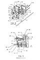
- a trip actuator In order to operate on the secondary latch 23 directly, a trip actuator, generally indicated at 27, is arranged within the second compartment 13 such that a mechanical actuator 29, including a first pivotally mounted lever 30 and a second lever 31, is arranged within the first compartment 12 while a magnetic module 28, a torsion spring 33 and a magnetic latchpiece 32 are arranged within the second compartment 13.
- An end 30A of the first lever 30 is arranged for interaction with a tab 71 on the secondary latch 23, while the second lever 31 engages the torsion spring 33 by means of a protrusion 35 integrally formed on the second lever 31 for biasing the spring 33 against a stop 34 integrally formed on the exterior of the magnetic module 28, as seen by referring to Figure 5.
- the entire trip actuator 27 is shown disassembled in Figure 2 to illustrate the magnetic module 28 with its L-shaped stator 53 arranged with a vertical leg 54, as defined in the plane of Figure 2, carrying an integrally formed horizontal leg 55 around which are arranged a shunt trip coil 57 and a flux shift coil 58.
- the shunt trip coil 57 responds to an electronic trip signal to cause the circuit breaker operating mechanism to respond and open the contacts for remote switching purposes.
- the flux shift coil 58 is connected with an electronic trip unit 72 which comprises an integrated circuit trip unit 72 depicted in Figure 5. Upon the occurrence of an overcurrent condition through the protected circuit, an appropriate signal is sent to the flux shift coil to articulate the operating mechanism and trip the breaker.
- a rotor 59 consisting of an integrally upright arm having a downwardly extending leg member 63 and a radially formed protrusion 87, is pivotally mounted by means of a through-hole 61 extending through the rotor 59 for rotation about a pivot provided by headed bolt 50 used for assembling side frames 48, 49.
- a miniature permanent magnet 56 is imbedded within the vertical leg 54 for magnetic interaction with a rounded end 64 of the horizontal leg 55 by flux transfer through the upright arm 66 and thence the leg 63 of the rotor 59.
- the side frames 48, 49 of the magnetic module are attached together by means of the headed bolts 50 extending through clearance holes 51 formed on side frame 49, through clearance holes 60 formed within the L-shaped stator 53 and terminating within threaded holes 52 formed within the side frame 48.
- the torsion spring 33 is arranged on side frame 48 by means of a stud 9 located between stop 34 on the side frame and a protrusion 35 extending from the second lever 31.
- the magnetic latch accordingly comprises a hook-shaped latch-piece 65, pivotally attached to the upright arm 66 by means of the through-hole 61 for rotatably engaging a crosspiece 47 supported by integrally formed posts 45, 46 extending from a bar 44 integrally formed within the mechanical actuator 29.
- the mechanical actuator 29 accordingly comprises the first lever 30 and second lever 31 integrally formed from a single molded plastic operation and separated from each other by means of a connecting piece 81, which forms a part of the bar 44.
- the mechanical actuator 29 is supported on the magnetic module 28 by inserting the bar 44 integrally formed therein within the slot 94 formed in the bottom of the side frame 48.
- a similar slot 94 is arranged through the bottom of the other side frame 49 for supporting the opposite end of bar 44.
- the magnetic flux is carried through the rotor 59 from the point of contact on the upright arm down through the leg 63 to the rounded end 64 of the horizontal leg 55 formed on the L-shaped stator 53 to complete the magnetic path back to the miniature permanent magnet 56.
- the rounded end 64 ensures a single point of contact in a manner similar to the radial surface 67.
- a small trip spring 88 is secured to one end of leg 63 by means of a hole 89 and is attached to the outer cover (not shown) of the magnetic module 28 by means of a hooked end 90.
- the magnetic flux from the miniature permanent magnet 56 holds the rotor 59 from rotating in a clockwise direction against the bias of the trip spring 88.
- the torsion spring 33 is fixedly held against the stop 34 on the trip actuator 27 at one leg, as described earlier with reference to Figure 1, while the opposite leg abuts against the protrusion 35 on the second lever 31.
- the torsion spring 33 exhibits a force F1 in the indicated direction on the second lever 31, resulting in a first torque (F1)(X1) on the second lever rotating the lever about its pivot P measured at a distance X1 from the pivot P.
- the torsion spring 33 When the magnetic latch releases, thereby allowing the first and second levers 30, 31 to rotate in the counterclockwise direction about the pivot P, the torsion spring 33 exhibits a force F2 in the indicated direction which slightly decreases in magnitude as the torsion spring 33 proceeds to move from the magnetically latched to the magnetically unlatched position indicated in solid lines.
- F2 is applied at a second distance X2 from the pivot P to produce a torque (F2)(X2), which is substantially greater than the first torque.
- the increase in torque results primarily from the increase in the length of the distance X2 over the distance X1.
- the resultant force delivered to the extension 71 of the secondary latch 23 correspondingly increases in magnitude, moving from the magnetically latched to the magnetically unlatched position.
- the arrangement of the first and second levers 30, 31 at predetermined distances X1, X2 is an important feature of the instant invention. This arrangement provides a small "latching" force of a few ounces in magnitude against the second lever that is much lower than the available magnetic force generated by the miniature permanent magnet 56 ( Figure 3), while providing a resulting tripping force on the secondary latch extension in the order of several pounds. The larger tripping force is required to overcome the circuit breaker latching forces which are applied to the secondary latch extension 71 within the circuit breaker operating mechanism 15 shown in Figure 1.
- the two-pole breaker 10 is shown in Figure 5 with the cover removed and with the electronic components assembled for providing the necessary trip logic to the magnetic module 28.
- the current applied to the load side of the breaker overload straps 79, 81 is sensed through both poles by means of current transformers 73, 74, which include cores 76, 76 and secondary windings 77 and 78 respectively.
- the sensed current from the secondary windings is directed from terminal pins 84 and wires 85 to corresponding terminals 68 on the integrated circuit trip unit 72 for processing.
- the wires 85 interconnect between the two poles through an access slot 91 formed within the center wall 14 of the breaker case 11.
- an output signal from the trip unit is fed to the magnetic module 28, which is interconnected with the trip unit by means of terminals 68.
- the mechanical actuator assembly 29 is arranged within the circuit breaker case 11 such that the end 82 of the integrally formed bar 44 is rotatably supported within an opening 83 formed in the magnetic module enclosure 92 at one end, while being rotatably supported at an opposite end by the connecting piece 81 which nests in a corresponding opening 93 formed in the opposite end of the enclosure.
- the magnetic module 28 Upon receiving a trip signal from the trip unit, the magnetic module 28 releases the hook-shaped latch-piece 65 from crosspiece 47 on the mechanical actuator 29, thereby allowing the torsion spring 33 abutting against the protrusion 35 on the second lever 31 to drive the lever counterclockwise as viewed in Figure 4, thereby rotating the first lever 30 and driving the contact end 30A against a trip tab 71, which is an extension of the circuit breaker secondary latch 23.
- the secondary latch 23 then becomes displaced thereby allowing a boss 70 on the secondary latch 23 to move out of the path of the primary latch 24, sequentially allowing the cradle hook 25 to become released from the primary latch 24.
- the cradle 20 rapidly rotates in the manner described within the referenced U.S.
- Patent Application to allow the operating circuit breaker operating springs shown therein to separate the contacts and interrupt the circuit current. Still referring to Figure 5, the breaker is reset by engaging the cradle hook 25 with the primary latch 24, bringing the secondary latch 23 and the trip tab 71 on the secondary latch 23 against the contact end 30A of the primary lever 30 and rotating the primary lever from the position indicated in solid lines in Figure 4 to the latched position indicated in phantom.
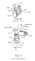
- FIG. 6 An alternate mechanical actuator 29 formed from a single molded plastic composition is depicted in Figure 6, wherein the second lever 31 is located in the same plane as the primary lever 30 but is offset a slight distance d ( Figure 7) from a center line through the center of the primary lever to enable the torsion spring 33 to rotate the actuator about its pivot P.
- the magnetic latch 32 is similar to that described earlier and comprises a pair of posts 45, 46 extending from a bar 44 and connected by means of a crosspiece 47.
- the torsion spring 33 contacts the second lever 31 by means of a hooked-end 37A and is anchored to the enclosure (not shown) at its opposite end 31B.
- the torsion spring exhibits a first force F1 in the indicated direction on the second lever and generates a torque at a first distance X1 measured from the pivot P.
- This first force F1 comprises the latching force described earlier.
- the torsion spring exerts a force F2 in the indicated direction, which provides a torque on the second lever 31 at a distance X2 from the pivot P.
- a trip actuator comprised of a unitary mechanical actuator and a magnetic module efficiently transfers the electronic trip logic from an electronic trip unit to mechanical motion for articulating a circuit breaker operating mechanism when arranged within a molded case circuit breaker enclosure.
- the arrangement of the trip actuator in an outside pole compartment of a multi-pole breaker prevents dielectric failure between the poles.
- the particular arrangement of a torsion spring and mechanical actuator results in a high spring force with a low torque on the mechanical actuator in a magnetically latched position and a low spring force with a high torque applied to the mechanical actuator when the magnetic module is magnetically unlatched.
- the arrangement of the torsion spring and mechanical actuator advantageously allows the mechanical actuator to be reset against a decreasing reset force.
Landscapes
- Physics & Mathematics (AREA)
- Electromagnetism (AREA)
- Breakers (AREA)
Abstract
Description
- Electronic trip unit circuits fabricated by V.L.S.I. very large scale integration techniques, such as described within U.S. Patent 4,589,052 to John Dougherty, entitled "Digital I²T Pick-Up, Time Bands and Timing Control Static Trip Circuit Breaker", have substantially reduced the size requirements for such electronic trip circuits. The development of laminated core current sensing transformers, such as described within U.S. Patent 4,591,942 to Henry Willard et al, entitled "Current Sensing Transformer Assembly", substantially reduces the cost of high quality current sensing transformers, making such current sensing transformers economically feasible within lower ampere rated industrial molded case circuit breakers. The reduction in size of both the trip unit and current sensing transformers allows the combination to be used within a common molded case industrial circuit breaker housing.
- Besides providing a wide range of time over current trip characteristics, electronic trip units further provide accessory functions. Such functions include shunt trip and undervoltage as well as zone-select interlock facility, which heretofore was provided to themal-magnetic industrial molded case circuit breakers of lower ampere rating by separate individual accessory units.
- When such electronic trip units are employed with common circuit breaker operating mechanisms, a trip force must be provided to overcome the mechanical latching forces that exist between the circuit breaker cradle and the primary latch as well as between the primary and secondary latches themselves. The latching force requirements ensure resistance against so-called "nuisance tripping" due to external environmental effects, such as shock and vibration. To overcome these latching forces, a powerful trip force is usually supplied by an electro-magnetic armature held against the forward bias of a relatively heavy compression spring by the attraction of a permanent magnet. An electric current pulse to the electromagnet opposes the magnetic force of attraction and allows the armature to be driven forward under the bias of the compression spring to articulate the operating mechanism and open the breaker contacts. Since the size requirement of the permanent magnet, compression spring and the electromagnet are gauged in proportion to the latching forces, such size requirements have heretofore prevented magnetic trip actuators from being economically feasible in industrial rated molded case circuit breakers of lower ampere ratings.
- The present invention provides sufficient trip force to overcome the circuit breaker latching forces by the cooperative arrangement of a compact magnetic latch and a mechanical actuator. The mechanical actuator design converts a low latching force from the magnetic latch to a high tripping force at the circuit breaker trip mechanism. The low force requirements result in the use of a compact electronic trip unit, sensing transformers and accessories within a compact molded case.
- An electronically driven trip actuator comprised of a magnetic latch and a molded plastic mechanical actuator allows the use of an electronic trip unit within lower ampere rated industrial molded case circuit breakers. The magnetic latch assembly comprises a hook-shaped latch-piece, stator and rotor pivotally arranged relative to a miniature permanent magnet. The mechanical actuator comprises a single molded plastic structure which includes a first lever in contact with the circuit breaker latch and a second lever in contact with a torsion spring. A crosspiece integrally formed within the mechanical actuator is held against the urgence of the torsion spring bias by engagement with the latch-piece of the magnetic latch assembly.
-
- Figure 1 is a top perspective view, in isometric projection, of a two pole molded case circuit breaker including the trip actuator according to the invention;
- Figure 2 is a top perspective view, in isometric projection, of the components within the trip actuator depicted in Figure 1;
- Figure 3 is a side view of the assembled trip actuator depicted in Figures 1 and 2;
- Figure 4 is a side view of the mechanical actuator depicted in Figures 1 and 2;
- Figure 5 is a plan view of the circuit breaker of Figure 1 after assembly of the breaker components;
- Figure 6 is a top perspective view of an alternate mechanical trip actuator used within the trip actuator according to the invention; and
- Figure 7 is a side view of the alternate mechanical actuator depicted in Figure 6.
- An industrial rated molded
case circuit breaker 10 having an ampere rating of 15 to 1,200 amperes is depicted at 10 in Figure 1, wherein a molded plastic case 11 is arranged in a two-pole configuration with a first compartment 12 and a second compartment 13 integrally formed with the case and separated from each other by means of a dividingwall 14. Anoperating mechanism 15 of the type described in U.S. Patent Application serial number 817,213, filed January 8, 1986, entitled "Interchangeable Mechanism For Molded Case Circuit Breaker", is mounted in the first compartment over acontact arm carrier 17 which supports amovable contact arm 16. The completely assembled circuit breaker includes a fixed contact arm and means for electrical interconnection with an external circuit and, although not shown, is completely described within the referenced U.S. Patent Application which should be reviewed for a better understanding thereof. Themovable contact arm 16 extends within anarc chamber 18, which contains means for extinguishing an arc that occurs when the circuit breaker contacts are separated to interrupt the current through a protected circuit. The arc chute arrangement is also found within the aforementioned U.S. Patent Application. A similar contact arm and contact arm carrier are arranged within the second compartment 13 and are interconnected with the firstmovable contact arm 16 andcontact arm carrier 17 by means of a crossbar 86, which extends between both compartments 12, 13 through acrossbar slot 41. When completely assembled, both contact arms move in unison under the operation of a circuit breaker handle 39 mounted to theoperating mechanism 15 by means of ahandle yoke assembly 38. The operating mechanism is assembled between a pair of side frames 19A, 19B, which carries anoperating cradle 20 for latching the breaker contacts in a closed condition by the engagement of acradle hook 25 with a primary latch 24 and also by means of asecondary latch 23 mounted to the operating mechanism by means of asecondary latch pivot 69. Theentire latch assembly 22, consisting of the primary and secondary latches as described within the referenced U.S. Patent Application, further includes atrip bar 26 pivotally arranged for moving thesecondary latch 23 away from the primary latch 24 to thereby allow the cradle to be released by the primary latch and move the movable contacts into an open position. Thehandle 39 protrudes through aslot 37 arranged through the moldedcover 36, which is securely attached to the molded case 11 by means of screws or rivets (not shown). In order to operate on thesecondary latch 23 directly, a trip actuator, generally indicated at 27, is arranged within the second compartment 13 such that amechanical actuator 29, including a first pivotally mountedlever 30 and asecond lever 31, is arranged within the first compartment 12 while amagnetic module 28, atorsion spring 33 and amagnetic latchpiece 32 are arranged within the second compartment 13. Anend 30A of thefirst lever 30 is arranged for interaction with atab 71 on thesecondary latch 23, while thesecond lever 31 engages thetorsion spring 33 by means of aprotrusion 35 integrally formed on thesecond lever 31 for biasing thespring 33 against astop 34 integrally formed on the exterior of themagnetic module 28, as seen by referring to Figure 5. Electrical connection with the magnetic module components is made by a plurality ofterminals 68 arranged on the exterior of the magnetic module. Electrical integrity between both poles is assured by theslots corresponding slots cover 36, which allow the crossbar 86 and thefirst operating lever 30 to extend within the first compartment 12 without allowing any electrical access between the electrical components within both poles. - The
entire trip actuator 27 is shown disassembled in Figure 2 to illustrate themagnetic module 28 with its L-shaped stator 53 arranged with avertical leg 54, as defined in the plane of Figure 2, carrying an integrally formedhorizontal leg 55 around which are arranged ashunt trip coil 57 and aflux shift coil 58. Theshunt trip coil 57 responds to an electronic trip signal to cause the circuit breaker operating mechanism to respond and open the contacts for remote switching purposes. Theflux shift coil 58 is connected with anelectronic trip unit 72 which comprises an integratedcircuit trip unit 72 depicted in Figure 5. Upon the occurrence of an overcurrent condition through the protected circuit, an appropriate signal is sent to the flux shift coil to articulate the operating mechanism and trip the breaker. Arotor 59, consisting of an integrally upright arm having a downwardly extendingleg member 63 and a radially formedprotrusion 87, is pivotally mounted by means of a through-hole 61 extending through therotor 59 for rotation about a pivot provided byheaded bolt 50 used for assemblingside frames permanent magnet 56 is imbedded within thevertical leg 54 for magnetic interaction with arounded end 64 of thehorizontal leg 55 by flux transfer through theupright arm 66 and thence theleg 63 of therotor 59. Theside frames headed bolts 50 extending throughclearance holes 51 formed onside frame 49, throughclearance holes 60 formed within the L-shaped stator 53 and terminating within threadedholes 52 formed within theside frame 48. Thetorsion spring 33 is arranged onside frame 48 by means of astud 9 located betweenstop 34 on the side frame and aprotrusion 35 extending from thesecond lever 31. The magnetic latch accordingly comprises a hook-shaped latch-piece 65, pivotally attached to theupright arm 66 by means of the through-hole 61 for rotatably engaging acrosspiece 47 supported by integrally formedposts bar 44 integrally formed within themechanical actuator 29. Themechanical actuator 29 accordingly comprises thefirst lever 30 andsecond lever 31 integrally formed from a single molded plastic operation and separated from each other by means of a connectingpiece 81, which forms a part of thebar 44. Themechanical actuator 29 is supported on themagnetic module 28 by inserting thebar 44 integrally formed therein within theslot 94 formed in the bottom of theside frame 48. Asimilar slot 94 is arranged through the bottom of theother side frame 49 for supporting the opposite end ofbar 44. - The operation of the
magnetic module 28 is now seen by referring to Figure 3 wherein the module is depicted in solid lines magnetically latched by the capture of thecrosspiece 47 under the end of the hook-shaped latch-piece 65 and is depicted in phantom in an unlatched condition. Theradial surface 67 on theupright arm 66 of therotor 59 abuts the miniaturepermanent magnet 56 at only one point of contact. This singular contact point is effected by the geometry of theradial surface 67 such that the magnetic attraction of either side of the point of contact is evenly distributed. The magnetic flux is carried through therotor 59 from the point of contact on the upright arm down through theleg 63 to therounded end 64 of thehorizontal leg 55 formed on the L-shaped stator 53 to complete the magnetic path back to the miniaturepermanent magnet 56. Therounded end 64 ensures a single point of contact in a manner similar to theradial surface 67. Asmall trip spring 88 is secured to one end ofleg 63 by means of ahole 89 and is attached to the outer cover (not shown) of themagnetic module 28 by means of a hookedend 90. The magnetic flux from the miniaturepermanent magnet 56 holds therotor 59 from rotating in a clockwise direction against the bias of thetrip spring 88. When a signal is applied to theflux shift coil 58, the magnetic field induced therein opposes the flux produced within thehorizontal leg 55 by the permanent magnet, thereby allowing therotor 59 to rotate and carry theradial protrusion 87 into contact with the hook-shaped latch-piece driving the hook-shaped latch-piece 65 to the position indicated in phantom and allowing thecrosspiece 47 to move forward under the influence of thetorsion spring 33, as best seen by referring now to Figure 4. - The
torsion spring 33 is fixedly held against thestop 34 on thetrip actuator 27 at one leg, as described earlier with reference to Figure 1, while the opposite leg abuts against theprotrusion 35 on thesecond lever 31. When thetrip actuator 27 is in the latched position, as indicated in phantom in Figure 4, thetorsion spring 33 exhibits a force F₁ in the indicated direction on thesecond lever 31, resulting in a first torque (F₁)(X₁) on the second lever rotating the lever about its pivot P measured at a distance X₁ from the pivot P. When the magnetic latch releases, thereby allowing the first andsecond levers torsion spring 33 exhibits a force F₂ in the indicated direction which slightly decreases in magnitude as thetorsion spring 33 proceeds to move from the magnetically latched to the magnetically unlatched position indicated in solid lines. F₂ is applied at a second distance X₂ from the pivot P to produce a torque (F₂)(X₂), which is substantially greater than the first torque. The increase in torque results primarily from the increase in the length of the distance X₂ over the distance X₁. The resultant force delivered to theextension 71 of thesecondary latch 23 correspondingly increases in magnitude, moving from the magnetically latched to the magnetically unlatched position. The arrangement of the first andsecond levers secondary latch extension 71 within the circuitbreaker operating mechanism 15 shown in Figure 1. - The two-
pole breaker 10 is shown in Figure 5 with the cover removed and with the electronic components assembled for providing the necessary trip logic to themagnetic module 28. The current applied to the load side of the breaker overload straps 79, 81 is sensed through both poles by means ofcurrent transformers cores secondary windings terminal pins 84 andwires 85 to correspondingterminals 68 on the integratedcircuit trip unit 72 for processing. Thewires 85 interconnect between the two poles through anaccess slot 91 formed within thecenter wall 14 of the breaker case 11. Upon determination of an overload condition, an output signal from the trip unit is fed to themagnetic module 28, which is interconnected with the trip unit by means ofterminals 68. Themechanical actuator assembly 29 is arranged within the circuit breaker case 11 such that theend 82 of the integrally formedbar 44 is rotatably supported within anopening 83 formed in themagnetic module enclosure 92 at one end, while being rotatably supported at an opposite end by the connectingpiece 81 which nests in acorresponding opening 93 formed in the opposite end of the enclosure. Upon receiving a trip signal from the trip unit, themagnetic module 28 releases the hook-shaped latch-piece 65 fromcrosspiece 47 on themechanical actuator 29, thereby allowing thetorsion spring 33 abutting against theprotrusion 35 on thesecond lever 31 to drive the lever counterclockwise as viewed in Figure 4, thereby rotating thefirst lever 30 and driving thecontact end 30A against atrip tab 71, which is an extension of the circuit breakersecondary latch 23. Thesecondary latch 23 then becomes displaced thereby allowing aboss 70 on thesecondary latch 23 to move out of the path of the primary latch 24, sequentially allowing thecradle hook 25 to become released from the primary latch 24. Thecradle 20 rapidly rotates in the manner described within the referenced U.S. Patent Application to allow the operating circuit breaker operating springs shown therein to separate the contacts and interrupt the circuit current. Still referring to Figure 5, the breaker is reset by engaging thecradle hook 25 with the primary latch 24, bringing thesecondary latch 23 and thetrip tab 71 on thesecondary latch 23 against thecontact end 30A of theprimary lever 30 and rotating the primary lever from the position indicated in solid lines in Figure 4 to the latched position indicated in phantom. - An alternate
mechanical actuator 29 formed from a single molded plastic composition is depicted in Figure 6, wherein thesecond lever 31 is located in the same plane as theprimary lever 30 but is offset a slight distance d (Figure 7) from a center line through the center of the primary lever to enable thetorsion spring 33 to rotate the actuator about its pivot P. Themagnetic latch 32 is similar to that described earlier and comprises a pair ofposts bar 44 and connected by means of acrosspiece 47. - Referring now to Figure 7, the
torsion spring 33 contacts thesecond lever 31 by means of a hooked-end 37A and is anchored to the enclosure (not shown) at its opposite end 31B. In a similar manner as shown earlier with reference to Figure 4, the torsion spring exhibits a first force F₁ in the indicated direction on the second lever and generates a torque at a first distance X₁ measured from the pivot P. This first force F₁ comprises the latching force described earlier. When the trip actuator becomes unlatched, the torsion spring exerts a force F₂ in the indicated direction, which provides a torque on thesecond lever 31 at a distance X₂ from the pivot P. When thecontact end 30A of thefirst lever 31 rotates into contact with thetrip tab 71, a force of several pounds is generated in the movement of theprimary lever 30 from the latched to the unlatched position. It is noted that thetorsion spring 33 also moves with thesecond lever 31 and substantially reduces any friction forces which would otherwise exist between the spring end 37A and thesecond lever 31 if thetorsion spring 33 should remain motionless. The low friction arrangement between the torsion spring and the second lever is an important feature of this trip actuator design, since it allows this trip actuator to rotate at a faster rate than the one depicted in Figure 4. - It has thus been shown that a trip actuator comprised of a unitary mechanical actuator and a magnetic module efficiently transfers the electronic trip logic from an electronic trip unit to mechanical motion for articulating a circuit breaker operating mechanism when arranged within a molded case circuit breaker enclosure. The arrangement of the trip actuator in an outside pole compartment of a multi-pole breaker prevents dielectric failure between the poles. The particular arrangement of a torsion spring and mechanical actuator results in a high spring force with a low torque on the mechanical actuator in a magnetically latched position and a low spring force with a high torque applied to the mechanical actuator when the magnetic module is magnetically unlatched. This results in the application of an increasing tripping force against the secondary latch to articulate the circuit breaker operating mechanism. After the circuit breaker mechanism has tripped, the arrangement of the torsion spring and mechanical actuator advantageously allows the mechanical actuator to be reset against a decreasing reset force.
- Having thus described our invention, what we claim as new and desire to secure by Letters Patent is:
Claims (19)
an insulative case containing a pair of separable contacts operatively connected with an operating mechanism for opening and closing said contacts;
a circuit breaker latch at a first location within said mechanism for holding said contacts closed against the bias of an over-center operating spring;
a trip actuator comprising a first and a second lever arranged for rotation about a common pivot under the urgence of an actuator spring, said first lever arranged for contacting said circuit breaker latch to displace said circuit breaker latch to a second location thereby articulating said operating mechanism and causing said contacts to open under urgence of said operating spring, said second lever abutting said actuator spring;
a crosspiece attached to said first and second levers for engagement with a latch-piece to retain said first and second levers from rotation against the bias of said actuator springs; and
a magnetic module operatively connected with said latch-piece for moving said latch-piece out of engagement with said crosspiece thereby allowing said first and second levers to rotate under the urgence of said actuator spring.
said actuator spring generates a second force on said first and second levers at a second distance from said pivot to provide a second torque on said trip actuator, said second torque being greater than said first torque to accelerate rotation of said trip actuator into contact with said circuit breaker latch.
a partitioned molded plastic case comprising a first and a second compartment including first and second pairs of separable contacts under control of a common operating mechanism;
a partitioned molded plastic cover comprising complementary first and second compartments for overlaying said first and second case compartments;
a pair of current sensing transformers one in each of said first and second case compartments for electrical connection with an external protected circuit;
an electronic trip unit connected with said current transformers for determining an overcurrent condition through said protected circuit and providing a trip output signal upon occurrance of said overcurrent;
a trip actuator within said first compartment and having an operating lever extending within said second compartment for articulating said operating mechanism to open said first and second pairs of separable contacts upon occurrance of said overcurrent;
a magnetic module within said first compartment comprising a rotor and stator, said stator including a permanent magnet attached thereto, said rotor being retained from rotation against the bias of a trip spring by abutment with said stator and by influence of magnetic flux generated by said permanent magnet, said stator further including an electric trip coil arranged around a first leg; and
said trip actuator operating lever being retained from rotating against the bias of an actuator spring by contact between a crosspiece on said operating lever and a latch-piece on said magnetic module, said latch-piece being arranged for contact with said stator when said trip output signal is applied to said electric coil whereby said electric coil generates an opposing magnetic flux within said stator first leg to cancel said permanent magnet magnetic flux thereby allowing said rotor to move said latch-piece out of contact with said crosspiece.
a mechanical actuator having first and second lever arms arranged for rotation about a common pivot;
an actuator spring having a central body portion terminating in a first and a second leg, said second leg being retained against a fixed stop and said first leg contacting said second lever for rotating said trip actuator about said pivot;
a crosspiece attached to said mechanical actuator for retaining said mechanical actuator against rotation by said actuator spring;
a magnetic module comprising a fixed metallic L-shaped stator having first and second orthogonal legs with a permanent magnet attached to said first leg and an electromagnetic coil arranged around said second leg, a magnetic L-shaped rotor having first and second orthogonal legs pivotally arranged for rotation against the bias of a trip spring attached to said rotor second leg, said rotor first leg abutting said permanent magnet for providing a magnetic force on said rotor to retain said rotor from rotation against the bias of said trip spring; and
a hook-shaped latch-piece rotatably mounted on said magnetic module and arranged for engaging said crosspiece, said latch-piece being rotated away from said crosspiece to release said mechanical actuator and allow said mechanical actuator to rotate under the urgence of said actuator spring when a current pulse is applied to said electromagnetic coil to induce a magnetic force within said stator second leg in opposition to said permanent magnet magnetic force and thereby allow said rotor to rotate under the urgence of said trip spring.
Applications Claiming Priority (2)
| Application Number | Priority Date | Filing Date | Title |
|---|---|---|---|
| US862929 | 1986-05-14 | ||
| US06/862,929 US4679019A (en) | 1986-05-14 | 1986-05-14 | Trip actuator for molded case circuit breakers |
Publications (2)
| Publication Number | Publication Date |
|---|---|
| EP0245834A2 true EP0245834A2 (en) | 1987-11-19 |
| EP0245834A3 EP0245834A3 (en) | 1989-10-18 |
Family
ID=25339763
Family Applications (1)
| Application Number | Title | Priority Date | Filing Date |
|---|---|---|---|
| EP87106853A Withdrawn EP0245834A3 (en) | 1986-05-14 | 1987-05-12 | Trip actuator for molded case circuit breaker |
Country Status (3)
| Country | Link |
|---|---|
| US (1) | US4679019A (en) |
| EP (1) | EP0245834A3 (en) |
| JP (1) | JPS62272420A (en) |
Cited By (2)
| Publication number | Priority date | Publication date | Assignee | Title |
|---|---|---|---|---|
| FR2633772A1 (en) * | 1988-04-11 | 1990-01-05 | Gen Electric | CIRCUIT BREAKER HANDLE IN MOLDED HOUSING FOR AUTOMATED ASSEMBLY |
| FR2640423A1 (en) * | 1988-12-14 | 1990-06-15 | Merlin Gerin | CONTROL MECHANISM OF A MULTIPOLAR DIFFERENTIAL SWITCH WITH ROTATING SWITCHING BAR |
Families Citing this family (59)
| Publication number | Priority date | Publication date | Assignee | Title |
|---|---|---|---|---|
| US4835842A (en) * | 1987-04-23 | 1989-06-06 | General Electric Company | Method of assembling a molded case circuit breaker operating mechanism |
| US4801906A (en) * | 1987-10-19 | 1989-01-31 | General Electric Company | Molded case circuit breaker trip indicator unit |
| US4786885A (en) * | 1987-12-16 | 1988-11-22 | General Electric Company | Molded case circuit breaker shunt trip unit |
| US4794356A (en) * | 1987-12-16 | 1988-12-27 | General Electric Company | Molded case circuit breaker auxiliary switch unit |
| US4831221A (en) * | 1987-12-16 | 1989-05-16 | General Electric Company | Molded case circuit breaker auxiliary switch unit |
| US4788621A (en) * | 1987-12-16 | 1988-11-29 | General Electric Company | Molded case circuit breaker multiple accessory unit |
| US4806893A (en) * | 1988-03-03 | 1989-02-21 | General Electric Company | Molded case circuit breaker actuator-accessory unit |
| US4833563A (en) * | 1988-04-01 | 1989-05-23 | General Electric Company | Molded case circuit breaker actuator-accessory module |
| US4860157A (en) * | 1988-04-25 | 1989-08-22 | General Electric Company | Molded case circuit breaker actuator-accessory module |
| US4858056A (en) * | 1988-06-06 | 1989-08-15 | General Electric Company | Molded case circuit breaker actuator-accessory module |
| US4890081A (en) * | 1988-08-01 | 1989-12-26 | Westinghouse Electric Corp. | CT quick change assembly |
| US4894631A (en) * | 1988-09-06 | 1990-01-16 | General Electric Company | Molded case circuit breaker actuator-accessory unit |
| US4913503A (en) * | 1988-10-07 | 1990-04-03 | General Electric Company | Molded case circuit breaker actuator-accessory unit reset mechanism |
| US4890184A (en) * | 1988-12-30 | 1989-12-26 | Gen Electric | Molded case circuit breaker actuator-accessory unit |
| US4912439A (en) * | 1989-01-27 | 1990-03-27 | General Electric Company | Molded case circuit breaker auxiliary switch unit |
| US4884164A (en) * | 1989-02-01 | 1989-11-28 | General Electric Company | Molded case electronic circuit interrupter |
| US4939490A (en) * | 1989-02-17 | 1990-07-03 | General Electric Company | Molded case circuit breaker bell alarm unit |
| US4929920A (en) * | 1989-06-23 | 1990-05-29 | General Electric Company | Compact circuit breaker with an electronic trip unit |
| US5252937A (en) * | 1990-08-09 | 1993-10-12 | General Electric Company | Molded case circuit breaker modular bell alarm unit |
| US5059933A (en) * | 1990-09-14 | 1991-10-22 | General Electric Company | Molded case circuit breaker operating cradle configuration |
| US5027093A (en) * | 1990-10-29 | 1991-06-25 | General Electric Company | Molded case circuit breaker actuator-accessory unit having component tolerance compensation |
| US5295037A (en) * | 1992-01-27 | 1994-03-15 | General Electric Company | Molded case circuit breaker-process loop unit |
| US5321378A (en) * | 1993-04-08 | 1994-06-14 | General Electric Company | Molded case circuit breaker current transformer adapter unit |
| US5710399A (en) * | 1996-05-01 | 1998-01-20 | General Electric Company | Electronic trip unit conversion kit for high ampere-rated circuit breakers |
| US5894260A (en) * | 1996-12-19 | 1999-04-13 | Siemens Energy & Automation, Inc. | Thermal sensing bi-metal trip actuator for a circuit breaker |
| US6087914A (en) * | 1996-12-19 | 2000-07-11 | Siemens Energy & Automation, Inc. | Circuit breaker combination thermal and magnetic trip actuator |
| US5844188A (en) * | 1996-12-19 | 1998-12-01 | Siemens Energy & Automation, Inc. | Circuit breaker with improved trip mechanism |
| US5866996A (en) * | 1996-12-19 | 1999-02-02 | Siemens Energy & Automation, Inc. | Contact arm with internal in-line spring |
| US6060674A (en) * | 1997-05-28 | 2000-05-09 | Eaton Corporation | Circuit interrupter with plasma arc acceleration chamber and contact arm housing |
| US5875885A (en) * | 1997-05-28 | 1999-03-02 | Eaton Corporation | Combined wire lead and interphase barrier for power switches |
| DE20109898U1 (en) * | 2001-06-13 | 2001-09-06 | Siemens AG, 80333 München | Low-voltage circuit breaker with an electronic overcurrent release and release magnet |
| US7106155B2 (en) * | 2004-12-21 | 2006-09-12 | Eaton Corporation | Double-lever mechanism, trip actuator assembly and electrical switching apparatus employing the same |
| JP4650023B2 (en) * | 2005-02-25 | 2011-03-16 | 富士電機機器制御株式会社 | Circuit breaker |
| TWI327794B (en) * | 2005-12-12 | 2010-07-21 | Hon Hai Prec Ind Co Ltd | Electrical connector |
| US7369022B2 (en) * | 2006-01-23 | 2008-05-06 | Eaton Corporation | Auxiliary switch sub-assembly and electrical switching apparatus employing the same |
| US7319373B2 (en) * | 2006-01-23 | 2008-01-15 | Eaton Corporation | Electrical switching apparatus and terminal housing therefor |
| US7843291B2 (en) | 2006-02-23 | 2010-11-30 | Siemens Industry, Inc. | Integrated maglatch accessory |
| CN101507060B (en) * | 2006-06-30 | 2011-08-10 | 莫列斯公司 | Low profile latching connector and pull tab for unlatching same |
| US7869169B2 (en) * | 2006-07-14 | 2011-01-11 | William Davison | Method and system of current transformer output magnitude compensation in a circuit breaker system |
| US7683586B2 (en) * | 2006-07-14 | 2010-03-23 | Davison William C | Method and system of fault powered supply voltage regulation |
| US8154373B2 (en) * | 2006-07-14 | 2012-04-10 | Schneider Electric USA, Inc. | Circuit breaker-like apparatus with combination current transformer |
| US7788055B2 (en) | 2006-07-14 | 2010-08-31 | Square D Company | Method and system of calibrating sensing components in a circuit breaker system |
| US7859802B2 (en) * | 2006-07-14 | 2010-12-28 | William Davison | Burden resistor temperature compensation algorithm |
| US7869170B2 (en) * | 2006-07-14 | 2011-01-11 | Susan Jean Walker Colsch | Method and system for time synchronized trip algorithms for breaker self protection |
| US7697250B2 (en) * | 2006-07-14 | 2010-04-13 | William Davison | Switch-to-trip point translation |
| US7592888B2 (en) * | 2006-07-14 | 2009-09-22 | Jason Robert Colsch | Low cost user adjustment, resistance to straying between positions, increased resistance to ESD, and consistent feel |
| US7791849B2 (en) * | 2006-07-14 | 2010-09-07 | William Davison | Redundant trip activation |
| US7550939B2 (en) * | 2006-07-14 | 2009-06-23 | William Davison | Redundant instantaneous trip detection |
| US7518476B2 (en) * | 2007-04-05 | 2009-04-14 | Eaton Corporation | Electrical switching apparatus and trip actuator reset assembly therefor |
| US7570139B2 (en) * | 2007-04-05 | 2009-08-04 | Eaton Corporation | Electrical switching apparatus, and trip actuator assembly and reset assembly therefor |
| FR2926392B1 (en) * | 2008-01-10 | 2009-12-18 | Schneider Electric Ind Sas | ELECTRONIC TRIGGER HOUSING FOR CIRCUIT BREAKER, ELECTRONIC TRIGGERING DEVICE, AND ASSEMBLY METHOD |
| GB0915379D0 (en) * | 2009-09-03 | 2009-10-07 | Deepstream Technologies Ltd | Miniature circuit breaker |
| CN101964285B (en) * | 2010-10-29 | 2013-04-17 | 天津市百利电气有限公司 | Circuit breaker with mechanical resettable flux converter |
| US9484163B2 (en) | 2014-02-06 | 2016-11-01 | Eaton Corporation | Disconnect operating handles suitable for circuit breakers and related bucket assemblies |
| US9496101B2 (en) | 2014-02-06 | 2016-11-15 | Eaton Corporation | Disconnect operating handles suitable for circuit breakers and related bucket assemblies and handle interlocks |
| CN106158529B (en) * | 2015-04-28 | 2018-10-23 | 上海电科电器科技有限公司 | The operating mechanism of breaker |
| US9406465B1 (en) * | 2015-07-30 | 2016-08-02 | Carling Technologies, Inc. | Polarity insensitive arc quench |
| US11417489B2 (en) * | 2020-06-03 | 2022-08-16 | Rockwell Automation Technologies, Inc. | Trip unit fixation in a circuit breaker |
| CN112401510B (en) * | 2020-10-26 | 2025-03-07 | 上海古鳌电子科技股份有限公司 | A filing cabinet |
Family Cites Families (7)
| Publication number | Priority date | Publication date | Assignee | Title |
|---|---|---|---|---|
| CH456769A (en) * | 1966-09-22 | 1968-07-31 | Landis & Gyr Ag | Electromagnetic trip relay |
| US3758887A (en) * | 1968-02-06 | 1973-09-11 | Westinghouse Electric Corp | Multi-pole circuit breaker with single trip adjustment for all poles |
| US3808567A (en) * | 1973-01-30 | 1974-04-30 | A Maier | Circuit breaker with improved resettable latch and trip means |
| US4104601A (en) * | 1976-04-12 | 1978-08-01 | I-T-E Imperial Corp. | Direct fault tripping of circuit breaker having solid state trip means |
| JPS56122246U (en) * | 1980-02-19 | 1981-09-17 | ||
| US4589942A (en) * | 1984-07-11 | 1986-05-20 | Transilwrap Company | Method for laminating a composite assembly |
| US4591942A (en) * | 1984-12-07 | 1986-05-27 | General Electric Company | Current sensing transformer assembly |
-
1986
- 1986-05-14 US US06/862,929 patent/US4679019A/en not_active Expired - Lifetime
-
1987
- 1987-03-16 JP JP62059125A patent/JPS62272420A/en active Pending
- 1987-05-12 EP EP87106853A patent/EP0245834A3/en not_active Withdrawn
Cited By (4)
| Publication number | Priority date | Publication date | Assignee | Title |
|---|---|---|---|---|
| FR2633772A1 (en) * | 1988-04-11 | 1990-01-05 | Gen Electric | CIRCUIT BREAKER HANDLE IN MOLDED HOUSING FOR AUTOMATED ASSEMBLY |
| FR2640423A1 (en) * | 1988-12-14 | 1990-06-15 | Merlin Gerin | CONTROL MECHANISM OF A MULTIPOLAR DIFFERENTIAL SWITCH WITH ROTATING SWITCHING BAR |
| EP0377385A1 (en) * | 1988-12-14 | 1990-07-11 | Merlin Gerin | Operating mechanism for a multiple fault-current protective switch with a rotary crossbar |
| EP0602024A3 (en) * | 1988-12-14 | 1994-09-14 | Merlin Gerin | Operating mechanism for a multipolar fault-current protective switch with a rotary crossbar. |
Also Published As
| Publication number | Publication date |
|---|---|
| JPS62272420A (en) | 1987-11-26 |
| EP0245834A3 (en) | 1989-10-18 |
| US4679019A (en) | 1987-07-07 |
Similar Documents
| Publication | Publication Date | Title |
|---|---|---|
| EP0245834A2 (en) | Trip actuator for molded case circuit breaker | |
| US4700161A (en) | Combined trip unit and accessory module for electronic trip circuit breakers | |
| US4281359A (en) | Static trip unit for molded case circuit breakers | |
| US5231365A (en) | Circuit breaker | |
| CA2105917C (en) | Attachment actuator arrangement for 1 and 2-pole ground fault | |
| US5581219A (en) | Circuit breaker | |
| US7598830B2 (en) | Electromagnetic coil apparatus employing a magnetic flux enhancer, and accessory and electrical switching apparatus employing the same | |
| US8159318B2 (en) | Electromagnet assembly directly driving latch of an electronic circuit breaker | |
| US4757294A (en) | Combined trip unit and accessory module for electronic trip circuit breakers | |
| US6853279B1 (en) | Circuit breaker trip unit including a plunger resetting a trip actuator mechanism and a trip bar | |
| US5907461A (en) | Molded case circuit breaker with ground fault protection and signaling switches | |
| EP1981054B1 (en) | Electrical switching apparatus accessory sub-assembly employing reversible coil frame, and accessory and electrical switching apparatus employing the same | |
| CA2292470C (en) | Multiple microswitch actuation mechanism | |
| US6175288B1 (en) | Supplemental trip unit for rotary circuit interrupters | |
| US3855502A (en) | Ground fault interrupter device | |
| US4300110A (en) | Trip interlock for static trip circuit breakers | |
| US4683451A (en) | Circuit breaker with trip delay magnetic circuit | |
| US3369202A (en) | Circuit breaker stack including auxiliary features | |
| US4037184A (en) | Lockout and cover interlock for circuit breaker | |
| US5015983A (en) | Compact circuit interrupter having multiple ampere ratings | |
| US4267539A (en) | Circuit breaker having a cam for external adjustment of its trip point | |
| CA2049223C (en) | Molded case circuit breaker actuator-accessory unit having component tolerance compensation | |
| GB2071915A (en) | Static trip unit and interlock for circuit breaker | |
| JP3194713B2 (en) | Undervoltage trip device for circuit breaker | |
| JP3226319B2 (en) | Remote control circuit breaker |
Legal Events
| Date | Code | Title | Description |
|---|---|---|---|
| PUAI | Public reference made under article 153(3) epc to a published international application that has entered the european phase |
Free format text: ORIGINAL CODE: 0009012 |
|
| AK | Designated contracting states |
Kind code of ref document: A2 Designated state(s): DE FR GB IT |
|
| PUAL | Search report despatched |
Free format text: ORIGINAL CODE: 0009013 |
|
| AK | Designated contracting states |
Kind code of ref document: A3 Designated state(s): DE FR GB IT |
|
| 17P | Request for examination filed |
Effective date: 19900322 |
|
| 17Q | First examination report despatched |
Effective date: 19920221 |
|
| STAA | Information on the status of an ep patent application or granted ep patent |
Free format text: STATUS: THE APPLICATION IS DEEMED TO BE WITHDRAWN |
|
| 18D | Application deemed to be withdrawn |
Effective date: 19930414 |
|
| RIN1 | Information on inventor provided before grant (corrected) |
Inventor name: TODARO, FRANK ANDREW Inventor name: CASTONGUAY, ROGER NEIL Inventor name: KRAJEWSKI, ALEXANDER ANTHONY Inventor name: MORRIS, ROBERT ALLAN |