EP0245615A2 - Deceleration and pressure sensitive proportioning valve with low deceleration responsiveness - Google Patents
Deceleration and pressure sensitive proportioning valve with low deceleration responsiveness Download PDFInfo
- Publication number
- EP0245615A2 EP0245615A2 EP87103890A EP87103890A EP0245615A2 EP 0245615 A2 EP0245615 A2 EP 0245615A2 EP 87103890 A EP87103890 A EP 87103890A EP 87103890 A EP87103890 A EP 87103890A EP 0245615 A2 EP0245615 A2 EP 0245615A2
- Authority
- EP
- European Patent Office
- Prior art keywords
- piston
- valve
- fluid
- channel
- proportioning valve
- Prior art date
- Legal status (The legal status is an assumption and is not a legal conclusion. Google has not performed a legal analysis and makes no representation as to the accuracy of the status listed.)
- Granted
Links
Images
Classifications
-
- B—PERFORMING OPERATIONS; TRANSPORTING
- B60—VEHICLES IN GENERAL
- B60T—VEHICLE BRAKE CONTROL SYSTEMS OR PARTS THEREOF; BRAKE CONTROL SYSTEMS OR PARTS THEREOF, IN GENERAL; ARRANGEMENT OF BRAKING ELEMENTS ON VEHICLES IN GENERAL; PORTABLE DEVICES FOR PREVENTING UNWANTED MOVEMENT OF VEHICLES; VEHICLE MODIFICATIONS TO FACILITATE COOLING OF BRAKES
- B60T8/00—Arrangements for adjusting wheel-braking force to meet varying vehicular or ground-surface conditions, e.g. limiting or varying distribution of braking force
- B60T8/26—Arrangements for adjusting wheel-braking force to meet varying vehicular or ground-surface conditions, e.g. limiting or varying distribution of braking force characterised by producing differential braking between front and rear wheels
- B60T8/28—Arrangements for adjusting wheel-braking force to meet varying vehicular or ground-surface conditions, e.g. limiting or varying distribution of braking force characterised by producing differential braking between front and rear wheels responsive to deceleration
- B60T8/282—Arrangements for adjusting wheel-braking force to meet varying vehicular or ground-surface conditions, e.g. limiting or varying distribution of braking force characterised by producing differential braking between front and rear wheels responsive to deceleration using ball and ramp
Definitions
- This invention relates to a deceleration and pressure sensitive proportioning valve for the brake system of a vehicle, the valve preventing the communication of excess pressure to the brakes when the vehicle is traveling on a low coefficient of friction roadway surface.
- Copending Patent Applications Nos. 649,244 and 738,116 disclose proportioning valve assemblies which may be disposed entirely within or without the body of the master cylinder, and provide for deceleration and pressure sensitive response in order to reduce fluid pressure communicated to the rear wheels. By reducing brake fluid pressure applied to the rear wheels in loaded and unloaded vehicle situations, appropriate braking pressures are communicated to the rear wheels in accordance with vehicle loading so that braking distance will be shortened and wheel lock-up and subsequent skidding is minimized.
- Copending Patent Application No. 799,219 illustrates an alternative embodiment which eliminates the need for a fluid-containing chamber or reservoir and provides a completely self-contained proportioning valve assembly.
- the present invention provides a solution for minimizing or eliminating wheel lock-up while the vehicle is traveling on a low coefficient of friction roadway surface, in addition to reducing displacement losses and improving replenishment of fluid to the assembly.
- the present invention provides a proportioning valve assembly which includes a housing having an inlet and an outlet, a first piston disposed in the housing and subject to inlet and outlet pressures so that the valve assembly provides a pressure at the outlet reduced from the pressure at the inlet, spring means biasing the first piston toward an end of the housing, a second piston disposed within the housing and movable relative to the first piston, the second piston having an interior cavity, resilient means acting on said second piston, poppet valve means disposed within an interior cavity of the second piston and extendable therefrom, a spring-biasing said poppet valve means toward the outlet, channel means for connecting said housing with a fluid-containing chamber or reservoir, second valve means disposed in said channel and including means for biasing seat closure means toward a valve seat, an inertia sensitive object engaging said second valve means, third valve means disposed within said channel and engaged by said second valve means, the inertia sensitive object disposed within the fluid-containing chamber and deceler
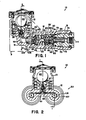
- FIGS 1-3 illustrate an embodiment of the proportioning valve assembly of the present invention and which is designated generally by the reference numeral 10.
- the proportioning valve assembly 10 may be contained within a housing 12 that is separate from the body of the master cylinder (not shown), and which has its own fluid-containing chamber or reservoir 13.
- Co-pending Patent Application No. 738,116 discloses a deceleration and pressure sensitive proportioning valve assembly which has high pressure damping and the Application is incorporated by reference herein.
- the proportioning valves 20 (see Figure 2) contained within the housing 12 are for a split braking circuit having a fluid pressure outlet 114 communicating with a rear wheel cylinder and another fluid pressure outlet (not shown) communicating with the other rear wheel cylinder.
- Figures 1 and 3 illustrate a bore 25 which communicates with the master cylinder (not shown) by means of passageway 33. Bore 25 communicates with a cavity 30 of channel 31 that communicates with the chamber 13, channel 31 including a stepped opening 32 comprising the opening of a second valve 34.
- Second valve 34 may comprise any one of numerous valve constructions which would function appropriately in the present invention, and herein comprises redundant serially aligned valves 160 and 170.
- An inertia sensitive ball 40 is located separate from the path of fluid flow through proportioning valve 20 and within chamber 13 on a variable slope ramp or surface 17. Inertia sensitive ball 40 holds second valve 34 open until a certain predetermined attitude is attained by the vehicle during deceleration or when deceleration displaces ball 40 up ramp 17.
- Bore 25 includes a reduced diameter portion 26 having therein a differential piston 70.
- Differential piston 70 includes through opening 72 providing for communication of outlet 114 with bore 25. Seals 73 are disposed about differential piston 70 which has valve seat 76 extending into bore 25 and with washer 62 disposed thereabout.
- a first spring 60 biases the washer 62 and differential piston 70 to the right in Figure 1, with one end of the spring 60 abutting bore shoulder 27.
- a second piston 80 comprises a longitudinal member having one end threadably received in and supporting enclosure 81 guided by washer extension 62a and the other reduced diameter end 82 extending into cavity 30 of channel 31. Enclosure 81 defines a cavity 83 which contains poppet 92 biased by spring 91 toward valve seat 76.
- the inertia sensitive ball 40 is disposed in a location that is separate from a fluid flow path leading from the master cylinder to the associated rear brakes. Thus, the inertia sensitive ball is not subject to fluid flow characteristics that occur within the fluid flow path during braking.
- Ball 40 is disposed on the variable slope surface or ramp 17 of valve body 36.
- the proportioning valves 20 illustrated in Figure 2 are connected together by channel 38.
- Valve body 36 includes the stepped opening 32 which communicates with channel 31.
- the body 36 includes threads 45 which are threadedly engaged with complementary threads of housing 12.
- O-ring seal 50 is disposed about body 36 in order to provide a seal between housing 12 and the body 36.
- Stepped opening 32 includes two valving members 160 and 170 in serial alignment with respective valve seats 64 and 74.
- Spring 59 is positioned on body 61 so as to bias valve member 160 toward ball valve 40 and into engagement with valve 170.
- Valve 170 is biased by spring 69 seated on valve member 160 so as to bias valve member 170 into engagement with ball 40.
- Body 61 includes an opening 63 and a valve seat 65 for third valve means 35.
- Valve means 35 comprises a ball valve which normally engages opening 63 so that when the valve is opened one-way flow is permitted only toward the chamber 13.
- Variable slope surface 17 may be either a compound surface as illustrated or a continuous variable slope surface.
- the initial low slope portion 39 provides for initial movement of the ball 40 before the ball engages the high slope portion 47.
- Valves 160 and 170 are the same as those illustrated in co-pending Patent Application No. 738,116, incorporated by reference herein.
- the serial alignment of the valves assure proper valving during operation of the proportioning valve assembly.
- the variable slope surface 17 is annular and permits multi-directional movement of ball 40 so that the ball is responsive vectorily both longitudinal deceleration and lateral deceleration of the vehicle.
- Seal 108 is positioned between washer 52 and sleeve 101, the reduced diameter end 82 of second piston 80 extending through an opening in washer 52 and the opening 103 of sleeve 101 to engage third piston 105.
- Third piston 105 has a cup seal 106 disposed about an end thereof, and is slidably disposed within sleeve 101. Compensating slots or grooves 107 are located in the end of third piston 105.
- An opening 90 provides for fluid compensation communication via grooves 91 disposed about the periphery of sleeve 101.
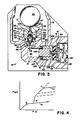
- Proportioning valves 20 contained within housing 12 operate as follows: Pressurized brake fluid received from inlet 33 passes through valve seat 76 and opening 72 to the associated outlet and to the wheel cylinder of a rear wheel brake. When the inlet pressure rises to a level sufficient to displace differential piston 70 to the left in Figure 1, valve seat 76 moves toward poppet end 93 to cause restriction of the brake fluid and pressure communicated through opening 72 to the rear wheel brake. This establishes a first brake point A, and if the vehicle is unloaded and traveling on a low coefficient of friction roadway surface such as ice, the brake pressure would proceed in accordance with curve A1 illustrated in Figure 4.
- third valve means 35 remains normally closed by ball 40, the provision of increasing braking pressures by the vehicle operator to valve assemblies 20 will not cause second piston 80 to move to the left and permit the higher braking braking pressure to be communicated to the rear brakes.
- Third piston 105 has a larger diameter than reduced diameter end 82 of second piston 80, and therefore, the low pressure in cavity 30 of channel 31 is sufficient to cause third piston 105 to remain stationary while third valve means 35 remains closed.
- wheel lock-up and subsequent skidding on a low coefficient of friction roadway surface such as ice is minimized or eliminated.
- the proportioning valve of the present invention includes the same inherent bypass system provided in the previously cited and incorporated patent application, wherein if one of the branches of the split circuit should fail, then there would be less deceleration of the vehicle and the second valve 34 in channel 31 would stay open so that a higher brake fluid pressure received from the master cylinder can be communicated to the associated brake cylinders.
- higher braking pressures can be communicated to the associated brake wheel cylinder to effect braking of the vehicle, and likewise for a system with a single proportioning valve.
- the proportioning valve assembly of the present invention provides for an improvement in the ability to prevent or minimize wheel lock-up while the vehicle is on low coefficient of friction roadway surfaces, substantially eliminates fluid displacement losses, and improves fluid replenishment of the cavity 30.
- second piston 80 will return toward the right in Figure 3, as will the third piston 105.
- variable slope surface 17 comprising initial low slope portion 39 and high slope portion 47 enables the ball 40 to move in response to deceleration experienced upon different coefficient of friction surfaces along which the vehicle is traveling. Because of small reduced diameter end 82 of second piston 80, there are smaller displacement losses in the braking system during operation.
Abstract
Description
- This invention relates to a deceleration and pressure sensitive proportioning valve for the brake system of a vehicle, the valve preventing the communication of excess pressure to the brakes when the vehicle is traveling on a low coefficient of friction roadway surface.
- Copending Patent Applications Nos. 649,244 and 738,116 disclose proportioning valve assemblies which may be disposed entirely within or without the body of the master cylinder, and provide for deceleration and pressure sensitive response in order to reduce fluid pressure communicated to the rear wheels. By reducing brake fluid pressure applied to the rear wheels in loaded and unloaded vehicle situations, appropriate braking pressures are communicated to the rear wheels in accordance with vehicle loading so that braking distance will be shortened and wheel lock-up and subsequent skidding is minimized. Copending Patent Application No. 799,219 illustrates an alternative embodiment which eliminates the need for a fluid-containing chamber or reservoir and provides a completely self-contained proportioning valve assembly.
- It is desirable to provide a deceleration and pressure sensitive proportioning valve assembly which also prevents the communication of excess fluid pressure to the rear brakes while the vehicle is traveling on a low coefficient of friction roadway surface such as ice. The present invention provides a solution for minimizing or eliminating wheel lock-up while the vehicle is traveling on a low coefficient of friction roadway surface, in addition to reducing displacement losses and improving replenishment of fluid to the assembly.
- The present invention provides a proportioning valve assembly which includes a housing having an inlet and an outlet, a first piston disposed in the housing and subject to inlet and outlet pressures so that the valve assembly provides a pressure at the outlet reduced from the pressure at the inlet, spring means biasing the first piston toward an end of the housing, a second piston disposed within the housing and movable relative to the first piston, the second piston having an interior cavity, resilient means acting on said second piston, poppet valve means disposed within an interior cavity of the second piston and extendable therefrom, a spring-biasing said poppet valve means toward the outlet, channel means for connecting said housing with a fluid-containing chamber or reservoir, second valve means disposed in said channel and including means for biasing seat closure means toward a valve seat, an inertia sensitive object engaging said second valve means, third valve means disposed within said channel and engaged by said second valve means, the inertia sensitive object disposed within the fluid-containing chamber and deceleration causing the object to move away from the second and third valve means which operate sequentially to open and provide communication with the fluid-containing chamber and then close and prevent communication with the fluid-containing chamber and thereby cooperate in reducing pressure at the outlet, the second piston having a reduced diameter end part which extends within a sleeve disposed about a third piston having an enlarged diameter, the third piston and sleeve disposed within a portion of the channel communicating with the fluid-containing chamber by means of an opening therebetween, the valve assembly being responsive to loaded and unloaded conditions of the vehicle and low coefficient of friction roadway surfaces.
- The accompanying drawings show, for the purpose of exemplification without limiting the invention of the claims thereto, an embodiment illustrating the principles of this invention wherein:
- Figure 1 is a section view of the proportioning valve assembly of the present invention,
- Figure 2 is an end section view of the proportioning valve assembly,
- Figure 3 is an enlarged partial view of a portion of Figure 1, and
- Figure 4 is a graph of Pout vs Pin for the proportioning valve assembly of the present invention.
- Figures 1-3 illustrate an embodiment of the proportioning valve assembly of the present invention and which is designated generally by the
reference numeral 10. Theproportioning valve assembly 10 may be contained within ahousing 12 that is separate from the body of the master cylinder (not shown), and which has its own fluid-containing chamber orreservoir 13. Co-pending Patent Application No. 738,116 discloses a deceleration and pressure sensitive proportioning valve assembly which has high pressure damping and the Application is incorporated by reference herein. The proportioning valves 20 (see Figure 2) contained within thehousing 12 are for a split braking circuit having afluid pressure outlet 114 communicating with a rear wheel cylinder and another fluid pressure outlet (not shown) communicating with the other rear wheel cylinder. Figures 1 and 3 illustrate abore 25 which communicates with the master cylinder (not shown) by means ofpassageway 33. Bore 25 communicates with acavity 30 ofchannel 31 that communicates with thechamber 13,channel 31 including a stepped opening 32 comprising the opening of asecond valve 34.Second valve 34 may comprise any one of numerous valve constructions which would function appropriately in the present invention, and herein comprises redundant serially alignedvalves sensitive ball 40 is located separate from the path of fluid flow throughproportioning valve 20 and withinchamber 13 on a variable slope ramp orsurface 17. Inertiasensitive ball 40 holdssecond valve 34 open until a certain predetermined attitude is attained by the vehicle during deceleration or when deceleration displacesball 40 upramp 17. - Bore 25 includes a reduced
diameter portion 26 having therein adifferential piston 70.Differential piston 70 includes through opening 72 providing for communication ofoutlet 114 withbore 25.Seals 73 are disposed aboutdifferential piston 70 which has valve seat 76 extending intobore 25 and withwasher 62 disposed thereabout. Afirst spring 60 biases thewasher 62 anddifferential piston 70 to the right in Figure 1, with one end of thespring 60 abutting boreshoulder 27. A second piston 80 comprises a longitudinal member having one end threadably received in and supportingenclosure 81 guided by washer extension 62a and the other reduceddiameter end 82 extending intocavity 30 ofchannel 31.Enclosure 81 defines acavity 83 which contains poppet 92 biased byspring 91 toward valve seat 76.Spring 89 seats onwasher 52 and biases the second piston to the right in Figure 1. Reduceddiameter end 82 of second piston 80 is received within abore 103 ofstationary sleeve 101. Seal 108 provides sealing engagement betweensecond piston end 82 and the walls ofchannel 31. - The inertia
sensitive ball 40 is disposed in a location that is separate from a fluid flow path leading from the master cylinder to the associated rear brakes. Thus, the inertia sensitive ball is not subject to fluid flow characteristics that occur within the fluid flow path during braking.Ball 40 is disposed on the variable slope surface or ramp 17 ofvalve body 36. Theproportioning valves 20 illustrated in Figure 2 are connected together bychannel 38. Valvebody 36 includes the stepped opening 32 which communicates withchannel 31. Thebody 36 includesthreads 45 which are threadedly engaged with complementary threads ofhousing 12. O-ring seal 50 is disposed aboutbody 36 in order to provide a seal betweenhousing 12 and thebody 36. Stepped opening 32 includes twovalving members respective valve seats Spring 59 is positioned onbody 61 so as to biasvalve member 160 towardball valve 40 and into engagement withvalve 170. Valve 170 is biased byspring 69 seated onvalve member 160 so as to biasvalve member 170 into engagement withball 40.Body 61 includes an opening 63 and avalve seat 65 for third valve means 35. Valve means 35 comprises a ball valve which normally engages opening 63 so that when the valve is opened one-way flow is permitted only toward thechamber 13.Variable slope surface 17 may be either a compound surface as illustrated or a continuous variable slope surface. The initiallow slope portion 39 provides for initial movement of theball 40 before the ball engages the high slope portion 47. -
Valves variable slope surface 17 is annular and permits multi-directional movement ofball 40 so that the ball is responsive vectorily both longitudinal deceleration and lateral deceleration of the vehicle. -
Seal 108 is positioned betweenwasher 52 andsleeve 101, the reduceddiameter end 82 of second piston 80 extending through an opening inwasher 52 and the opening 103 ofsleeve 101 to engagethird piston 105.Third piston 105 has acup seal 106 disposed about an end thereof, and is slidably disposed withinsleeve 101. Compensating slots orgrooves 107 are located in the end ofthird piston 105. Anopening 90 provides for fluid compensation communication viagrooves 91 disposed about the periphery ofsleeve 101. -
Proportioning valves 20 contained withinhousing 12 operate as follows: Pressurized brake fluid received frominlet 33 passes through valve seat 76 and opening 72 to the associated outlet and to the wheel cylinder of a rear wheel brake. When the inlet pressure rises to a level sufficient to displacedifferential piston 70 to the left in Figure 1, valve seat 76 moves towardpoppet end 93 to cause restriction of the brake fluid and pressure communicated through opening 72 to the rear wheel brake. This establishes a first brake point A, and if the vehicle is unloaded and traveling on a low coefficient of friction roadway surface such as ice, the brake pressure would proceed in accordance with curve A₁ illustrated in Figure 4. Because third valve means 35 remains normally closed byball 40, the provision of increasing braking pressures by the vehicle operator tovalve assemblies 20 will not cause second piston 80 to move to the left and permit the higher braking braking pressure to be communicated to the rear brakes.Third piston 105 has a larger diameter than reduceddiameter end 82 of second piston 80, and therefore, the low pressure incavity 30 ofchannel 31 is sufficient to causethird piston 105 to remain stationary while third valve means 35 remains closed. Thus, wheel lock-up and subsequent skidding on a low coefficient of friction roadway surface such as ice, is minimized or eliminated. If the vehicle should proceed to a higher coefficient of friction roadway surface, then an initial deceleration will be experienced by the vehicle and when deceleration reaches an initial level sufficient to moveball 40 alonginitial portion 39 ofvariable slope ramp 17,valves third valve 35 to unseat and allowchamber 30 to communicate withchamber 13. Thus, the initial deceleration experienced by a vehicle when it is not on an icy road surface, permitscavity 30 to communicate withchamber 13 so thatthird piston 105 may be moved to the left (in Figure 3) by second piston 80 and permit higher braking pressure to be communicated to the rear wheel brakes, in accordance with Curve B of Figure 3. The resulting increase in output pressure increases the braking of the vehicle until deceleration causesball 40 to roll up the increased slope portion 47surface 17. The resulting closure of second valve 34 (first valve 160 and then valve 170) prevents any fluid communication betweencavity 30 ofchannel 31 andchamber 13, thereby preventing second piston 80 andthird piston 105 from moving any further to the left. Aspiston 70 moves to the left in accordance with the increase in input pressure, seat 76 again approaches thepoppet end 93 and establishes a higher level brake point C for a loaded vehicle. The restriction of fluid flow through valve seat 76 bypoppet end 93 results in the pressure curve C1 for a loaded vehicle. The proportioning valve of the present invention includes the same inherent bypass system provided in the previously cited and incorporated patent application, wherein if one of the branches of the split circuit should fail, then there would be less deceleration of the vehicle and thesecond valve 34 inchannel 31 would stay open so that a higher brake fluid pressure received from the master cylinder can be communicated to the associated brake cylinders. Thus, in case of failure, higher braking pressures can be communicated to the associated brake wheel cylinder to effect braking of the vehicle, and likewise for a system with a single proportioning valve. - The proportioning valve assembly of the present invention provides for an improvement in the ability to prevent or minimize wheel lock-up while the vehicle is on low coefficient of friction roadway surfaces, substantially eliminates fluid displacement losses, and improves fluid replenishment of the
cavity 30. When the vehicle operator ceases braking, second piston 80 will return toward the right in Figure 3, as will thethird piston 105. Thus, it is necessary to replenishcavity 30 ofchannel 31 and this is accomplished by fluid flowing fromchamber 13, aroundsleeve 101 viagrooves 91, behindseal 106, and throughcompensation grooves 107 tocavity 30. It should be noted that during operation when thethird piston 105 is displaced to the left by second piston 80,grooves 107 will move bystationary seal 106 so that pressurized fluid withincavity 30 will not be able to flow betweencup seal 106 and thesmooth diameter portion 109 ofpiston 105. Thevariable slope surface 17 comprising initiallow slope portion 39 and high slope portion 47 enables theball 40 to move in response to deceleration experienced upon different coefficient of friction surfaces along which the vehicle is traveling. Because of small reduced diameter end 82 of second piston 80, there are smaller displacement losses in the braking system during operation. - Although this invention has been described in connection with the illustrated embodiment, it will be obvious to those skilled in the art that various changes may be made in the form, structure, and arrangement of parts without departing from the scope of the invention.
Claims (10)
Applications Claiming Priority (2)
| Application Number | Priority Date | Filing Date | Title |
|---|---|---|---|
| US06/850,463 US4679864A (en) | 1986-04-11 | 1986-04-11 | Deceleration and pressure sensitive propoptioning valve with low deceleration responsiveness |
| US850463 | 1986-04-11 |
Publications (3)
| Publication Number | Publication Date |
|---|---|
| EP0245615A2 true EP0245615A2 (en) | 1987-11-19 |
| EP0245615A3 EP0245615A3 (en) | 1988-09-14 |
| EP0245615B1 EP0245615B1 (en) | 1990-12-27 |
Family
ID=25308179
Family Applications (1)
| Application Number | Title | Priority Date | Filing Date |
|---|---|---|---|
| EP87103890A Expired - Lifetime EP0245615B1 (en) | 1986-04-11 | 1987-03-17 | Deceleration and pressure sensitive proportioning valve with low deceleration responsiveness |
Country Status (9)
| Country | Link |
|---|---|
| US (1) | US4679864A (en) |
| EP (1) | EP0245615B1 (en) |
| JP (1) | JPS62244747A (en) |
| KR (1) | KR960001878B1 (en) |
| AU (1) | AU580945B2 (en) |
| BR (1) | BR8702148A (en) |
| CA (1) | CA1277357C (en) |
| DE (1) | DE3767023D1 (en) |
| ES (1) | ES2020212B3 (en) |
Cited By (1)
| Publication number | Priority date | Publication date | Assignee | Title |
|---|---|---|---|---|
| GB2202597A (en) * | 1987-03-26 | 1988-09-28 | Teves Gmbh Alfred | Deceleration-responsive pressure control device, in particular for the pressure-fluid-operable brake system of an automotive vehicle |
Families Citing this family (5)
| Publication number | Priority date | Publication date | Assignee | Title |
|---|---|---|---|---|
| US4770471A (en) * | 1986-12-22 | 1988-09-13 | Allied Corporation | Deceleration and pressure sensitive proportioning valve assembly with braking torque adjustability |
| US4785847A (en) * | 1987-03-27 | 1988-11-22 | Allied-Signal Inc. | Unitary poppet valve assembly for a proportioning valve |
| FR2660269B1 (en) * | 1990-03-29 | 1992-06-12 | Bendix Europ Services Tech | BRAKE COMPENSATOR WITH ADDITIONAL VALVE. |
| CN1332838C (en) * | 2005-07-12 | 2007-08-22 | 浙江亚太机电股份有限公司 | Proportional valve having failure protective device |
| CN114013408A (en) * | 2021-09-28 | 2022-02-08 | 上海汽车制动系统有限公司 | Parking clamping force attenuation compensation method of electronic drum brake system |
Citations (6)
| Publication number | Priority date | Publication date | Assignee | Title |
|---|---|---|---|---|
| US3147042A (en) * | 1962-02-05 | 1964-09-01 | Kelsey Hayes Co | Vehicle brake mechanism |
| GB2023248A (en) * | 1978-06-16 | 1979-12-28 | Dba Sa | A braking compensating device dependent on deceleration |
| GB2051273A (en) * | 1979-04-28 | 1981-01-14 | Tokico Ltd | Hydraulic brake proportioning valved |
| DE3026967A1 (en) * | 1979-10-29 | 1981-05-07 | Sumitomo Electric Industries, Ltd., Osaka | DELAYING BRAKE PRESSURE CONTROL DEVICE |
| EP0175089A1 (en) * | 1984-09-10 | 1986-03-26 | AlliedSignal Inc. | Deceleration and pressure sensitive proportioning valve |
| EP0202457A2 (en) * | 1985-05-24 | 1986-11-26 | AlliedSignal Inc. | Deceleration and pressure sensitive proportioning valve with high pressure damping |
Family Cites Families (6)
| Publication number | Priority date | Publication date | Assignee | Title |
|---|---|---|---|---|
| US3476443A (en) * | 1968-08-02 | 1969-11-04 | Gen Motors Corp | Inertia sensing proportioner |
| US4196937A (en) * | 1978-02-03 | 1980-04-08 | Wagner Electric Corporation | Load sensing control valve |
| US4205883A (en) * | 1978-10-02 | 1980-06-03 | The Bendix Corporation | Inertia sensing brake proportioning valve |
| US4412702A (en) * | 1981-05-21 | 1983-11-01 | The Bendix Corporation | Fluid pressure proportioning valve and plug member therefor |
| DE3201255A1 (en) * | 1982-01-16 | 1983-08-04 | Volkswagenwerk Ag, 3180 Wolfsburg | "HYDRAULIC BRAKE SYSTEM FOR VEHICLES, IN PARTICULAR MOTOR VEHICLES" |
| JPS58164461A (en) * | 1982-03-23 | 1983-09-29 | Nissan Motor Co Ltd | Dual circuit hydraulic control valve |
-
1986
- 1986-04-11 US US06/850,463 patent/US4679864A/en not_active Expired - Fee Related
-
1987
- 1987-03-04 CA CA000531122A patent/CA1277357C/en not_active Expired - Lifetime
- 1987-03-17 EP EP87103890A patent/EP0245615B1/en not_active Expired - Lifetime
- 1987-03-17 DE DE8787103890T patent/DE3767023D1/en not_active Expired - Lifetime
- 1987-03-17 ES ES87103890T patent/ES2020212B3/en not_active Expired - Lifetime
- 1987-03-18 AU AU70161/87A patent/AU580945B2/en not_active Ceased
- 1987-04-09 JP JP62087890A patent/JPS62244747A/en active Pending
- 1987-04-10 BR BR8702148A patent/BR8702148A/en not_active IP Right Cessation
- 1987-04-10 KR KR87003442A patent/KR960001878B1/en active IP Right Grant
Patent Citations (6)
| Publication number | Priority date | Publication date | Assignee | Title |
|---|---|---|---|---|
| US3147042A (en) * | 1962-02-05 | 1964-09-01 | Kelsey Hayes Co | Vehicle brake mechanism |
| GB2023248A (en) * | 1978-06-16 | 1979-12-28 | Dba Sa | A braking compensating device dependent on deceleration |
| GB2051273A (en) * | 1979-04-28 | 1981-01-14 | Tokico Ltd | Hydraulic brake proportioning valved |
| DE3026967A1 (en) * | 1979-10-29 | 1981-05-07 | Sumitomo Electric Industries, Ltd., Osaka | DELAYING BRAKE PRESSURE CONTROL DEVICE |
| EP0175089A1 (en) * | 1984-09-10 | 1986-03-26 | AlliedSignal Inc. | Deceleration and pressure sensitive proportioning valve |
| EP0202457A2 (en) * | 1985-05-24 | 1986-11-26 | AlliedSignal Inc. | Deceleration and pressure sensitive proportioning valve with high pressure damping |
Cited By (3)
| Publication number | Priority date | Publication date | Assignee | Title |
|---|---|---|---|---|
| GB2202597A (en) * | 1987-03-26 | 1988-09-28 | Teves Gmbh Alfred | Deceleration-responsive pressure control device, in particular for the pressure-fluid-operable brake system of an automotive vehicle |
| US4840433A (en) * | 1987-03-26 | 1989-06-20 | Alfred Teves Gmbh | Pressure control device, in particular for pressure-fluid-operable brake systems of automotive vehicles |
| GB2202597B (en) * | 1987-03-26 | 1991-02-06 | Teves Gmbh Alfred | Pressure control device, in particular for a pressure-fluid-operable brake system of an automotive vehicle |
Also Published As
| Publication number | Publication date |
|---|---|
| AU7016187A (en) | 1987-10-15 |
| AU580945B2 (en) | 1989-02-02 |
| EP0245615A3 (en) | 1988-09-14 |
| CA1277357C (en) | 1990-12-04 |
| DE3767023D1 (en) | 1991-02-07 |
| KR870010349A (en) | 1987-11-30 |
| JPS62244747A (en) | 1987-10-26 |
| BR8702148A (en) | 1988-02-09 |
| KR960001878B1 (en) | 1996-02-06 |
| ES2020212B3 (en) | 1991-08-01 |
| US4679864A (en) | 1987-07-14 |
| EP0245615B1 (en) | 1990-12-27 |
Similar Documents
| Publication | Publication Date | Title |
|---|---|---|
| EP0175089B1 (en) | Deceleration and pressure sensitive proportioning valve | |
| US3937523A (en) | Proportioning brake control device with bypass | |
| EP0245615A2 (en) | Deceleration and pressure sensitive proportioning valve with low deceleration responsiveness | |
| US4397506A (en) | Deceleration sensing valve assembly for vehicle brake | |
| US4236760A (en) | Brake-force regulator for dual-circuit brake systems | |
| US5678902A (en) | Hydraulic anti-locking braking systems for vehicles | |
| US3597012A (en) | Liquid pressure braking systems for vehicles | |
| US4736989A (en) | Dual deceleration and pressure-sensitive proportioning valve | |
| US5741049A (en) | Brake proportioning valve | |
| US3951043A (en) | Brake booster for motor vehicle fluid power circuit | |
| US4652058A (en) | Deceleration and pressure sensitive proportioning valve with high pressure damping | |
| US5897175A (en) | Brake pressure control system for a vehicle | |
| US4408805A (en) | Control valve assemblies for hydraulic braking systems | |
| JPS6344585B2 (en) | ||
| US3462200A (en) | Fluid pressure proportioning means | |
| US3994533A (en) | Inertia-type hydraulic brake pressure control valve | |
| US4220375A (en) | Braking pressure control unit | |
| US4438980A (en) | Proportioning valve with pressure port communicating with stepped area of differential piston | |
| US3980343A (en) | Load responsive proportioning valve | |
| US3435844A (en) | Control valve | |
| US4072366A (en) | Anti-skid control apparatus | |
| US4580849A (en) | Fluid-pressure operated braking systems for vehicles | |
| EP0223054B1 (en) | Deceleration and pressure sensitive proportioning valve | |
| US5522651A (en) | Brake proportioning valve | |
| US4770471A (en) | Deceleration and pressure sensitive proportioning valve assembly with braking torque adjustability |
Legal Events
| Date | Code | Title | Description |
|---|---|---|---|
| PUAI | Public reference made under article 153(3) epc to a published international application that has entered the european phase |
Free format text: ORIGINAL CODE: 0009012 |
|
| AK | Designated contracting states |
Kind code of ref document: A2 Designated state(s): DE ES FR GB |
|
| PUAL | Search report despatched |
Free format text: ORIGINAL CODE: 0009013 |
|
| AK | Designated contracting states |
Kind code of ref document: A3 Designated state(s): DE ES FR GB |
|
| RAP1 | Party data changed (applicant data changed or rights of an application transferred) |
Owner name: ALLIED SIGNAL INCORPORATED |
|
| 17P | Request for examination filed |
Effective date: 19881223 |
|
| 17Q | First examination report despatched |
Effective date: 19890609 |
|
| GRAA | (expected) grant |
Free format text: ORIGINAL CODE: 0009210 |
|
| AK | Designated contracting states |
Kind code of ref document: B1 Designated state(s): DE ES FR GB |
|
| ET | Fr: translation filed | ||
| REF | Corresponds to: |
Ref document number: 3767023 Country of ref document: DE Date of ref document: 19910207 |
|
| PLBE | No opposition filed within time limit |
Free format text: ORIGINAL CODE: 0009261 |
|
| STAA | Information on the status of an ep patent application or granted ep patent |
Free format text: STATUS: NO OPPOSITION FILED WITHIN TIME LIMIT |
|
| 26N | No opposition filed | ||
| PGFP | Annual fee paid to national office [announced via postgrant information from national office to epo] |
Ref country code: GB Payment date: 19950307 Year of fee payment: 9 |
|
| PGFP | Annual fee paid to national office [announced via postgrant information from national office to epo] |
Ref country code: FR Payment date: 19950309 Year of fee payment: 9 Ref country code: DE Payment date: 19950309 Year of fee payment: 9 |
|
| PGFP | Annual fee paid to national office [announced via postgrant information from national office to epo] |
Ref country code: ES Payment date: 19950331 Year of fee payment: 9 |
|
| PG25 | Lapsed in a contracting state [announced via postgrant information from national office to epo] |
Ref country code: GB Effective date: 19960317 |
|
| PG25 | Lapsed in a contracting state [announced via postgrant information from national office to epo] |
Ref country code: ES Free format text: LAPSE BECAUSE OF NON-PAYMENT OF DUE FEES Effective date: 19960318 |
|
| GBPC | Gb: european patent ceased through non-payment of renewal fee |
Effective date: 19960317 |
|
| PG25 | Lapsed in a contracting state [announced via postgrant information from national office to epo] |
Ref country code: FR Effective date: 19961129 |
|
| PG25 | Lapsed in a contracting state [announced via postgrant information from national office to epo] |
Ref country code: DE Effective date: 19961203 |
|
| REG | Reference to a national code |
Ref country code: FR Ref legal event code: ST |
|
| REG | Reference to a national code |
Ref country code: ES Ref legal event code: FD2A Effective date: 19990201 |