EP0245585A2 - A filtration apparatus - Google Patents
A filtration apparatus Download PDFInfo
- Publication number
- EP0245585A2 EP0245585A2 EP87101791A EP87101791A EP0245585A2 EP 0245585 A2 EP0245585 A2 EP 0245585A2 EP 87101791 A EP87101791 A EP 87101791A EP 87101791 A EP87101791 A EP 87101791A EP 0245585 A2 EP0245585 A2 EP 0245585A2
- Authority
- EP
- European Patent Office
- Prior art keywords
- liquid
- filtration
- coat layer
- filtration apparatus
- filter
- Prior art date
- Legal status (The legal status is an assumption and is not a legal conclusion. Google has not performed a legal analysis and makes no representation as to the accuracy of the status listed.)
- Granted
Links
Images


Classifications
-
- B—PERFORMING OPERATIONS; TRANSPORTING
- B01—PHYSICAL OR CHEMICAL PROCESSES OR APPARATUS IN GENERAL
- B01D—SEPARATION
- B01D37/00—Processes of filtration
- B01D37/02—Precoating the filter medium; Addition of filter aids to the liquid being filtered
-
- B—PERFORMING OPERATIONS; TRANSPORTING
- B01—PHYSICAL OR CHEMICAL PROCESSES OR APPARATUS IN GENERAL
- B01D—SEPARATION
- B01D29/00—Filters with filtering elements stationary during filtration, e.g. pressure or suction filters, not covered by groups B01D24/00 - B01D27/00; Filtering elements therefor
- B01D29/11—Filters with filtering elements stationary during filtration, e.g. pressure or suction filters, not covered by groups B01D24/00 - B01D27/00; Filtering elements therefor with bag, cage, hose, tube, sleeve or like filtering elements
- B01D29/114—Filters with filtering elements stationary during filtration, e.g. pressure or suction filters, not covered by groups B01D24/00 - B01D27/00; Filtering elements therefor with bag, cage, hose, tube, sleeve or like filtering elements arranged for inward flow filtration
-
- B—PERFORMING OPERATIONS; TRANSPORTING
- B01—PHYSICAL OR CHEMICAL PROCESSES OR APPARATUS IN GENERAL
- B01D—SEPARATION
- B01D29/00—Filters with filtering elements stationary during filtration, e.g. pressure or suction filters, not covered by groups B01D24/00 - B01D27/00; Filtering elements therefor
- B01D29/44—Edge filtering elements, i.e. using contiguous impervious surfaces
- B01D29/48—Edge filtering elements, i.e. using contiguous impervious surfaces of spirally or helically wound bodies
-
- B—PERFORMING OPERATIONS; TRANSPORTING
- B01—PHYSICAL OR CHEMICAL PROCESSES OR APPARATUS IN GENERAL
- B01D—SEPARATION
- B01D29/00—Filters with filtering elements stationary during filtration, e.g. pressure or suction filters, not covered by groups B01D24/00 - B01D27/00; Filtering elements therefor
- B01D29/50—Filters with filtering elements stationary during filtration, e.g. pressure or suction filters, not covered by groups B01D24/00 - B01D27/00; Filtering elements therefor with multiple filtering elements, characterised by their mutual disposition
- B01D29/52—Filters with filtering elements stationary during filtration, e.g. pressure or suction filters, not covered by groups B01D24/00 - B01D27/00; Filtering elements therefor with multiple filtering elements, characterised by their mutual disposition in parallel connection
-
- B—PERFORMING OPERATIONS; TRANSPORTING
- B01—PHYSICAL OR CHEMICAL PROCESSES OR APPARATUS IN GENERAL
- B01D—SEPARATION
- B01D29/00—Filters with filtering elements stationary during filtration, e.g. pressure or suction filters, not covered by groups B01D24/00 - B01D27/00; Filtering elements therefor
- B01D29/76—Handling the filter cake in the filter for purposes other than for regenerating
- B01D29/80—Handling the filter cake in the filter for purposes other than for regenerating for drying
- B01D29/84—Handling the filter cake in the filter for purposes other than for regenerating for drying by gases or by heating
- B01D29/843—Handling the filter cake in the filter for purposes other than for regenerating for drying by gases or by heating by direct contact with a fluid
-
- B—PERFORMING OPERATIONS; TRANSPORTING
- B01—PHYSICAL OR CHEMICAL PROCESSES OR APPARATUS IN GENERAL
- B01D—SEPARATION
- B01D35/00—Filtering devices having features not specifically covered by groups B01D24/00 - B01D33/00, or for applications not specifically covered by groups B01D24/00 - B01D33/00; Auxiliary devices for filtration; Filter housing constructions
- B01D35/16—Cleaning-out devices, e.g. for removing the cake from the filter casing or for evacuating the last remnants of liquid
-
- B—PERFORMING OPERATIONS; TRANSPORTING
- B01—PHYSICAL OR CHEMICAL PROCESSES OR APPARATUS IN GENERAL
- B01D—SEPARATION
- B01D36/00—Filter circuits or combinations of filters with other separating devices
- B01D36/001—Filters in combination with devices for the removal of gas, air purge systems
-
- B—PERFORMING OPERATIONS; TRANSPORTING
- B01—PHYSICAL OR CHEMICAL PROCESSES OR APPARATUS IN GENERAL
- B01D—SEPARATION
- B01D2201/00—Details relating to filtering apparatus
- B01D2201/04—Supports for the filtering elements
- B01D2201/0469—Filter tubes connected to collector tubes
- B01D2201/0476—Filter tubes connected to collector tubes mounted substantially vertically on collector tubes at the lower side of the filter elements
-
- B—PERFORMING OPERATIONS; TRANSPORTING
- B01—PHYSICAL OR CHEMICAL PROCESSES OR APPARATUS IN GENERAL
- B01D—SEPARATION
- B01D2201/00—Details relating to filtering apparatus
- B01D2201/04—Supports for the filtering elements
- B01D2201/0469—Filter tubes connected to collector tubes
- B01D2201/0484—Filter tubes connected to collector tubes suspended from collector tubes at the upper side of the filter elements
-
- B—PERFORMING OPERATIONS; TRANSPORTING
- B01—PHYSICAL OR CHEMICAL PROCESSES OR APPARATUS IN GENERAL
- B01D—SEPARATION
- B01D2201/00—Details relating to filtering apparatus
- B01D2201/04—Supports for the filtering elements
- B01D2201/0469—Filter tubes connected to collector tubes
- B01D2201/0492—Filter tubes connected to collector tubes positioned between at least two collector tubes
Definitions
- the present invention relates to a filtration apparatus or, more particularly, to an improvement of a filtration apparatus in which a so-called pre-coat layer of a filter aid is formed on the surface of a filter element or filter medium and the liquid is filtered through the thus formed pre-coat layer.
- Filtration apparatuses of this type are widely used in the manufacturing process of alcoholic drinks such as beer, wine, Japanese sake and the like, seasonings such as soy sauce, vinegar, sugar, cooking oil and the like, other beverages such as fruit-based drinks, carbonated drinks, mineral water, Oolong tea and the like, pharmaceuticals and so on.
- a type of filtration procedures utilizes a pre-coat layer which is formed of a filter aid such as diatomaceous earth, perlite, cellulosic powder, active carbon and the like on the surface of filter elements in a substantial thickness and through which the liquid is filtered.
- a filter aid such as diatomaceous earth, perlite, cellulosic powder, active carbon and the like
- the most conventional material as the filter element, on which the pre-coat layer is formed includes filter cloth, filter net, filter paper and the like although several more rigid materials are sometimes used including punched metal tubes spirally wound with a wire, corrugated rectangular tubes (or tubes having an undulate polygonal cross section) spirally wound with a wire, ceramic-made cylindrical elements and so on.
- Different types of the filter elements may be used either alone or as a combination of two types or more.
- filtration apparatuses utilize one or more of cylindrical or polygonally tubular filter elements provided with a pre-coat layer in an upright disposition. These filtration apparatuses are classified into two classes depending on the position at which the filtrate is taken out of the filter element. Namely, the filtrate may be discharged at an upper part or at a lower part of the filter element.
- a problem in each of these filtration apparatuses is that, since the pre-coat layer is formed on a vertical surface at any rate, the pre-coat layer sometimes falls off the surface of the filter element not only in the course of the works for the formation of the pre-coat layer of a filter aid but also during the filtering works through the thus formed pre-coat layer, especially, when the liquid flow through the pre-coat layer is interrupted.
- the pre-coat layer is formed using a dispersion of the filter aid in a liquid which is not the same one as the liquid to be filtered, such as cold or hot water, and thereafter the liquid passing through the pre-coat layer is gradually switched to the liquid to be filtered without interrupting the liquid flow therethrough.
- the pre-coat layer may fall off the surface of the filter element partly or wholly during the discharge of the liquid under pressurization or in the course of filling the filter element with the liquid to be filtered therethrough and tiny holes are sometimes formed in the pre-coat layer so that it is a difficult matter to keep the pre-coat layer in a complete defect-free condition.
- This problem is particularly serious in a filtration apparatus of the type in which the filtrate is taken out of the apparatus at an upper part thereof.
- the present invention has an object to provide a filtration apparatus in which the liquid is filtered through a pre-coat layer formed on the surface of a filter element without the problem by the transitive filtrate which is a mixture of the liquid used in the formation of the pre-coat layer and the liquid to be filtered.
- the apparatus of the present invention is, according to the first embodiment thereof, a filtration apparatus comprising a tubular filter element installed in an upright disposition having a surface on which a pre-coat layer of a filter aid is formed to filter a liquid therethrough, a gas exhaust tube being connected to the upright tubular filter element at the upper part thereof.
- the apparatus of the present invention is, according to the second embodiment thereof, a filtration apparatus comprising a tubular filter element installed in an upright disposition having a surface on which a pre-coat layer of a filter aid is formed to filter a liquid therethrough, a liquid drain tube being connected to the upright tubular filter element at the lower part thereof.
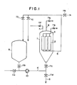
- FIGURE l which is an illustration of a flow sheet of a filtration system having a filtration apparatus according to the first embodiment of the invention
- the filtration apparatus l has a plural number of tubular filter elements 2 each having a circular or polygonal cross section in an upright disposition inside thereof.
- the upper ends of these filter elements 2 are connected to a gas exhaust tube 3 opening to the atmospheric air through a valve lle.
- the liquid to be filtered is introduced into the filtration apparatus l from the liquid feed line 4 through the valve llc by means of a pump l0.
- the pre-coat slurry contained in the pre-coat tank 9 is introduced into the filtration apparatus l through the valves llb and llc also by means of the pump l0.
- the filtrate coming out of the filter elements 2 is discharged through the filtrate discharge tube 5 while the liquid drain line 6 with a valve lld serves to empty the filtration apparatus l.
- the filtration apparatus l can be pressurized with a gas through the gas feed line 7 by opening the valve llf and the pressurizing gas can be released to the ambient atmosphere through the primary gas vent tube 8 by opening the valve llg.
- the system has several more valves lla, llh, lli, and llj.
- FIGURE 2 schematically illustrates an axial cross sectional view of another model of the filtration apparatus l and the reference numerals 2, 3 and 5 each correspond to the respective part 2, 3 or 5 in FIGURE l.
- Each of the filter elements 2 has an upper and a lower end member l2a and l2b by which it is held inside the housing of the filtration apparatus l provided with a pair of flanges l3 at which the covering can be disassempled from the body of the apparatus l.
- each of the filter elements 2 is composed of three unit members made of a ceramic material in a tandem arrangement by fastening with the upper and lower end members l2a and l2b.
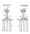
- FIGURES 3a and 3b are each a detailed illustration of a part of the apparatus shown in FIGURE 2 to demonstrate the conjunction of the gas exhaust tube 3 having a gas outlet opening 3a or 3b, respectively, to the filter element 2 by means of a spindle l4 for positioning of the filter element 2, a spring l5 and a nut l6.
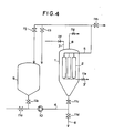
- FIGURE 4 which is an illustration of a flow sheet of a filtration system having a filtration apparatus according to the second embodiment of the invention
- the filtration apparatus l has a plural number of tubular filter elements 2 each having a circular or polygonal cross section in an upright disposition inside thereof.
- the lower ends of these filter elements 2 are connected to a liquid drain tube 3 ⁇ opening to the atmospheric air through a valve lle.
- the liquid to be filtered is introduced into the filtration apparatus l from the liquid feed line 4 through the valve llc by means of a pump l0.
- the pre-coat slurry contained in the pre-coat tank 9 is introduced into the filtration apparatus l through the valves llb and llc also by means of the pump l0.
- the filtrate coming out of the filter elements 2 is discharged through the filtrate discharge tube 5 while the liquid drain line 6 with a valve lld serves to empty the filtration apparatus l.
- the filtration apparatus l can be pressurized with a gas through the gas feed line 7 by opening the valve llf and the pressurizing gas can be released to the ambient atmosphere through the gas vent tube 8 ⁇ by opening the valve llg.
- the system has several more valves lla, llh, lli and llj.
- FIGURE 5 schematically illustrates an axial cross sectional view of another model of the filtration apparatus l according to the second embodiment of the invention.
- the reference numerals 2, 3 ⁇ and 5 each correspond to the respective part 2, 3 ⁇ or 5 in FIGURE 4.
- Each of the filter elements 2 has an upper and a lower end member l2a and l2b by which it is held inside the housing of the filtration apparatus l provided with a pair of flanges l3 at which the conical bottom member of the housing can be disassembled from the body of the apparatus l.
- Each of the filter elements 2 is a cylinder made of a ceramic material and held inside the housing of the apparatus l by means of the upper and lower end members l2a and l2b.
- FIGURE 6 is a detailed illustration of a part of the apparatus shown in FIGURE 5 to demonstrate the conjunction of the liquid drain tube 3 ⁇ having an opening 3 ⁇ a by means of a spindle l4 for positioning of the filter element 2 and a nut l6.
- FIGURE 7 is a detailed illustration of a part corresponding to FIGURE 6 of a filter element formed by spirally winding a wire around a tube of a puched metal tube or a corrugated rectangular tube showing the conjunction of the liquid drain tube 3 ⁇ with a liquid drain opening 3 ⁇ b and the filter element 2.
- Usable filter element in the inventive filtration apparatus includes a variety of known tubular ones having a circular or polygonal cross section without particular limitations.
- Particularly preferable filter elements are ceramic-made cylindrical elements, those formed by spirally winding a wire around a punched metal tube or a corrugated rectangular.
- Dimensions of the filter elements such as height, wall thickness, inner diameter and the like as well as the number of the filter elements uprightly installed in the filtration apparatus of the invention are not limitative and can be suitably selected to comply with the intended filtration process.
- each of the filter elements may be connected to a gas exhaust tube or liquid drain tube through a gas exhaust opening or liquid drain opening independently from the other filter elements.
- each of the filter elements is connected at the gas exhaust or liquid drain opening to one end of a separate gas exhaust tube or liquid drain tube while the other ends of the gas exhaust tubes or liquid drain tubes are combined in a single collecting pipe through which the gas or liquid is discharged.
- the inner diameter of the gas exhaust opening or liquid drain opening may be sufficient when an appropriate volume of the gas or liquid can be taken out of the filter element by pressurizing or filling the filtration apparatus with the gas or liquid.
- the gas exhaust opening should preferably have an inner diameter in the range from one fifteenth to one third of the inner diameter of the filter element while the liquid drain opening should preferably have an inner diameter which is not larger than the inner diameter of the filter element but not smaller than one twentieth of the inner diameter of the filter element.
- the inner diameter of the gas exhaust tube or liquid drain tube adequately selected in consideration of the cross sectional area of the gas exhaust opening or the liquid drain opening, the number of the filter elements in the filtration apparatus and other parameters.
- the gas exhaust tube or liquid drain tube should be made preferably of a stainless steel in most cases although the material may be selected depending on the particularly intended filtration process in which the inventive filtration apparatus is used.
- the most characteristic feature of the invention consists in the gas exhaust tube or liquid drain tube connected to the filter element at the upper part or lower part, respectively, thereof to give a possibility of filling the filtration apparatus with the liquid to be filtered or discharging the liquid for pre-coat forming keeping the once formed pre-coat layer in a defect-free condition. Namely, the procedures of forming of the pre-coat layer, discharging of the liquid for pre-coat forming, interruption of the liquid flow and filling of the filtration apparatus with the liquid to be filtered can be performed without the problem of falling of the pre-coat layer.
- the filtration process using the inventive filtration apparatus can be performed without the disadvantage due to the mixture of the liquid for pre-coat forming and the liquid to be filtered otherwise unavoidable in the transitive stage.
- formation of the pre-coat layer can be directly followed by complete discharge of the liquid used for the formation of the pre-coat layer out of the filtration apparatus prior to introduction of the liquid to be filtered into the apparatus without falling of the once formed pre-coat layer or formation of tiny holes therein.
- the filtration apparatus used in this test had l9 ceramic-made cylindrical filter elements uprightly installed in the housing.
- Each of the filter elements was constructed of three unit elements each having a height of 500 mm, inner diameter of 70 mm and wall thickness of 25 mm in a tandem arrangement.
- the spindle for positioning of the filter element was provided with a gas exhaust opening of 7 mm diameter at the upper end thereof so that the gas inside the apparatus could be discharged to the outer atmosphere through a gas exhaust tube connected to the opening.
- a filtration system was constructed using this filtration apparatus according to the flow sheet illustrated in FIGURE l.
- the pre-coat tank 9 was filled with an aqueous suspension of diatomaceous earth which was circulated along a path of valve llb, pump l0, valve llc, filtration apparatus l, filtrate discharge tube 5, valve llj and pre-coat tank 9 so as to form a pre-coat layer of diatomaceous earth on the outer surface of the filter elements 2.
- valves llb and llj were closed with the pump l0 turned off and, simultaneously, carbon dioxide gas was introduced into the filtration apparatus by opening the valve llf so as to discharge the water for pre-coat forming by opening the valve lli.
- the valve lld was opened to completely discharge the remaining water. Further, the water for pre-coat forming remaining in the piping between the valves lla and lld was discharged by opening the valves lla and lld for a short while followed by closing.
- the filtration apparatus l was filled with beer introduced therein to through the valve lla, pump l0 and valve llc.
- the air inside was discharged during this procedure through the secondary gas exhaust tube 3 by opening the valve lle.
- the beer was filtered through a path of the valve lla, pump l0, valve llc, filtration apparatus l and valve llh by simultaneously closing the valve lle and opening the valve llh.
- the filtration system and filtration apparatus were substantially the same as in Example l except that the apparatus had no secondary gas exhaust tube 3.
- the filtration apparatus was filled with beer under gas discharge by opening the valve llg or the valve lli. The results of filtration were not satisfactory due to partial falling of the pre-coat layer and formation of tiny holes in the upper part of the pre-coat layer.
- the filtration system was constructed according to the flow sheet illustrated in FIGURE l using a filtration apparatus in which a single ceramic-made cylindrical filter element was installed in an upright disposition.
- the filter element was constructed of three unit elements each having a height of 500 mm, inner diameter of 70 mm and wall thickness of 25 mm in a tandem arrangement and the upper end member l2a of the element was provided with a gas exhaust opening of 7 mm diameter to which a gas exhaust tube was connected.
- the procedure of filtration using the above described filtration system was substantially the same as in Example l excepting replacement of the beer with a sugar syrup and carbon dioxide gas with air. The results were that the sugar syrup could be filtered without dilution by intermixing of water and removal of the yeast contained in the sugar syrup was complete.
- the filtration system and filtration apparatus were substantially the same as in Example l except that the filtration apparatus had seven filter elements each formed of a corrugated rectangular tube having a height of 700 mm, inner diameter of 26 mm and wall thickness of 2 mm spirally wound with a wire.
- Oolong tea was filtered using this filtration apparatus in substantially the same manner as in Example l excepting replacement of the carbon dioxide gas with nitrogen. The results were that the Oolong tea could be filtered without dilution by intermixing of water and removal of the bacteria contained in the Oolong tea was complete.
- the filtration apparatus had seven ceramic-made cylindrical filter elements uprightly installed in the housing.
- Each of the filter elements had a height of 700 mm, inner diameter of 20 mm and wall thickness of 5 mm and the spindle for positioning of the filter element was provided with a liquid drain opening of 7 mm diameter at the lower end of the element so that the liquid inside the apparatus could be discharged to the outside of the apparatus through a liquid drain tube connected to the opening.
- a filtration system was constructed using this filtration apparatus according to the flow sheet illustrated in FIGURE 4.
- the pre-coat tank 9 was filled with an aqueous suspension of diatomaceous earth which was circulated along a path of valve llb, punp l0, valve llc, filtration apparatus l, filtrate discharge tube 5, valve llj and pre-coat tank 9 so as to form a pre-coat layer of diatomaceous earth on the outer surface of the filter elements 2.
- valves llb and llj were closed with the pump l0 turned off and, simultaneously, carbon dioxide gas was introduced into the filtration apparatus l by opening the valve llf so as to discharge the water for pre-coat forming by opening the valve lle.
- the valve lld was opened to completely discharge the remaining water. Further, the water for pre-coat forming remaining in the piping between the valves lla and lld was discharged by opening the valves lla and lld for a short while followed by closing.
- the filtration apparatus l was filled with beer introduced thereinto through the valve lla, pump l0 and valve llc.
- the air inside was discharged during this procedure by opening the valve lli.
- the beer was filtered through a path of the valve lla, pump l0, valve llc, filtration apparatus l and valve llh by simultaneously closing the valve lli and opening the valve llh.
- the system and apparatus for the filtration of beer were substantially the same as in Example 4 except that the filtration apparatus had no liquid drain tube 3 ⁇ and the water for pre-coat forming was discharged by opening the valves llc and lld and/or the valve lli.
- the results of filtration were not satisfactory due to partial falling of the pre-coat layer and formation of tiny holes in the pre-coat layer.
- the filtration system and filtration apparatus were substantially the same as in Example 4 except that the filtration apparatus had seven filter elements each formed of a corrugated rectangular tube having a height of 700 mm, inner diameter of 26 mm and wall thickness of 2 mm spirally wound with a wire.
- Oolong tea was filtered using this filtration apparatus in substantially the same manner as in Example 4 excepting replacement of the carbon dioxide gas with nitrogen. The results were that Oolong tea could be filtered without dilution by intermixing of water and removal of the bacteria contained in the Oolong tea was complete.
Landscapes
- Chemical & Material Sciences (AREA)
- Chemical Kinetics & Catalysis (AREA)
- Filtering Materials (AREA)
- Separation Using Semi-Permeable Membranes (AREA)
Abstract
Description
- The present invention relates to a filtration apparatus or, more particularly, to an improvement of a filtration apparatus in which a so-called pre-coat layer of a filter aid is formed on the surface of a filter element or filter medium and the liquid is filtered through the thus formed pre-coat layer. Filtration apparatuses of this type are widely used in the manufacturing process of alcoholic drinks such as beer, wine, Japanese sake and the like, seasonings such as soy sauce, vinegar, sugar, cooking oil and the like, other beverages such as fruit-based drinks, carbonated drinks, mineral water, Oolong tea and the like, pharmaceuticals and so on.
- As is known, a type of filtration procedures utilizes a pre-coat layer which is formed of a filter aid such as diatomaceous earth, perlite, cellulosic powder, active carbon and the like on the surface of filter elements in a substantial thickness and through which the liquid is filtered.
- The most conventional material as the filter element, on which the pre-coat layer is formed, includes filter cloth, filter net, filter paper and the like although several more rigid materials are sometimes used including punched metal tubes spirally wound with a wire, corrugated rectangular tubes (or tubes having an undulate polygonal cross section) spirally wound with a wire, ceramic-made cylindrical elements and so on. Different types of the filter elements may be used either alone or as a combination of two types or more.
- Various types of filtration apparatuses utilize one or more of cylindrical or polygonally tubular filter elements provided with a pre-coat layer in an upright disposition. These filtration apparatuses are classified into two classes depending on the position at which the filtrate is taken out of the filter element. Namely, the filtrate may be discharged at an upper part or at a lower part of the filter element. A problem in each of these filtration apparatuses is that, since the pre-coat layer is formed on a vertical surface at any rate, the pre-coat layer sometimes falls off the surface of the filter element not only in the course of the works for the formation of the pre-coat layer of a filter aid but also during the filtering works through the thus formed pre-coat layer, especially, when the liquid flow through the pre-coat layer is interrupted.
- In connection with the works for forming the pre-coat layer of a filter aid on the surface of a filter element, it is a possible way that the dispersion of the filter aid, from which the filter aid should be deposited to form the pre-coat layer on the surface of the filter element, is prepared by use of a liquid which is the liquid to be filtered therethrough. This method, in which the filter element and the filter aid are contacted from the very beginning by the liquid to be filtered, sometimes causes problems when the amount of certain soluble materials dissolved out from the filter aid and entering the filtrate must be limited or when microbiological contamination of the filtration system must be avoided. It is a usual practice in such cases that the pre-coat layer is formed using a dispersion of the filter aid in a liquid which is not the same one as the liquid to be filtered, such as cold or hot water, and thereafter the liquid passing through the pre-coat layer is gradually switched to the liquid to be filtered without interrupting the liquid flow therethrough.
- When a process of filtration is started with formation of a pre-coat layer in the above described manner, it is an unavoidable consequence that a considerably large portion of the liquid coming out of the filter element in the course of the above mentioned liquid switching is a mixture of the first liquid used as the dispersing medium of the filter aid to form the pre-coat layer and the second liquid which is the liquid to be subjected to the filtration treatment. Such a fraction of liquid mixture naturally contains the desired filtrate constituent only in a low concentration so that it is discarded as a waste or stored in a separate reservoir from which it is returned bit by bit to the preceding step of the process.
- The above mentioned way of discarding the transitive filtrate is undesirable when the filtered liquid is very expensive or when certain detriment is anticipated by discarding the liquid while the alternative way of collecting the transitive filtrate in a separate reservoir before disposal or recycling is economically disadvantageous in respect of the investment for the facilities and consumption of large manpower and time.
- In order to solve the above mentioned problem concerning the transitive filtrate which is a mixture of the liquid used for pre-coat forming and the liquid to be filtered, a method has been proposed in which the space inside the filter apparatus is pressurized with a gas such as air, carbon dioxide and the like after completion of formation of the pre-coat layer on the surface of the filter element so as to discharge the liquid used for pre-coat forming. This method also cannot provide a complete solution of the problem. For example, the pre-coat layer may fall off the surface of the filter element partly or wholly during the discharge of the liquid under pressurization or in the course of filling the filter element with the liquid to be filtered therethrough and tiny holes are sometimes formed in the pre-coat layer so that it is a difficult matter to keep the pre-coat layer in a complete defect-free condition. This problem is particularly serious in a filtration apparatus of the type in which the filtrate is taken out of the apparatus at an upper part thereof.
- Accordingly, the present invention has an object to provide a filtration apparatus in which the liquid is filtered through a pre-coat layer formed on the surface of a filter element without the problem by the transitive filtrate which is a mixture of the liquid used in the formation of the pre-coat layer and the liquid to be filtered.
- Thus, the apparatus of the present invention is, according to the first embodiment thereof, a filtration apparatus comprising a tubular filter element installed in an upright disposition having a surface on which a pre-coat layer of a filter aid is formed to filter a liquid therethrough, a gas exhaust tube being connected to the upright tubular filter element at the upper part thereof.
- Further, the apparatus of the present invention is, according to the second embodiment thereof, a filtration apparatus comprising a tubular filter element installed in an upright disposition having a surface on which a pre-coat layer of a filter aid is formed to filter a liquid therethrough, a liquid drain tube being connected to the upright tubular filter element at the lower part thereof.
-
- FIGURE l is an illustration of a flow sheet of a filtration system having a filtration apparatus according to the first embodiment of the invention built therein.
- FIGURE 2 schematically illustrates an axial cross sectional view of a filtration apparatus according to the first embodiment of the invention.
- FIGURES 3a and 3b are each a detailed illustration of a part of the filtration apparatus illustrated in FIGURE 2 showing the conjunction of the gas exhaust tube and the filter element.
- FIGURE 4 is an illustration of a flow sheet of a filtration system having a filtration apparatus according to the second embodiment of the invention built therein.
- FIGURE 5 schematically illustrates an axial cross sectional view of a filtration apparatus according to the second embodiment of the invention.
- FIGURE 6 is a detailed illustration of a part of the filtration apparatus illustrated in FIGURE 5 showing the conjunction of the liquid drain tube and the filter element.
- FIGURE 7 is a detailed illustration of a part corresponding to FIGURE 6 of a filter element formed by spirally winding a wire around a tube of a punched metal or a corrugated rectangular tube showing the conjunction of the liquid drain tube and the filter element.
- In the following, the filtration apparatus of the present invention is described in more detail with reference to the accompanying drawing.
- In FIGURE l which is an illustration of a flow sheet of a filtration system having a filtration apparatus according to the first embodiment of the invention, the filtration apparatus l has a plural number of
tubular filter elements 2 each having a circular or polygonal cross section in an upright disposition inside thereof. The upper ends of thesefilter elements 2 are connected to agas exhaust tube 3 opening to the atmospheric air through a valve lle. The liquid to be filtered is introduced into the filtration apparatus l from theliquid feed line 4 through the valve llc by means of a pump l0. The pre-coat slurry contained in thepre-coat tank 9 is introduced into the filtration apparatus l through the valves llb and llc also by means of the pump l0. The filtrate coming out of thefilter elements 2 is discharged through thefiltrate discharge tube 5 while theliquid drain line 6 with a valve lld serves to empty the filtration apparatus l. The filtration apparatus l can be pressurized with a gas through the gas feed line 7 by opening the valve llf and the pressurizing gas can be released to the ambient atmosphere through the primarygas vent tube 8 by opening the valve llg. The system has several more valves lla, llh, lli, and llj. - FIGURE 2 schematically illustrates an axial cross sectional view of another model of the filtration apparatus l and the
reference numerals respective part filter elements 2 has an upper and a lower end member l2a and l2b by which it is held inside the housing of the filtration apparatus l provided with a pair of flanges l3 at which the covering can be disassempled from the body of the apparatus l. In the apparatus illustrated in FIGURE 2, each of thefilter elements 2 is composed of three unit members made of a ceramic material in a tandem arrangement by fastening with the upper and lower end members l2a and l2b. FIGURES 3a and 3b are each a detailed illustration of a part of the apparatus shown in FIGURE 2 to demonstrate the conjunction of thegas exhaust tube 3 having a gas outlet opening 3a or 3b, respectively, to thefilter element 2 by means of a spindle l4 for positioning of thefilter element 2, a spring l5 and a nut l6. - In FIGURE 4 which is an illustration of a flow sheet of a filtration system having a filtration apparatus according to the second embodiment of the invention, the filtration apparatus l has a plural number of
tubular filter elements 2 each having a circular or polygonal cross section in an upright disposition inside thereof. The lower ends of thesefilter elements 2 are connected to a liquid drain tube 3ʹ opening to the atmospheric air through a valve lle. The liquid to be filtered is introduced into the filtration apparatus l from theliquid feed line 4 through the valve llc by means of a pump l0. The pre-coat slurry contained in thepre-coat tank 9 is introduced into the filtration apparatus l through the valves llb and llc also by means of the pump l0. The filtrate coming out of thefilter elements 2 is discharged through thefiltrate discharge tube 5 while theliquid drain line 6 with a valve lld serves to empty the filtration apparatus l. The filtration apparatus l can be pressurized with a gas through the gas feed line 7 by opening the valve llf and the pressurizing gas can be released to the ambient atmosphere through the gas vent tube 8ʹ by opening the valve llg. The system has several more valves lla, llh, lli and llj. - FIGURE 5 schematically illustrates an axial cross sectional view of another model of the filtration apparatus l according to the second embodiment of the invention. The
reference numerals 2, 3ʹ and 5 each correspond to therespective part 2, 3ʹ or 5 in FIGURE 4. Each of thefilter elements 2 has an upper and a lower end member l2a and l2b by which it is held inside the housing of the filtration apparatus l provided with a pair of flanges l3 at which the conical bottom member of the housing can be disassembled from the body of the apparatus l. Each of thefilter elements 2 is a cylinder made of a ceramic material and held inside the housing of the apparatus l by means of the upper and lower end members l2a and l2b. FIGURE 6 is a detailed illustration of a part of the apparatus shown in FIGURE 5 to demonstrate the conjunction of the liquid drain tube 3ʹ having an opening 3ʹa by means of a spindle l4 for positioning of thefilter element 2 and a nut l6. FIGURE 7 is a detailed illustration of a part corresponding to FIGURE 6 of a filter element formed by spirally winding a wire around a tube of a puched metal tube or a corrugated rectangular tube showing the conjunction of the liquid drain tube 3ʹ with a liquid drain opening 3ʹb and thefilter element 2. - Usable filter element in the inventive filtration apparatus includes a variety of known tubular ones having a circular or polygonal cross section without particular limitations. Particularly preferable filter elements are ceramic-made cylindrical elements, those formed by spirally winding a wire around a punched metal tube or a corrugated rectangular. Dimensions of the filter elements such as height, wall thickness, inner diameter and the like as well as the number of the filter elements uprightly installed in the filtration apparatus of the invention are not limitative and can be suitably selected to comply with the intended filtration process. When the filtration apparatus has a plurality of the filter elements, each of the filter elements may be connected to a gas exhaust tube or liquid drain tube through a gas exhaust opening or liquid drain opening independently from the other filter elements. Alternatively, it is preferable that each of the filter elements is connected at the gas exhaust or liquid drain opening to one end of a separate gas exhaust tube or liquid drain tube while the other ends of the gas exhaust tubes or liquid drain tubes are combined in a single collecting pipe through which the gas or liquid is discharged.
- The inner diameter of the gas exhaust opening or liquid drain opening may be sufficient when an appropriate volume of the gas or liquid can be taken out of the filter element by pressurizing or filling the filtration apparatus with the gas or liquid. According to the results of the experiments undertaken by the inventors, the gas exhaust opening should preferably have an inner diameter in the range from one fifteenth to one third of the inner diameter of the filter element while the liquid drain opening should preferably have an inner diameter which is not larger than the inner diameter of the filter element but not smaller than one twentieth of the inner diameter of the filter element. When the inner diameter of the gas exhaust opening or the liquid drain opening is outside the above mentioned respective range, the gas exhaustion or liquid drain cannot be achieved with an efficiency as high as desired. The inner diameter of the gas exhaust tube or liquid drain tube adequately selected in consideration of the cross sectional area of the gas exhaust opening or the liquid drain opening, the number of the filter elements in the filtration apparatus and other parameters. The gas exhaust tube or liquid drain tube should be made preferably of a stainless steel in most cases although the material may be selected depending on the particularly intended filtration process in which the inventive filtration apparatus is used.
- As is described above in detail, the most characteristic feature of the invention consists in the gas exhaust tube or liquid drain tube connected to the filter element at the upper part or lower part, respectively, thereof to give a possibility of filling the filtration apparatus with the liquid to be filtered or discharging the liquid for pre-coat forming keeping the once formed pre-coat layer in a defect-free condition. Namely, the procedures of forming of the pre-coat layer, discharging of the liquid for pre-coat forming, interruption of the liquid flow and filling of the filtration apparatus with the liquid to be filtered can be performed without the problem of falling of the pre-coat layer. Thus, the filtration process using the inventive filtration apparatus can be performed without the disadvantage due to the mixture of the liquid for pre-coat forming and the liquid to be filtered otherwise unavoidable in the transitive stage. This is because, in the inventive filtration apparatus, different from conventional filtration apparatuses utilizing a pre-coat layer, formation of the pre-coat layer can be directly followed by complete discharge of the liquid used for the formation of the pre-coat layer out of the filtration apparatus prior to introduction of the liquid to be filtered into the apparatus without falling of the once formed pre-coat layer or formation of tiny holes therein. Absence of the liquid mixture otherwise produced in the transitive stage of switching from the liquid for pre-coat forming to the liquid to be filtered provides great advantages not only relative to the costs for the disposal or recycling treatment of such a liquid mixture but also in respect of improvements in the quality of the product produced in the process involving filtration.
- In the following, the filtration apparatus of the invention is described in more datail by way of examples.
- The filtration apparatus used in this test had l9 ceramic-made cylindrical filter elements uprightly installed in the housing. Each of the filter elements was constructed of three unit elements each having a height of 500 mm, inner diameter of 70 mm and wall thickness of 25 mm in a tandem arrangement. The spindle for positioning of the filter element was provided with a gas exhaust opening of 7 mm diameter at the upper end thereof so that the gas inside the apparatus could be discharged to the outer atmosphere through a gas exhaust tube connected to the opening. A filtration system was constructed using this filtration apparatus according to the flow sheet illustrated in FIGURE l.
- The
pre-coat tank 9 was filled with an aqueous suspension of diatomaceous earth which was circulated along a path of valve llb, pump l0, valve llc, filtration apparatus l,filtrate discharge tube 5, valve llj andpre-coat tank 9 so as to form a pre-coat layer of diatomaceous earth on the outer surface of thefilter elements 2. - When the pre-coat layer had been completed, the valves llb and llj were closed with the pump l0 turned off and, simultaneously, carbon dioxide gas was introduced into the filtration apparatus by opening the valve llf so as to discharge the water for pre-coat forming by opening the valve lli. When the liquid surface in the filtration apparatus l had reached the level of the
filtrate discharge tube 5, the valve lld was opened to completely discharge the remaining water. Further, the water for pre-coat forming remaining in the piping between the valves lla and lld was discharged by opening the valves lla and lld for a short while followed by closing. - Thereafter, the filtration apparatus l was filled with beer introduced therein to through the valve lla, pump l0 and valve llc. The air inside was discharged during this procedure through the secondary
gas exhaust tube 3 by opening the valve lle. After completion of filling of the apparatus with the beer, the beer was filtered through a path of the valve lla, pump l0, valve llc, filtration apparatus l and valve llh by simultaneously closing the valve lle and opening the valve llh. - The above described filtration of beer could be performed absolutely without producing a mixture of the water for pre-coat forming and the beer and removal of the yeast contained in the beer was complete. No defects were found at all in the pre-coat layer during the filtration procedure such as falling of the layer and formation of tiny holes therein.
- The filtration system and filtration apparatus were substantially the same as in Example l except that the apparatus had no secondary
gas exhaust tube 3. The filtration apparatus was filled with beer under gas discharge by opening the valve llg or the valve lli. The results of filtration were not satisfactory due to partial falling of the pre-coat layer and formation of tiny holes in the upper part of the pre-coat layer. - The filtration system was constructed according to the flow sheet illustrated in FIGURE l using a filtration apparatus in which a single ceramic-made cylindrical filter element was installed in an upright disposition. The filter element was constructed of three unit elements each having a height of 500 mm, inner diameter of 70 mm and wall thickness of 25 mm in a tandem arrangement and the upper end member l2a of the element was provided with a gas exhaust opening of 7 mm diameter to which a gas exhaust tube was connected.
- The procedure of filtration using the above described filtration system was substantially the same as in Example l excepting replacement of the beer with a sugar syrup and carbon dioxide gas with air. The results were that the sugar syrup could be filtered without dilution by intermixing of water and removal of the yeast contained in the sugar syrup was complete.
- The filtration system and filtration apparatus were substantially the same as in Example l except that the filtration apparatus had seven filter elements each formed of a corrugated rectangular tube having a height of 700 mm, inner diameter of 26 mm and wall thickness of 2 mm spirally wound with a wire. Oolong tea was filtered using this filtration apparatus in substantially the same manner as in Example l excepting replacement of the carbon dioxide gas with nitrogen. The results were that the Oolong tea could be filtered without dilution by intermixing of water and removal of the bacteria contained in the Oolong tea was complete.
- The filtration apparatus had seven ceramic-made cylindrical filter elements uprightly installed in the housing. Each of the filter elements had a height of 700 mm, inner diameter of 20 mm and wall thickness of 5 mm and the spindle for positioning of the filter element was provided with a liquid drain opening of 7 mm diameter at the lower end of the element so that the liquid inside the apparatus could be discharged to the outside of the apparatus through a liquid drain tube connected to the opening. A filtration system was constructed using this filtration apparatus according to the flow sheet illustrated in FIGURE 4.
- The
pre-coat tank 9 was filled with an aqueous suspension of diatomaceous earth which was circulated along a path of valve llb, punp l0, valve llc, filtration apparatus l,filtrate discharge tube 5, valve llj andpre-coat tank 9 so as to form a pre-coat layer of diatomaceous earth on the outer surface of thefilter elements 2. - When the pre-coat layer had been completed, the valves llb and llj were closed with the pump l0 turned off and, simultaneously, carbon dioxide gas was introduced into the filtration apparatus l by opening the valve llf so as to discharge the water for pre-coat forming by opening the valve lle. When the liquid surface in the filtration apparatus l had reached the level of the liquid drain tube 3ʹ, the valve lld was opened to completely discharge the remaining water. Further, the water for pre-coat forming remaining in the piping between the valves lla and lld was discharged by opening the valves lla and lld for a short while followed by closing.
- Thereafter, the filtration apparatus l was filled with beer introduced thereinto through the valve lla, pump l0 and valve llc. The air inside was discharged during this procedure by opening the valve lli. After completion of filling of the apparatus with the beer, the beer was filtered through a path of the valve lla, pump l0, valve llc, filtration apparatus l and valve llh by simultaneously closing the valve lli and opening the valve llh.
- The above described filtration of beer could be performed absolutely without producing a mixture of the water for pre-coat forming and the beer and removal of the yeast contained in the beer was complete. No defects were found at all in the pre-coat layer during the filtration procedure such as falling of the layer and formation of tiny holes therein.
- The system and apparatus for the filtration of beer were substantially the same as in Example 4 except that the filtration apparatus had no liquid drain tube 3ʹ and the water for pre-coat forming was discharged by opening the valves llc and lld and/or the valve lli. The results of filtration were not satisfactory due to partial falling of the pre-coat layer and formation of tiny holes in the pre-coat layer.
- The filtration system and filtration apparatus were substantially the same as in Example 4 except that the filtration apparatus had seven filter elements each formed of a corrugated rectangular tube having a height of 700 mm, inner diameter of 26 mm and wall thickness of 2 mm spirally wound with a wire. Oolong tea was filtered using this filtration apparatus in substantially the same manner as in Example 4 excepting replacement of the carbon dioxide gas with nitrogen. The results were that Oolong tea could be filtered without dilution by intermixing of water and removal of the bacteria contained in the Oolong tea was complete.
Claims (2)
Applications Claiming Priority (4)
| Application Number | Priority Date | Filing Date | Title |
|---|---|---|---|
| JP61056026A JPS61246677A (en) | 1985-03-13 | 1986-03-12 | Phase-difference trouble detector |
| JP61068850A JPS61229885A (en) | 1985-03-28 | 1986-03-28 | Manufacture of aminopropylalkoxysilane |
| JP56026/86 | 1986-04-16 | ||
| JP68850/86 | 1986-05-09 |
Publications (3)
| Publication Number | Publication Date |
|---|---|
| EP0245585A2 true EP0245585A2 (en) | 1987-11-19 |
| EP0245585A3 EP0245585A3 (en) | 1988-07-13 |
| EP0245585B1 EP0245585B1 (en) | 1990-06-27 |
Family
ID=26396938
Family Applications (1)
| Application Number | Title | Priority Date | Filing Date |
|---|---|---|---|
| EP87101791A Expired - Lifetime EP0245585B1 (en) | 1986-03-12 | 1987-02-10 | A filtration apparatus |
Country Status (2)
| Country | Link |
|---|---|
| US (1) | US4786408A (en) |
| EP (1) | EP0245585B1 (en) |
Cited By (9)
| Publication number | Priority date | Publication date | Assignee | Title |
|---|---|---|---|---|
| WO2006099915A1 (en) * | 2005-03-24 | 2006-09-28 | Hydac Process Technology Gmbh | Filter installation and method for operating one such filter installation |
| DE102009016490A1 (en) * | 2009-04-06 | 2010-10-14 | Krones Ag | Production of soy sauce by means of precoat candle filter |
| US9352252B2 (en) | 2011-04-27 | 2016-05-31 | Lifestraw Sa | Water purification device |
| EP2891512A4 (en) * | 2012-08-28 | 2016-06-15 | Kanagawa Kiki Kogyo Co Ltd | FILTER ELEMENT STRUCTURE AND CURVED WASH FILTRATION DEVICE WITH FILTER ELEMENT STRUCTURE |
| CN105903260A (en) * | 2015-02-20 | 2016-08-31 | 欧洲技术设于伊特根的三聚氰氨-卢森堡-分支机构 | Filtering and decoloration module and method of melamine solution in melamine production device, and melamine production device by using the same |
| USD782610S1 (en) | 2015-11-09 | 2017-03-28 | Lifestraw Sa | Water purifier |
| USD782609S1 (en) | 2015-07-14 | 2017-03-28 | Lifestraw Sa | Water purifier |
| USD783773S1 (en) | 2015-07-14 | 2017-04-11 | Lifestraw Sa | Water purifier |
| US11053141B2 (en) | 2013-10-28 | 2021-07-06 | Vestergaard Sa | Water purification device |
Families Citing this family (6)
| Publication number | Priority date | Publication date | Assignee | Title |
|---|---|---|---|---|
| JPH0357595A (en) * | 1989-07-24 | 1991-03-12 | Kuri Kagaku Sochi Kk | Continuous filtering device |
| US5152815A (en) * | 1989-09-05 | 1992-10-06 | Zievers James F | Type 114 tiered filter |
| US5441633A (en) * | 1992-09-25 | 1995-08-15 | Schewitz; Jonathan | Liquid filter using filtration aid |
| DE102010055522B3 (en) * | 2010-12-22 | 2012-06-06 | Khs Gmbh | Apparatus and method for filtration of fluids |
| FI20116000A7 (en) * | 2011-10-11 | 2013-04-12 | Outotec Filters Oy | Method and apparatus for forming a pre-coating on the surface of the filtration media of a clarification filter |
| US9421498B2 (en) * | 2012-11-12 | 2016-08-23 | Pall Corporation | Systems and methods for conditioning a filter assembly |
Family Cites Families (7)
| Publication number | Priority date | Publication date | Assignee | Title |
|---|---|---|---|---|
| DE583320C (en) * | 1924-02-18 | 1933-09-01 | Jules Cuenoud | Precoat filters for liquids and processes for the production of precoat filter sheets |
| US3666097A (en) * | 1970-06-08 | 1972-05-30 | Ecodyne Corp | Method and apparatus for cleaning a filter cartridge |
| US3997441A (en) * | 1975-04-21 | 1976-12-14 | Pamplin Jr Lee F | Pressure filter separator |
| US4267039A (en) * | 1977-12-05 | 1981-05-12 | Ecodyne Corporation | Fluid filtration method and apparatus |
| US4293414A (en) * | 1978-05-04 | 1981-10-06 | Ecodyne Corporation | Slotted sheet filter element |
| US4547296A (en) * | 1983-09-15 | 1985-10-15 | Croll-Reynolds Engineering Co., Inc. | Heel recovery filtration process and apparatus |
| EP0153972B1 (en) * | 1984-03-08 | 1987-05-27 | Heinz Schumacher | Method and apparatus for cleaning filter elements, especially for filter candles |
-
1987
- 1987-02-10 EP EP87101791A patent/EP0245585B1/en not_active Expired - Lifetime
- 1987-02-11 US US07/013,447 patent/US4786408A/en not_active Expired - Fee Related
Cited By (13)
| Publication number | Priority date | Publication date | Assignee | Title |
|---|---|---|---|---|
| WO2006099915A1 (en) * | 2005-03-24 | 2006-09-28 | Hydac Process Technology Gmbh | Filter installation and method for operating one such filter installation |
| JP2008534244A (en) * | 2005-03-24 | 2008-08-28 | ハイダック プロセス テクノロジー ゲゼルシャフト ミット ベシュレンクテル ハフツング | Filter equipment and method of operating filter equipment |
| US7691274B2 (en) | 2005-03-24 | 2010-04-06 | Hydac Process Technology Gmbh | Filter installation and method for operating one such filter installation |
| JP4856167B2 (en) * | 2005-03-24 | 2012-01-18 | ハイダック プロセス テクノロジー ゲゼルシャフト ミット ベシュレンクテル ハフツング | Filter equipment and method of operating filter equipment |
| DE102009016490A1 (en) * | 2009-04-06 | 2010-10-14 | Krones Ag | Production of soy sauce by means of precoat candle filter |
| US9352252B2 (en) | 2011-04-27 | 2016-05-31 | Lifestraw Sa | Water purification device |
| EP2891512A4 (en) * | 2012-08-28 | 2016-06-15 | Kanagawa Kiki Kogyo Co Ltd | FILTER ELEMENT STRUCTURE AND CURVED WASH FILTRATION DEVICE WITH FILTER ELEMENT STRUCTURE |
| US11053141B2 (en) | 2013-10-28 | 2021-07-06 | Vestergaard Sa | Water purification device |
| US12012341B2 (en) | 2013-10-28 | 2024-06-18 | Lifestraw Sarl | Water purification device |
| CN105903260A (en) * | 2015-02-20 | 2016-08-31 | 欧洲技术设于伊特根的三聚氰氨-卢森堡-分支机构 | Filtering and decoloration module and method of melamine solution in melamine production device, and melamine production device by using the same |
| USD782609S1 (en) | 2015-07-14 | 2017-03-28 | Lifestraw Sa | Water purifier |
| USD783773S1 (en) | 2015-07-14 | 2017-04-11 | Lifestraw Sa | Water purifier |
| USD782610S1 (en) | 2015-11-09 | 2017-03-28 | Lifestraw Sa | Water purifier |
Also Published As
| Publication number | Publication date |
|---|---|
| EP0245585B1 (en) | 1990-06-27 |
| US4786408A (en) | 1988-11-22 |
| EP0245585A3 (en) | 1988-07-13 |
Similar Documents
| Publication | Publication Date | Title |
|---|---|---|
| EP0245585A2 (en) | A filtration apparatus | |
| EP0634362B1 (en) | Liquid purification system | |
| US5906151A (en) | Apparatus and method for brewing an alcoholic beverage and beverage brewed by same | |
| US4728423A (en) | Plural cylindrical filter units with displacement support | |
| US4411785A (en) | Reverse osmosis hollow fiber filter element | |
| HU220699B1 (en) | Fermenter | |
| KR20090089454A (en) | Use of the First Liquid Filtration / Stabilization Facility for Triple Purposes | |
| US20110177219A1 (en) | Method, System and Apparatus for Removing Impurities From Wine | |
| US20130193089A1 (en) | System and method for filtering beverages | |
| CA1324089C (en) | Filtration apparatus | |
| EP0177315A2 (en) | Automatic backwashing filter | |
| US20040065627A1 (en) | Precoat filter cartridge, precoat cartridge filter and use of a filter cartridge | |
| JPS58163412A (en) | Filter | |
| US20150367267A1 (en) | Filtering methods for fluids and devices for carrying out said methods | |
| WO1996023570A1 (en) | Multi-function fluid treatment system and method for using the same | |
| US6102212A (en) | Filter element | |
| JPH0328888Y2 (en) | ||
| US20100068360A1 (en) | Method of operating a container filling plant for filling containers with filtered liquid, such as beer | |
| CN214232997U (en) | Multistage filtration equipment is used in beer preparation | |
| JP3979732B2 (en) | Sake filtration method and filtration element for achieving the same | |
| JPS62250922A (en) | Liquid filtering method | |
| US4923609A (en) | Method and apparatus for purifying liquids employing a particulate filter and a membrane | |
| CN210964153U (en) | Micron filter device | |
| EP4653072A1 (en) | Filter assembly for a fermentation vessel and a fermentation vessel comprising the filter assembly | |
| DE102019003724A1 (en) | Method and device for flavoring beverages |
Legal Events
| Date | Code | Title | Description |
|---|---|---|---|
| PUAI | Public reference made under article 153(3) epc to a published international application that has entered the european phase |
Free format text: ORIGINAL CODE: 0009012 |
|
| AK | Designated contracting states |
Kind code of ref document: A2 Designated state(s): CH DE FR GB IT LI NL |
|
| PUAL | Search report despatched |
Free format text: ORIGINAL CODE: 0009013 |
|
| AK | Designated contracting states |
Kind code of ref document: A3 Designated state(s): CH DE FR GB IT LI NL |
|
| 17P | Request for examination filed |
Effective date: 19890105 |
|
| 17Q | First examination report despatched |
Effective date: 19890522 |
|
| GRAA | (expected) grant |
Free format text: ORIGINAL CODE: 0009210 |
|
| AK | Designated contracting states |
Kind code of ref document: B1 Designated state(s): CH DE FR GB IT LI NL |
|
| REF | Corresponds to: |
Ref document number: 3763365 Country of ref document: DE Date of ref document: 19900802 |
|
| ET | Fr: translation filed | ||
| ITF | It: translation for a ep patent filed | ||
| PLBE | No opposition filed within time limit |
Free format text: ORIGINAL CODE: 0009261 |
|
| STAA | Information on the status of an ep patent application or granted ep patent |
Free format text: STATUS: NO OPPOSITION FILED WITHIN TIME LIMIT |
|
| 26N | No opposition filed | ||
| PGFP | Annual fee paid to national office [announced via postgrant information from national office to epo] |
Ref country code: CH Payment date: 19940119 Year of fee payment: 8 |
|
| PGFP | Annual fee paid to national office [announced via postgrant information from national office to epo] |
Ref country code: FR Payment date: 19940126 Year of fee payment: 8 |
|
| PGFP | Annual fee paid to national office [announced via postgrant information from national office to epo] |
Ref country code: GB Payment date: 19940131 Year of fee payment: 8 |
|
| ITTA | It: last paid annual fee | ||
| PGFP | Annual fee paid to national office [announced via postgrant information from national office to epo] |
Ref country code: NL Payment date: 19940228 Year of fee payment: 8 |
|
| PGFP | Annual fee paid to national office [announced via postgrant information from national office to epo] |
Ref country code: DE Payment date: 19940306 Year of fee payment: 8 |
|
| PG25 | Lapsed in a contracting state [announced via postgrant information from national office to epo] |
Ref country code: GB Effective date: 19950210 |
|
| PG25 | Lapsed in a contracting state [announced via postgrant information from national office to epo] |
Ref country code: LI Effective date: 19950228 Ref country code: CH Effective date: 19950228 |
|
| PG25 | Lapsed in a contracting state [announced via postgrant information from national office to epo] |
Ref country code: NL Effective date: 19950901 |
|
| GBPC | Gb: european patent ceased through non-payment of renewal fee |
Effective date: 19950210 |
|
| PG25 | Lapsed in a contracting state [announced via postgrant information from national office to epo] |
Ref country code: FR Effective date: 19951031 |
|
| NLV4 | Nl: lapsed or anulled due to non-payment of the annual fee |
Effective date: 19950901 |
|
| PG25 | Lapsed in a contracting state [announced via postgrant information from national office to epo] |
Ref country code: DE Effective date: 19951101 |
|
| REG | Reference to a national code |
Ref country code: FR Ref legal event code: ST |
|
| PG25 | Lapsed in a contracting state [announced via postgrant information from national office to epo] |
Ref country code: IT Free format text: LAPSE BECAUSE OF NON-PAYMENT OF DUE FEES;WARNING: LAPSES OF ITALIAN PATENTS WITH EFFECTIVE DATE BEFORE 2007 MAY HAVE OCCURRED AT ANY TIME BEFORE 2007. THE CORRECT EFFECTIVE DATE MAY BE DIFFERENT FROM THE ONE RECORDED. Effective date: 20050210 |