EP0245572A2 - Felsenbrechanlage - Google Patents
Felsenbrechanlage Download PDFInfo
- Publication number
- EP0245572A2 EP0245572A2 EP86630087A EP86630087A EP0245572A2 EP 0245572 A2 EP0245572 A2 EP 0245572A2 EP 86630087 A EP86630087 A EP 86630087A EP 86630087 A EP86630087 A EP 86630087A EP 0245572 A2 EP0245572 A2 EP 0245572A2
- Authority
- EP
- European Patent Office
- Prior art keywords
- weight
- tool
- column
- guide column
- strike
- Prior art date
- Legal status (The legal status is an assumption and is not a legal conclusion. Google has not performed a legal analysis and makes no representation as to the accuracy of the status listed.)
- Granted
Links
- 239000011435 rock Substances 0.000 title claims abstract description 17
- 230000005484 gravity Effects 0.000 claims abstract description 12
- 230000000694 effects Effects 0.000 claims abstract description 7
- 239000011359 shock absorbing material Substances 0.000 claims abstract description 4
- 239000000463 material Substances 0.000 claims description 5
- 239000012530 fluid Substances 0.000 description 8
- 230000004913 activation Effects 0.000 description 5
- 238000010586 diagram Methods 0.000 description 5
- 229910000760 Hardened steel Inorganic materials 0.000 description 2
- 230000006870 function Effects 0.000 description 2
- 241001379910 Ephemera danica Species 0.000 description 1
- 239000013536 elastomeric material Substances 0.000 description 1
- 238000012423 maintenance Methods 0.000 description 1
- 239000002184 metal Substances 0.000 description 1
- 230000004048 modification Effects 0.000 description 1
- 238000012986 modification Methods 0.000 description 1
- 229920003023 plastic Polymers 0.000 description 1
- 239000004033 plastic Substances 0.000 description 1
- 229920002635 polyurethane Polymers 0.000 description 1
- 239000004814 polyurethane Substances 0.000 description 1
- 230000009467 reduction Effects 0.000 description 1
- 230000035939 shock Effects 0.000 description 1
- 230000000007 visual effect Effects 0.000 description 1
Images


Classifications
-
- B—PERFORMING OPERATIONS; TRANSPORTING
- B25—HAND TOOLS; PORTABLE POWER-DRIVEN TOOLS; MANIPULATORS
- B25D—PERCUSSIVE TOOLS
- B25D11/00—Portable percussive tools with electromotor or other motor drive
- B25D11/06—Means for driving the impulse member
-
- B—PERFORMING OPERATIONS; TRANSPORTING
- B25—HAND TOOLS; PORTABLE POWER-DRIVEN TOOLS; MANIPULATORS
- B25D—PERCUSSIVE TOOLS
- B25D17/00—Details of, or accessories for, portable power-driven percussive tools
- B25D17/24—Damping the reaction force
-
- B—PERFORMING OPERATIONS; TRANSPORTING
- B28—WORKING CEMENT, CLAY, OR STONE
- B28D—WORKING STONE OR STONE-LIKE MATERIALS
- B28D1/00—Working stone or stone-like materials, e.g. brick, concrete or glass, not provided for elsewhere; Machines, devices, tools therefor
- B28D1/26—Working stone or stone-like materials, e.g. brick, concrete or glass, not provided for elsewhere; Machines, devices, tools therefor by impact tools, e.g. by chisels or other tools having a cutting edge
Definitions
- This invention relates to improvements in rock-breaking apparatus of the general type described in Australian patent specification no. AU-B-27994/77 (522890).
- Rock breaking apparatus of that type includes a rock-breaking tool, a tool housing having a bore therethrough, in which the tool body is mounted for limited movement axial to the bore, a weight designed to fall under the influence of gravity to impart an impulse to said tool, and means to raise the weight.
- the invention provides apparatus for breaking rocks or the like, in which a guide column (112) within which a weight (12) falls under gravity to strike a tool (134) or other article, characterized in that shock-absorbing material (146) is located at or near the base of said column such that it enables force to be transmitted from said weight (12) to a tool (134), whilst minimising the effect of the impact of said weight (12) on other parts of said apparatus.
- the invention also provides apparatus for breaking rocks, in which a weight (12) is allowed to fall, under the influence of gravity, in a guide column (112), to strike a tool (134) or other article, said tool (134) being mounted for limited movement in an aperture (132) in the base of said column, characterized in that said tool has a recessed portion (140) which co-operates with a retaining pin (144) located substantially at right angles to the axis of said aperture.
- the invention further provides apparatus for breaking rocks, in which a weight (12) may fall under the influence of gravity to strike a tool (134) or other article, characterized by operating means for operating said apparatus, including means for raising a weight, means for holding a weight in one of a number of positions and means for allowing said weight to fall.
- the invention also provides apparatus for breaking rock ⁇ s in which a weight (12) may fall under the influence of gravity in a guide column (112) to strike a tool (134), characterized by tool and/or weight sensing means (26) located on or near said column (112).
- the rock-breaking apparatus is of the general type illustrated in Figure 1 of Australian patent specification no. AU-B-27994/77 (522890).
- the apparatus 10 of Figure 1 includes a lower end 110, an embodiment of which will be described in detail hereinafter, a guide column 112, a weight 12 located for movement within said column, and a cable 14 or the like connecting weight 12 with a drum 16 around a pulley 18.
- the apparatus also includes hydraulic components such as a valve bank system, to be described in detail hereinafter, a high torque motor 20, an hydraulic clutch 22 (which may be a centrifugal clutch, but this is not preferred) and a high torque gearbox 24 incorporated into drum 16.
- hydraulic components such as a valve bank system, to be described in detail hereinafter, a high torque motor 20, an hydraulic clutch 22 (which may be a centrifugal clutch, but this is not preferred) and a high torque gearbox 24 incorporated into drum 16.
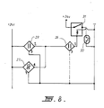
- Proximity switches 26, 27 and 29 are located on guide column 112 to detect positions of weight 12 and pin 144 (described hereinafter). The operation of the switches will be described in relation to Fig. 8.
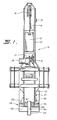
- the housing 110 of this embodiment is located at the lower end of guide column 112, which is shown (Fig. 2) having a generally square cross-section.
- the weight (not shown in this figure) has a corresponding square cross-section, although of course one with a circular cross-section could also be used.
- annular plate 114 Welded to the lower end of column 112 is an annular plate 114, which is also connected to the column 112 by rib plates 116.
- Lower plate 118 is secured to annular plate 114 by bolts 120, each of which passes through an aperture in plate 114, and is screwed into a corresponding threaded aperture in the hardened steel of plate 118.
- a hardened wear washer 128 is provided adjacent plate 114.
- a resilient gasket or the like 130 may be provided between plates 114 and 118, to act as a cut-off point for shock waves being transmitted from one metal surface to another. The gasket 130 may alternatively be omitted.
- Plate 118 has an axial cylindrical bore 132 therethrough, co-axial with guide column 112.
- a generally cylindrical hardened steel tool 134 is mounted, for axial movement, in bore 132.
- the tool 134 has curved edges 136 at its working end 138, such that the tool is quite blunt.
- Tool 134 also has a recess 140 in one side thereof.
- An off-centre transverse bore 142 is also provided in plate 118. It is designed to accommodate a pin 144, which in use co-operates with recess 140 to limit the axial movement of tool 134 in bore 132.
- the pin 144 is designed, as stated, to limit the axial movement of tool 134 in bore 132, but also serves to enable the tool 132 to be removed therefrom, without having a split-plate arrangement such as that of the prior art.
- Many alternative forms of location and securement of pin 144 in the aperture 142 may be utilised; the pin may be slightly tapered to allow it to be hammered into place, but to also allow it to be easily removed upon the application of a reverse impulse.
- a circlip may be used to secure this pin also.
- annulus 146 Located within guide column 112 is an annulus 146 of polyurethane, or any other suitable material, such as a relatively dense plastics or elastomeric material capable of deformation, but with a 'memory' which allows it to return to its original shape after deformation.
- the lower end 110 operates as follows.
- the weight (not shown) would then be allowed to fall under the influence of gravity, to strike the top of the tool 134, to propel it downwards to break the rock. It can be seen that the top of tool 134 protrudes above annulus 146, so that initially the force of the weight is taken fully by the tool 134. When the weight reaches the top of annulus 146, the annulus also absorbs some of the force, and serves as a cushioning member, allowing itself to be deformed such that (as viewed in Fig. 2) the material of the annulus can move into the corners 148 of the guide column 112, which corners are normally unoccupied by material.
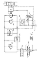
- Fig. 4 is a circuit diagram of an hydraulic system which may be used to operate the apparatus of Fig. 1.
- the following components shown in Fig. 1 also appear in Fig. 4; hydraulic motor 20, hydraulic clutch 24 and drum 16.
- Gearbox 24 (mentioned in relation to Fig. 1) is also shown.
- the system includes relief or check valves 200,202 which act to protect major components.
- Flow-control valve 204 permits a flow of approximately 220 litres per minute of fluid during the 'raise' mode (to be described hereinafter) and acts to divert excess flow back to the carrier/hydraulic pump 212.
- a two-way solenoid valve 206 allows all the flow (fluid) to pass back to the carrier when signalled to do so by proximity switch 26 (Fig. 1). This prevents the tool 134 (Figs. 2 and 3) striking the inside top of guide column 112 (Fig. 1) in the absence of an operator releasing the apparatus from the 'raise' mode.
- a pressure-reducing valve 208 allows the required pressure to pass, allowing the activation valve 210 to activate.
- the activation valve 210 activates hydraulic clutch 22 with a pressure of approximately 420 p.s.i. (30 BAR) to allow clutch 22 to engage.
- Valve 210 also allows the clutch 22 to disengage when the 'release' mode is selected by an operator or the like.
- valves 200 to 210 inclusive are incorporated in a valve bank; that is, the valves are located in proximity to one another in a single housing, and the hydraulic conduits are plumbed to the valves in the valve bank. Such an arrangement is more efficient for maintenance.
- the valves may be located in other appropriate ways.
- the hydraulic motor 20 is a high speed, high torque motor necessary for high performance of a fast cycle, such as the 'raise' mode of the apparatus 10.
- the hydraulic clutch 22 is designed to engage hydraulically and disengage under spring pressure. When engaging ('raise' mode) the hydraulic pressure couples the clutch input shaft (not shown) to the clutch output shaft (not shown) to allow torque to be transmitted through the clutch 22 to the gearbox 24. When the 'release' mode is selected the activation valve 210 allows the hydraulic pressures to fall to zero, thus allowing the clutch 22 to spring-disengage to allow the winch drum 16 to freely rotate. A minor modification could be made for a clutch with an 'hydraulic disengage, spring engage' mode of operation.
- the function of the gearbox 24 is to reduce the revolutions from the hydraulic motor to approximately 50 r.p.m..
- clutch 22 it may be considered preferable to locate the clutch 22 at the outside of the clutch-motor-gearbox arrangement, so that one would have, from the left in Fig. 1, clutch 22, motor 20, gearbox 24.
- the system also has carrier 'tilt' or spool valves 214, and an optional six-port cross-over diversion valve 216. Drain line 220 leads to carrier 212.
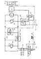
- Fig. 5 shows the system with the 'raise' mode selected; the 'raise' mode is used to bring hammer 12 to its maximum height in guide column 112 (Fig. 1).
- the lines subject to hydraulic pressure are hatched, and those subject to pressure one proximity switch 26 (Fig. 1) has been actuated are shown as broken line 218.
- the carrier/hydraulic pump 212 supplies fluid under pressure, which is allowed into the circuit by valve 214.
- Optional valve 216 may act to divert some fluid.
- Flow-control valve 208 allows the required volume of fluid therethrough, and the hydraulic motor 20 is activated.
- the pressure-reducing valve 208 and the clutch activation valve 210 operate to engage the clutch 24, which in turn activates the drum 16.
- Drum 16 winds rope 14, raising weight 12.
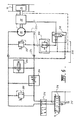
- Fig. 6 shows the circuit of hydraulic system in the 'hold' mode. Lines subject to tank pressure are shown hatched, and lines subject to load pressure are denoted by broken lines 222.
- tank pressure fluid is locked between components 220, 202, 210, 214 and 224.
- the weight/hammer 14 can be held at any point.
- FIG. 7 shows the state of the system when the 'release' mode is selected. Lines subject to pump pressure are shown hatched. Broken line 226 denoted the drain line to tank 220 at tank pressure, which is minimal.
- Fluid is supplied by carrier 212 through valves 214 at (optionally) 26.
- the pressure relief valve 208 allows a required pressure, and clutch activation valve 210 operates to disengage the clutch 22.
- the gearbox 24 and drum 16 are then free to rotate, which they do as weight 12 falls under the influence of gravity to strike tool 134 (Figs. 2 and 3). If, for some reason, the 'raise' mode is selected during the free fall of weight 12, the pressure relief valve 202 which operate to allow deceleration to occur, thus preventing damage to the motor 20 and its components.
- the apparatus 10 (which is preferably mounted on a vehicle or the like for easy transportation) is located over an area of rock or the like to be broken, preferably with the working surface 138 of tool 134 placed on the rock or the like.
- the operator selects the 'raise' mode, which operates as described hereinbefore to raise hammer 12.
- a desirable height which may be indicated by some form of visual or other indication
- the operator may select the 'hold' mode, and may then proceed to select the 'release' mode, or may go straight to the 'release' mode.
- the hammer 12 falls to strike tool 134, driving it with an impulse into the rock or the like.
- Fig. 8 is an electrical circuit diagram into which the three proximity switches 26, 27 and 29 are wired.
- the switches sense the presence or absence of the weight 12 or the pin 144, and function, through relay 31 and solenoid 33, to engage or disengage the hydraulics which raise weight 12.
- the proximity switches are arranged so that switches 26, 29 are normally closed, in series, and switch 27 is normally open in parallel. The switches activate when magnetic contact is made with weight 12 or pin 144.
- Switch 26 goes to a closed mode when the weight 12 is sensed, near the top of guide column 112, and this serves to stop the raising of the weight 12. All is in readiness for the release of the weight.
- pin 144 is not sensed by switch 29, that is, if it is not in the position shown in Fig. 1, but is in a lower (incorrect) position, the weight will not be released because switch 29 will be open. Only when the apparatus is correctly positioned will the top of pin 144 be sensed by switch 29.
- the circuit will operate the hydraulics to raise the weight 12.
- weight 12 passes switch 27 a first time, going up, it will be sensed, but will not affect the continued raising of the weight. Only when the weight 12 is sensed by switching 27 on the way down, will the circuit operate to drake drum 16, preventing overrun of the cable 14 (and 'whiplash') and minimising the impact on the base 110 of the apparatus 10.
- this invention provides apparatus for breaking rocks and the like, which is effective and safe in its operation. It is clear that the essence of the invention could be used in apparatus for other purposes, such as pile driving.
Landscapes
- Engineering & Computer Science (AREA)
- Mechanical Engineering (AREA)
- Mining & Mineral Resources (AREA)
- Percussive Tools And Related Accessories (AREA)
- Earth Drilling (AREA)
- Crushing And Grinding (AREA)
- Disintegrating Or Milling (AREA)
- Perforating, Stamping-Out Or Severing By Means Other Than Cutting (AREA)
Priority Applications (4)
| Application Number | Priority Date | Filing Date | Title |
|---|---|---|---|
| DE8686630087T DE3684782D1 (de) | 1985-11-04 | 1986-05-06 | Felsenbrechanlage. |
| AT86630087T ATE74550T1 (de) | 1985-11-04 | 1986-05-06 | Felsenbrechanlage. |
| EP86630087A EP0245572B1 (de) | 1985-11-04 | 1986-05-06 | Felsenbrechanlage |
| US07/047,482 US4838363A (en) | 1985-11-04 | 1987-05-11 | Rock-breaking apparatus |
Applications Claiming Priority (2)
| Application Number | Priority Date | Filing Date | Title |
|---|---|---|---|
| AU49381/85A AU585274B2 (en) | 1984-11-02 | 1985-11-04 | Rock breaking apparatus |
| EP86630087A EP0245572B1 (de) | 1985-11-04 | 1986-05-06 | Felsenbrechanlage |
Publications (3)
| Publication Number | Publication Date |
|---|---|
| EP0245572A2 true EP0245572A2 (de) | 1987-11-19 |
| EP0245572A3 EP0245572A3 (en) | 1989-05-17 |
| EP0245572B1 EP0245572B1 (de) | 1992-04-08 |
Family
ID=25628654
Family Applications (1)
| Application Number | Title | Priority Date | Filing Date |
|---|---|---|---|
| EP86630087A Expired - Lifetime EP0245572B1 (de) | 1985-11-04 | 1986-05-06 | Felsenbrechanlage |
Country Status (4)
| Country | Link |
|---|---|
| US (1) | US4838363A (de) |
| EP (1) | EP0245572B1 (de) |
| AT (1) | ATE74550T1 (de) |
| DE (1) | DE3684782D1 (de) |
Cited By (1)
| Publication number | Priority date | Publication date | Assignee | Title |
|---|---|---|---|---|
| WO2007126306A3 (en) * | 2006-05-03 | 2010-09-02 | Jacobus Maria Josef Hofland | Method for breaking up steel slag blocks by gravity |
Families Citing this family (11)
| Publication number | Priority date | Publication date | Assignee | Title |
|---|---|---|---|---|
| US5363835A (en) * | 1992-08-31 | 1994-11-15 | Rocktec Limited | Nose block assembly |
| US6257352B1 (en) | 1998-11-06 | 2001-07-10 | Craig Nelson | Rock breaking device |
| KR200207572Y1 (ko) * | 1998-12-04 | 2001-01-15 | 이원해 | 유압식 착암기의 방음 방진 장치 |
| US6117215A (en) * | 1999-04-05 | 2000-09-12 | Westvaco Corporation | Electro-magnetic rapper wear guide |
| NZ522157A (en) * | 2002-10-21 | 2005-09-30 | Rocktec Ltd | a powered hammer device |
| EP1713978A2 (de) * | 2004-01-29 | 2006-10-25 | Clark Equipment Company | Fallhammer |
| US7503628B2 (en) * | 2006-09-01 | 2009-03-17 | Hall David R | Formation breaking assembly |
| US8061439B2 (en) * | 2007-10-16 | 2011-11-22 | Craig Nelson | Isolator plate assembly for rock breaking device |
| US9089995B2 (en) | 2007-10-16 | 2015-07-28 | Craig Nelson | Isolator plate assembly for rock breaking device |
| WO2014169917A1 (en) * | 2013-04-19 | 2014-10-23 | Fractum 2012 Aps | A hammering device and a method for operating a hammering device |
| JP7210452B2 (ja) * | 2017-07-24 | 2023-01-23 | 古河ロックドリル株式会社 | 液圧式打撃装置 |
Family Cites Families (9)
| Publication number | Priority date | Publication date | Assignee | Title |
|---|---|---|---|---|
| DE1603852C3 (de) * | 1968-01-29 | 1975-12-04 | Hilti Ag, Schaan (Liechtenstein) | Abfangvorrichtung für den Eintreibkolben eines pulverkraftbetriebenen Bolzensetzgerätes |
| US3817091A (en) * | 1971-05-11 | 1974-06-18 | L Frederick | Pile driver drive cap |
| US3889765A (en) * | 1972-06-08 | 1975-06-17 | Mobile Drilling Co Inc | Earth sampling apparatus |
| AU522890B2 (en) * | 1976-08-24 | 1982-07-01 | Bennetto, John | Rock breaking apparatus |
| US4103747A (en) * | 1977-01-14 | 1978-08-01 | Finney James L | Buffer spring for an impact tool |
| GB2047605B (en) * | 1979-04-26 | 1983-02-16 | Kone Oy | Percussion tool |
| DE3107140C2 (de) * | 1981-02-26 | 1985-11-28 | Mannesmann AG, 4000 Düsseldorf | Rammvorrichtung mit einer Schlagvorrichtung |
| AU536689B2 (en) * | 1981-11-24 | 1984-05-17 | John Bennetto | Rock breaking apparatus |
| DE8514700U1 (de) * | 1985-05-15 | 1985-09-19 | Peiner Maschinen- Und Schraubenwerke Ag, 3150 Peine | Arbeitsgerät zum Zerbrechen von Felsgestein |
-
1986
- 1986-05-06 AT AT86630087T patent/ATE74550T1/de not_active IP Right Cessation
- 1986-05-06 DE DE8686630087T patent/DE3684782D1/de not_active Expired - Lifetime
- 1986-05-06 EP EP86630087A patent/EP0245572B1/de not_active Expired - Lifetime
-
1987
- 1987-05-11 US US07/047,482 patent/US4838363A/en not_active Expired - Lifetime
Cited By (1)
| Publication number | Priority date | Publication date | Assignee | Title |
|---|---|---|---|---|
| WO2007126306A3 (en) * | 2006-05-03 | 2010-09-02 | Jacobus Maria Josef Hofland | Method for breaking up steel slag blocks by gravity |
Also Published As
| Publication number | Publication date |
|---|---|
| US4838363A (en) | 1989-06-13 |
| ATE74550T1 (de) | 1992-04-15 |
| DE3684782D1 (de) | 1992-05-14 |
| EP0245572A3 (en) | 1989-05-17 |
| EP0245572B1 (de) | 1992-04-08 |
Similar Documents
| Publication | Publication Date | Title |
|---|---|---|
| US4838363A (en) | Rock-breaking apparatus | |
| US4850737A (en) | Hydraulic spring vehicle barricade and hydraulic circuit therefor | |
| EP2321472B1 (de) | Verfahren und vorrichtung zum pfahleintreiben unter wasser | |
| KR100255698B1 (ko) | 땅속에 말뚝을 박거나 땅속으로부터 이를 뽑아내기 위한 방법 및 장치 | |
| US4576508A (en) | Bollard trafficway barrier and vehicle arrest system | |
| US8181568B1 (en) | Bulk bag conditioning system | |
| US4405020A (en) | Automatic drive hammer system | |
| US20160076216A1 (en) | Hammering device and a method for operating a hammering device | |
| US3842917A (en) | Pumped evacuated tube water hammer pile driver | |
| US5408768A (en) | Impact hammer cylinder | |
| CA1289927C (en) | Rock-breaking apparatus | |
| US5404959A (en) | Drill rig safety shutdown device | |
| KR102178546B1 (ko) | 케이싱 일체형 드롭해머장치 | |
| JPH01501327A (ja) | インパクトリッパの制御システム | |
| US5542180A (en) | Heavy duty shear with anti-jam feature | |
| US4333492A (en) | Liquid inertia tool | |
| US3797759A (en) | Crusher adjusting system | |
| US6192782B1 (en) | Torque control means for hydraulic motor | |
| US3015365A (en) | Sliding weight holepuncher for the installation of wellpoints | |
| KR100645732B1 (ko) | 저압전용 배관 천공장치 | |
| KR102872546B1 (ko) | 대용량 냉면 육수 교반기 | |
| KR102099320B1 (ko) | 해머안전장치를 가진 항타장치 | |
| US10513832B2 (en) | Pneumatic piling hammer for submersion pilings | |
| NL8105722A (nl) | Verbeterde poot-afsluiting. | |
| JPH03262838A (ja) | 深掘り掘削機の保安機構 |
Legal Events
| Date | Code | Title | Description |
|---|---|---|---|
| PUAI | Public reference made under article 153(3) epc to a published international application that has entered the european phase |
Free format text: ORIGINAL CODE: 0009012 |
|
| AK | Designated contracting states |
Kind code of ref document: A2 Designated state(s): AT BE CH DE FR GB IT LI LU NL SE |
|
| PUAL | Search report despatched |
Free format text: ORIGINAL CODE: 0009013 |
|
| AK | Designated contracting states |
Kind code of ref document: A3 Designated state(s): AT BE CH DE FR GB IT LI LU NL SE |
|
| 17P | Request for examination filed |
Effective date: 19891020 |
|
| 17Q | First examination report despatched |
Effective date: 19900917 |
|
| GRAA | (expected) grant |
Free format text: ORIGINAL CODE: 0009210 |
|
| AK | Designated contracting states |
Kind code of ref document: B1 Designated state(s): AT BE CH DE FR GB IT LI LU NL SE |
|
| PG25 | Lapsed in a contracting state [announced via postgrant information from national office to epo] |
Ref country code: SE Effective date: 19920408 Ref country code: NL Effective date: 19920408 Ref country code: LI Effective date: 19920408 Ref country code: CH Effective date: 19920408 Ref country code: BE Effective date: 19920408 Ref country code: AT Effective date: 19920408 |
|
| REF | Corresponds to: |
Ref document number: 74550 Country of ref document: AT Date of ref document: 19920415 Kind code of ref document: T |
|
| ET | Fr: translation filed | ||
| ITF | It: translation for a ep patent filed | ||
| REF | Corresponds to: |
Ref document number: 3684782 Country of ref document: DE Date of ref document: 19920514 |
|
| PG25 | Lapsed in a contracting state [announced via postgrant information from national office to epo] |
Ref country code: LU Free format text: LAPSE BECAUSE OF NON-PAYMENT OF DUE FEES Effective date: 19920531 |
|
| REG | Reference to a national code |
Ref country code: CH Ref legal event code: PL |
|
| NLV1 | Nl: lapsed or annulled due to failure to fulfill the requirements of art. 29p and 29m of the patents act | ||
| PLBE | No opposition filed within time limit |
Free format text: ORIGINAL CODE: 0009261 |
|
| STAA | Information on the status of an ep patent application or granted ep patent |
Free format text: STATUS: NO OPPOSITION FILED WITHIN TIME LIMIT |
|
| 26N | No opposition filed | ||
| ITTA | It: last paid annual fee | ||
| REG | Reference to a national code |
Ref country code: GB Ref legal event code: IF02 |
|
| PGFP | Annual fee paid to national office [announced via postgrant information from national office to epo] |
Ref country code: GB Payment date: 20050425 Year of fee payment: 20 |
|
| PG25 | Lapsed in a contracting state [announced via postgrant information from national office to epo] |
Ref country code: IT Free format text: LAPSE BECAUSE OF NON-PAYMENT OF DUE FEES;WARNING: LAPSES OF ITALIAN PATENTS WITH EFFECTIVE DATE BEFORE 2007 MAY HAVE OCCURRED AT ANY TIME BEFORE 2007. THE CORRECT EFFECTIVE DATE MAY BE DIFFERENT FROM THE ONE RECORDED. Effective date: 20050506 |
|
| PGFP | Annual fee paid to national office [announced via postgrant information from national office to epo] |
Ref country code: DE Payment date: 20050510 Year of fee payment: 20 |
|
| PGFP | Annual fee paid to national office [announced via postgrant information from national office to epo] |
Ref country code: FR Payment date: 20050512 Year of fee payment: 20 |
|
| PG25 | Lapsed in a contracting state [announced via postgrant information from national office to epo] |
Ref country code: GB Free format text: LAPSE BECAUSE OF EXPIRATION OF PROTECTION Effective date: 20060505 |
|
| REG | Reference to a national code |
Ref country code: GB Ref legal event code: PE20 |