EP0245556A2 - Spiegelsystem, um die hintere Seite eines Gegenstandes zu beobachten - Google Patents
Spiegelsystem, um die hintere Seite eines Gegenstandes zu beobachten Download PDFInfo
- Publication number
- EP0245556A2 EP0245556A2 EP86307486A EP86307486A EP0245556A2 EP 0245556 A2 EP0245556 A2 EP 0245556A2 EP 86307486 A EP86307486 A EP 86307486A EP 86307486 A EP86307486 A EP 86307486A EP 0245556 A2 EP0245556 A2 EP 0245556A2
- Authority
- EP
- European Patent Office
- Prior art keywords
- mirror
- mirrors
- observer
- mirror system
- subject
- Prior art date
- Legal status (The legal status is an assumption and is not a legal conclusion. Google has not performed a legal analysis and makes no representation as to the accuracy of the status listed.)
- Withdrawn
Links
- BQCADISMDOOEFD-UHFFFAOYSA-N Silver Chemical compound [Ag] BQCADISMDOOEFD-UHFFFAOYSA-N 0.000 description 2
- 239000011521 glass Substances 0.000 description 2
- 229910052709 silver Inorganic materials 0.000 description 2
- 239000004332 silver Substances 0.000 description 2
- 230000005540 biological transmission Effects 0.000 description 1
- 210000004209 hair Anatomy 0.000 description 1
- 210000003128 head Anatomy 0.000 description 1
- 238000012856 packing Methods 0.000 description 1
Images

Classifications
-
- A—HUMAN NECESSITIES
- A45—HAND OR TRAVELLING ARTICLES
- A45D—HAIRDRESSING OR SHAVING EQUIPMENT; EQUIPMENT FOR COSMETICS OR COSMETIC TREATMENTS, e.g. FOR MANICURING OR PEDICURING
- A45D42/00—Hand, pocket, or shaving mirrors
- A45D42/18—Manifold reflecting mirrors
-
- A—HUMAN NECESSITIES
- A47—FURNITURE; DOMESTIC ARTICLES OR APPLIANCES; COFFEE MILLS; SPICE MILLS; SUCTION CLEANERS IN GENERAL
- A47G—HOUSEHOLD OR TABLE EQUIPMENT
- A47G1/00—Mirrors; Picture frames or the like, e.g. provided with heating, lighting or ventilating means
- A47G1/02—Mirrors used as equipment
- A47G1/04—Multi-part mirrors
-
- A—HUMAN NECESSITIES
- A47—FURNITURE; DOMESTIC ARTICLES OR APPLIANCES; COFFEE MILLS; SPICE MILLS; SUCTION CLEANERS IN GENERAL
- A47G—HOUSEHOLD OR TABLE EQUIPMENT
- A47G1/00—Mirrors; Picture frames or the like, e.g. provided with heating, lighting or ventilating means
- A47G1/16—Devices for hanging or supporting pictures, mirrors, or the like
- A47G1/24—Appliances for adjusting pictures, mirrors, or the like, into a desired position, especially inclined
Definitions
- the present invention relates to a mirror wherein an image of the rear side of an observer can be easily seen.
- a mirror system comprising a front mirror and respective wing mirrors at both sides thereof is used.
- This three-mirror arrangement is so constituted that, when the subject faces the front mirror, the front image and the side images of the subject are formed by the front mirror and the wing mirrors respectively.
- the present invention provides a mirror system comprising three or more mirrors, characterised in that said mirrors are supported to define a folded ray path in the form of a closed loop such that a subject interposed in said ray path can see his rear view in one of said mirrors, preferably, there are four of said mirrors.
- one of said mirrors is of substantially the full height and width of a person and forms a substantially complete rear view of the subject in another of said mirrors when said subject is interposed said ray path.
- the system comprises a first mirror, a second mirror, a third mirror, a fourth mirror, and a base to support respective mirrors integrally.
- Respective mirrors stand contiguous to each other in sequence, and mirror surfaces of the contiguous mirrors are perpendicular to each other and mirror surfaces of every other contiguous mirrors are arranged in opposition.
- incident ray to the first mirror in the horizontal incident angle 45° is projected through the second mirror and the third mirror onto the fourth mirror so as to attain the above object.
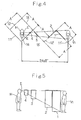
- the virtual image VI is projected onto the second mirror (2) remote from the first mirror (1) by distance L3 between the reflecting points, and virtual image V2 is produced at position of distance L4 being equal to sum of the distance L2 and the distance L3.
- virtual image V2 is projected onto the third mirror (3) remote from the second mirror (2) by distance L5 between the reflecting points, and virtual image V3 is produced at position of distance L6 being equal to sum of the distance L4 and the distance L5.
- virtual image V3 is projected onto the fourth mirror (4) remote from the third mirror (3) by distance L7 between the reflecting points, and virtual image V4 is produced at position of distance L8 being equal to sum of the distance L6 and the distance L7, thereby the rear image of the observer (H) is projected onto the fourth mirror (4) in front of the observer (H).
- the rear image becomes the same phase at lateral sides by the reflection of four times, and becomes the projection image in the same direction as that of the observer (H).
- the subject himself can observe the rear image which is accurate and seen as another person sees the back configuration of the subject.
- reference numeral 1 designates a first mirror of the mirror to enable projection of rear side of an observer.
- the first mirror 1 of the embodiment is formed in lateral size 70 cm and longitudinal size 150cm so that whole rear side of the observer can be projected with a prescribed spacing.
- a second mirror 2, a third mirror 3 and a fourth mirror 4 in the embodiment are set respectively in lateral size to 0.9 times, 0.6 times and 0.45 times of that of the first mirror 1 and in longitudinal size to 0.8 times, 0.45 times and 0.25 times of that of the first mirror I.
- Size of the mirrors 1, 2, 3 and 4 is determined by equivalent position of the projection image when the four mirrors 1, 2, 3 and 4 are deemed as transmission bodies.
- Virtual image V1 projected onto the first mirror 1 is positioned at distance 2A/2 in front of the observer H, and mounting positions of the mirror 1, 2, 3 and 4 and lateral size and longitudinal size of the mirrors 1, 2, 3 and 4 are determined by intersections between the line connecting the virtual image VI to the position E of eyes and the developed reference lines 11', 12', 13' and 14.
- silver surface is formed on rear surface of a glass plate having thickness 5mm, and lining is further applied thereto.
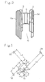
- a base 5 in the embodiment is a frame body formed by tubular members. As shown if Fig. 1, bottom portion of the base 5 is constituted along the reference lines 11, 12, 13 and 14 to form square, and a polyhedron space is formed at inside of the square.
- the base 5 has support members 5a, 5b, 5c and 5d formed at prescribed positions, and an open surface 6 for entering or leaving to the inside space of the base 5 is formed on one side of the support members 5a, 5b, 5c and 5d.
- the mirrors 1, 2, 3 and 4 each mirror surface directed towards the inside, are fixed and supported respectively on the support members 5a, 5b, 5c and 5d.
- the first mirror 1 is opposed to the third mirror 3 and also the second mirror 2 is opposed to the fourth mirror 4, and the mirrors 1, 2, 3 and 4 are connected by luminous path P so that the center of the lateral length of each mirror has the incident angle and the reflecting angle of 45° respectively.
- lateral size and longitudinal size of the four mirrors 1, 2, 3 and 4 become smaller in sequence in the above embodiment, for example, only lateral size of the four mirrors 1, 2, 3 and 4 or only longitudinal sizethereof may be made smaller in sequence.
- Lateral size of the mirror 1 and 2 may be made equal and lateral size of the mirrors 3 and 4 may be made equal to each other and smaller than that of the mirrors 1 and 2, and longitudinal size of the mirrors 1, 2, 3 and 4 may be made smaller in sequence.
- the four mirrors, 1, 2, 3 and 4 may be of the same size, and various combination of the mirror size may be taken corresponding to whole amount of the observer and the mirror as well as design of the mirror to enable projection of rear side of the observer.
- bottom space constituted by the reference lines 11, 12, 13 and 14 may be of rectangular form.
- the base 5 may be provided with pivoral members 7 at bent portions in Fig. 1 and the support members 5a, 5b, 5c and 5d may be folded so that the packing volume during transportation is made compact.
- mirrors 1, 2, 3 and 4 of rear surface reflection type In place of the mirrors 1, 2, 3 and 4 of rear surface reflection type in the embodiment, mirrors of front surface reflection type may be used.
- the mirror of front surface reflection type has effect of suppressing obscureness of the reflection image which is inevitable in the mirror of rear surface reflection type.
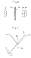
- the obscureness of the reflection image will be described referring to Figs. 6 and 7.
- a rear surface reflecting mirror 21 with a reflecting surface 21a formed on rear side of a glass plate 4 - 5% of the incident ray is reflected on the surface of the mirror 21 and the residual is reflected on the reflecting surface 21a.
- rear surface reflecting image R1 and front surface reflecting image R2 lie one upon another in the front and rear direction as shown in Fig. 6 and therefore existence of the front surface reflecting image R2 becomes no problem.
- the rear surface reflecting image Rl and the front surface reflecting image R2 do not lie one upon another, but the front surface reflecting image R2 appears as shown in Fig. 7 and makes the rear surface reflecting image R1 obscure in proportion to the distance between the observer H and the object H to be observed.
- the obscureness of the rear surface reflecting image R1 due to the front surface reflecting image R2 can be removed using a front surface reflecting mirror with silver surface formed on the mirror surface. Consequently, one or plural pieces among the mirrors 1, 2, 3 and 4 may be replaced by the front reflecting mirrors so that a rear side mirror to obtain clear reflecting image can be formed.
- the four mirrors may be made smaller in sequence as above described.
- the invention is not limited to mirror systems incorporating an even number of mirrors (which form a real image of the rear view of the subject), but also includes within its scope systems incorporating an odd number of mirrors, which form a virtual image of the rear view of the subject.
Landscapes
- Mirrors, Picture Frames, Photograph Stands, And Related Fastening Devices (AREA)
- Optical Elements Other Than Lenses (AREA)
- Lenses (AREA)
Applications Claiming Priority (2)
| Application Number | Priority Date | Filing Date | Title |
|---|---|---|---|
| JP1986073216U JPS62185570U (de) | 1986-05-15 | 1986-05-15 | |
| JP73216/86U | 1986-05-15 |
Publications (2)
| Publication Number | Publication Date |
|---|---|
| EP0245556A2 true EP0245556A2 (de) | 1987-11-19 |
| EP0245556A3 EP0245556A3 (de) | 1989-06-14 |
Family
ID=13511748
Family Applications (1)
| Application Number | Title | Priority Date | Filing Date |
|---|---|---|---|
| EP86307486A Withdrawn EP0245556A3 (de) | 1986-05-15 | 1986-09-30 | Spiegelsystem, um die hintere Seite eines Gegenstandes zu beobachten |
Country Status (5)
| Country | Link |
|---|---|
| EP (1) | EP0245556A3 (de) |
| JP (1) | JPS62185570U (de) |
| KR (1) | KR920002777Y1 (de) |
| AU (1) | AU6306086A (de) |
| DE (1) | DE3635630A1 (de) |
Cited By (3)
| Publication number | Priority date | Publication date | Assignee | Title |
|---|---|---|---|---|
| WO2006075866A1 (en) * | 2005-01-12 | 2006-07-20 | Chan-Hak Lee | Mirror system |
| RU2292828C2 (ru) * | 2005-04-22 | 2007-02-10 | Виктор Иосифович Заев | Устройство для демонстрации трехмерного изображения внешнего вида человека |
| WO2012177230A1 (ru) * | 2011-06-20 | 2012-12-27 | Golovatskyy Dmytriy Vasilyevich | Трехмерная примерочная |
Families Citing this family (2)
| Publication number | Priority date | Publication date | Assignee | Title |
|---|---|---|---|---|
| KR101941788B1 (ko) * | 2017-11-28 | 2019-01-24 | 김동현 | 뒤태 거울 장치 |
| KR200491241Y1 (ko) * | 2018-07-06 | 2020-03-09 | 대흥물산 주식회사 | 휠이 부착된 미닫이형 방충망 장치 |
Family Cites Families (6)
| Publication number | Priority date | Publication date | Assignee | Title |
|---|---|---|---|---|
| DE599183C (de) * | 1934-06-27 | Anton Kschier | Spiegel mit mehreren im Winkel zueinander angebrachten Spiegeln | |
| US1422685A (en) * | 1920-06-05 | 1922-07-11 | Fitchet Charles Lee | Mirror structure |
| US2670660A (en) * | 1951-06-19 | 1954-03-02 | William Miller Instr Inc | Multiple reflection indication for moving mirror instruments |
| FR2267727A1 (en) * | 1974-04-19 | 1975-11-14 | Lechevallier Maurice | Adjustment device for mirrors showing silhouette - has variable linkage triangular frame supporting three mirrors |
| JPS6040657B2 (ja) * | 1976-10-12 | 1985-09-12 | 株式会社東芝 | インデックス方式カラ−受像管の螢光面形成方法 |
| GB2137085B (en) * | 1983-01-12 | 1986-11-26 | Creation Electrical Machine Co | A mirror assembly |
-
1986
- 1986-05-15 JP JP1986073216U patent/JPS62185570U/ja active Pending
- 1986-08-14 KR KR2019860012300U patent/KR920002777Y1/ko not_active Expired
- 1986-09-23 AU AU63060/86A patent/AU6306086A/en not_active Abandoned
- 1986-09-30 EP EP86307486A patent/EP0245556A3/de not_active Withdrawn
- 1986-10-20 DE DE19863635630 patent/DE3635630A1/de not_active Ceased
Cited By (3)
| Publication number | Priority date | Publication date | Assignee | Title |
|---|---|---|---|---|
| WO2006075866A1 (en) * | 2005-01-12 | 2006-07-20 | Chan-Hak Lee | Mirror system |
| RU2292828C2 (ru) * | 2005-04-22 | 2007-02-10 | Виктор Иосифович Заев | Устройство для демонстрации трехмерного изображения внешнего вида человека |
| WO2012177230A1 (ru) * | 2011-06-20 | 2012-12-27 | Golovatskyy Dmytriy Vasilyevich | Трехмерная примерочная |
Also Published As
| Publication number | Publication date |
|---|---|
| KR920002777Y1 (ko) | 1992-05-01 |
| JPS62185570U (de) | 1987-11-25 |
| DE3635630A1 (de) | 1987-11-19 |
| EP0245556A3 (de) | 1989-06-14 |
| KR870017914U (ko) | 1987-12-21 |
| AU6306086A (en) | 1987-11-19 |
Similar Documents
| Publication | Publication Date | Title |
|---|---|---|
| EP0734541B1 (de) | Gerät zur abbildung eines bildes | |
| US5418584A (en) | Retroreflective array virtual image projection screen | |
| EP0009332B1 (de) | Blickfeldanzeige | |
| US3447854A (en) | Three-dimensional viewer | |
| US5477385A (en) | Optical magnifying apparatus | |
| JPH10246865A5 (de) | ||
| JPH03113412A (ja) | ヘッドアップディスプレイ装置 | |
| US4545655A (en) | Optical viewing system | |
| JPH0416485U (de) | ||
| US20210141241A1 (en) | Device for the dematerialised aerial projection of a digital image or a sequence of digital images, in particular an auto-stereoscopic image or a sequence of autostereoscopic images | |
| US4526444A (en) | Viewfinder apparatus | |
| EP0245556A2 (de) | Spiegelsystem, um die hintere Seite eines Gegenstandes zu beobachten | |
| JPH0135551B2 (de) | ||
| US4235515A (en) | Stereoscopic viewing system | |
| JP7602241B2 (ja) | 空中像形成装置 | |
| US4333707A (en) | Method of image enhancement | |
| US5058990A (en) | Stereoscopic viewer and view panels therefor | |
| JP2001108939A (ja) | 画像表示装置およびスクリーン | |
| GB2179716A (en) | Head-up displays | |
| EP0766860B1 (de) | Abbildungsvorrichtung | |
| US6871957B2 (en) | Autostereoscopic display for multiple viewers | |
| US4991331A (en) | Display assembly | |
| GB2221054A (en) | Viewer for stereoscopic images | |
| JP2000275736A (ja) | 指向性反射スクリーンおよび画像表示装置 | |
| US313899A (en) | Aaeon k |
Legal Events
| Date | Code | Title | Description |
|---|---|---|---|
| PUAI | Public reference made under article 153(3) epc to a published international application that has entered the european phase |
Free format text: ORIGINAL CODE: 0009012 |
|
| AK | Designated contracting states |
Kind code of ref document: A2 Designated state(s): DE FR GB IT |
|
| PUAL | Search report despatched |
Free format text: ORIGINAL CODE: 0009013 |
|
| RHK1 | Main classification (correction) |
Ipc: A47G 1/04 |
|
| AK | Designated contracting states |
Kind code of ref document: A3 Designated state(s): DE FR GB IT |
|
| STAA | Information on the status of an ep patent application or granted ep patent |
Free format text: STATUS: THE APPLICATION IS DEEMED TO BE WITHDRAWN |
|
| 18D | Application deemed to be withdrawn |
Effective date: 19891215 |
|
| RIN1 | Information on inventor provided before grant (corrected) |
Inventor name: NISHIMOTO, MITSUO |