EP0245513B1 - Vacuum interrupter - Google Patents
Vacuum interrupter Download PDFInfo
- Publication number
- EP0245513B1 EP0245513B1 EP86906924A EP86906924A EP0245513B1 EP 0245513 B1 EP0245513 B1 EP 0245513B1 EP 86906924 A EP86906924 A EP 86906924A EP 86906924 A EP86906924 A EP 86906924A EP 0245513 B1 EP0245513 B1 EP 0245513B1
- Authority
- EP
- European Patent Office
- Prior art keywords
- electrode
- high resistance
- resistance areas
- electrodes
- vacuum interrupter
- Prior art date
- Legal status (The legal status is an assumption and is not a legal conclusion. Google has not performed a legal analysis and makes no representation as to the accuracy of the status listed.)
- Expired - Lifetime
Links
Images


Classifications
-
- H—ELECTRICITY
- H01—ELECTRIC ELEMENTS
- H01H—ELECTRIC SWITCHES; RELAYS; SELECTORS; EMERGENCY PROTECTIVE DEVICES
- H01H33/00—High-tension or heavy-current switches with arc-extinguishing or arc-preventing means
- H01H33/60—Switches wherein the means for extinguishing or preventing the arc do not include separate means for obtaining or increasing flow of arc-extinguishing fluid
- H01H33/66—Vacuum switches
- H01H33/664—Contacts; Arc-extinguishing means, e.g. arcing rings
- H01H33/6644—Contacts; Arc-extinguishing means, e.g. arcing rings having coil-like electrical connections between contact rod and the proper contact
Definitions
- the present invention relates to a vacuum interrupter of high mechanical strength in which an arc is stably and uniformly distributed on surfaces of electrodes, and electro-magnetic repulsive force generated at the time of applying a large current is reduced.
- a vacuum interrupter comprises a vacuum container (1) closed with end plates (21), (22), a pair of electrodes (30), (40) facing to each other and conductive rods (5), (6) provided through said end plates (5), (6), and in which a bellows (7) is mounted on one electrode (6) to be movable in the axial direction without affecting air-tightness, and said electrodes (30), (40) are detachable and can be connected to each other. Further, a shield (8) is provided to acquire evaporated metals. Said conductive rod (6) is driven by a drive mechanism not shown for switching operation of an electric circuit.
- interruption performance can be improved by stably and uniformly distributing the arc on the surfaces of the electrodes by applying a magnetic field in parallel to the arc, particularly when interrupting a large current arc. It is also known that when said electrodes (30), (40) are in a closed state, an electro-magnetic repulsive force is generated due to the large current application, and a small gap is formed between said electrodes (30), (40), thereby generating a local arc which brings about welding or deteriorates the electrode surfaces, finally lowering withstand voltage performance.
- Fig. 2(a)-(c) Japanese laid-open Patent Publication (unexamined) No.57-3327.
- Fig. 2 (a) is a side view showing an example of arrangement of electrodes in such prior vacuum interrupter
- Fig. 2 (b) is a plan view in the direction of the arrow b-b
- Fig. 2 (c) is a plan view in the direction of the arrow c-c.
- reference numerals (50), (60) designate bridge conductors respectively fixed on the ends of the bridge conductors (5), (6). These bridge conductors (5), (6) are rectangular and projecting parts (51), (52), (61), (62) are respectively formed on both ends thereof. Numerals (30), (40) disignate a pair of electrodes connected electrically to each bridge conductor (50), (60) on their outer peripheral back sides respectively.
- circular arc-shaped grooves (33), (34), (43), (44) serving as high resistance areas are formed on each electrode (30), (40) by cutting at required distances, thus circular arc-shaped electrode parts (31), (32) and (41), (42) serving as outside parts of the electrodes partitioned by these grooves (33), (34) and (43), (44) are formed.
- Said bridge conductor (50) is so arranged as to cross the grooves (43), (44), and the projecting parts (51), (52) and (61), (62) are electrically and mechanically connected to substantially central parts of said circular arc-shaped electrode parts (31), (32) and (41), (41).
- Gaps between said bridge conductors (50), (60) and the electrodes (30), (40) are desired to be as small as possible, but it is necessary that the gaps are in a range in which the electrodes (30), (40) do not come in contact with the bridge conductors (50), (60) when the electrodes are butted to each other bringing about elastic deformation due to a mechanical force applied.
- the aforesaid electrode (30) and the bridge conductor (50) are respectively of the same configuration as the electrode (40) and the bridge conductor (60), but the electrode (40) and the bridgre conductor (60) are so arranged as to face to the electrode (30) and the brdige conductor (50) by 90° respectively being deviated by 90° therefrom.
- the (51) ⁇ (31) ⁇ B ⁇ A is a loop formed by the electrode itself, the loop is near the point A and a strong axial magnetic field is generated.
- the current i passes from the point A' of the other electrode (40) to the conductive rod (6) by way of a gap C between the grooves (43), (44) of the electrode (40), the circular arc-shaped electrode part (41), the projecting part (61) and the bridge conductor (60). That is, one turn is further formed by a current loop A' ⁇ C ⁇ (41) ⁇ (61) ⁇ (60) ⁇ (6) is further formed, and a magnetic field of the same axial direction as the foregoing loop is generated.
- a strong combined magnetic flux in the axial direction acts in parallel to the arc A-A' as indicated by the arrow ⁇ in Fig. 2(a), effectively preventing emission and diffusion of ionized metals from the arc to outside, acquiring a sufficient amount of plasma particles and stabilizing the arc.
- an electro-magnetic repulsive force is generated at the contact points due to concentration of the current and acts to separate the electrodes 30, 40, but since the current direction from the projecting part 51 to the tap B in the electrode 30 is same as that from the gap C to the projecting part 61 in the other electrode 40, the circular arc-shaped electrode parts 31, 41 are strongly attracted to each other.
- the electrode contact force applied to said electrodes 30, 40 can be greatly reduced by means of the operation mechanism not shown, and the operation mechanism can be small-sized and light-weight.
- DE-A-3416368 discloses a vacuum interrupter generally similar to that shown in figure 2 but additionally provided with rectilinear slots in the electrode extending radially inwards from the circular arc-shaped grooves serving as high resistance areas, in order to direct and concentrate the current flow path and enhance the magnetic field generated, while reducing eddy currents.
- the object of the invention is to provide electrode structures for vacuum interrupters, in which the interrupting performance is still further improved relative to the prior art.
- a vacuum interrupter for opening and closing a current passage by a pair of electrodes which are incorporated in a vacuum container, connectable to and separable from each other and respectively mounted on conductive rods, wherein at least one of said pair of electrodes is provided with first high resistance areas formed passing through from a back side towards a contact surface thereof at specified distances from a peripheral edge of the electrode and facing each other, and second high resistance areas extending from ends of the first high resistance areas towards the centre of said electrode and not connected to each other, and wherein outside parts of the electrode between the first high resistance areas and said peripheral edge are electrically connected to said conductive rod on said back side of the electrode by way of a bridge conductor (50) arranged over the first high resistance areas, characterised by annular third high resistance areas (59) formed from the first high resistance areas inside the electrode to said peripheral edge of the electrode.
- a vacuum interrupter for opening and closing a current passage by a pair of electrodes which are incorporated in a vacuum container, connectable to and separable from each other and respectively mounted on conductive rods, wherein at least one of said pair of electrodes comprises at least one first high resistance area formed passing through from a facing surface to a back side thereof at specified distances from a peripheral edge of the electrode and facing each other, and a bridge conductor arranged over the first high resistance areas and electrically connecting outside parts of the electrode between the first high resistance areas and said peripheral edge to said conductive rod on said back side of the electrode, characterised by a second high resistance area formed inside the first high resistance area or areas of said electrode and passing through said electrode connecting an annular high resistance area of which the outer diameter is D1 on the back side of the electrode to an annular high resistance area (107b) of which the outer diameter is D2 in the facing sides of the electrode where D1>D2, a contact (113, 133) projecting in the form of a ring and of
- Figure 3 (a) is a side view showing an electrode structure of a vacuum interrupter
- Fig. 3 (b) is a plan view in the direction of the arrow b-b in Figure 3
- Figure 3 (b) is a plan view in the direction of the arrow b-b in Fig. 3 (a)
- Fig. 3 (c) is a plan view in the direction of the arrow c-c in Fig. 3 (a).
- reference numberals 33, 34, 43, 44 denote high resistance areas formed on each electrode 30, 40 passing through from the contact surface to the back side thereof at specified distances from peripheral edges of the electrode 30, 40, and the high resistance areas are arranged symmetrical to the center of each electrode forming a pair of grooves not connected to each other.
- Numerals 35 to 38, 45 to 48 denote second high resistance areas extending from both ends of the first high resistance areas 33, 34, 43, 44 towards the center of each electrode 30, 40, and the second high resistance areas are linear grooves formed substantially perpendicular to bridge conductors 50, 60.
- Each electrode 30, 40 is partitioned by the first and second high resistance areas 33 to 38, 45 to 48, thereby current paths 53, 54, 55, 56 towards outside parts 31, 32, 41, 42 of the electrodes 30, 40 and center parts thereof are formed.
- the width of each current path 53 to 56 is narrower than that of the bridge conductors 50, 60.
- the bridge conductors 50, 60 are arranged over the first high resistance areas 33, 34, 41, 42 to electrically and mechanically connect the outside parts 31, 32, 41, 42 to conductive rods 5, 6.
- the electrode 30 and the bridge conductor 50 are of the same configuration as the electrode 40 and the bridge conductor 50 respectively, but the electrode 40 and the bridge conductor 60 are so arranged as to face to the electrode 30 and the bridge conductor 50 respectively being deviated by 90° therefrom.
- an arc is formed between the electrodes 30, 40.
- a current i passes from the conductive rod 5 towards the conductive rod 6 and the arc is formed between a point A of one electrode 30 and a point A' of the other electrode 40, the current i passes from the conductive rod 5 to the arc point A by way of the bridge conductor 50, the projecting part 51, the outside part 31 and the current passage 53. That is, a complete one turn is formed by a current loop 50 ⁇ 51 ⁇ 31 ⁇ 53 ⁇ A, and wherein since the 51 ⁇ 31 ⁇ 53 ⁇ A is a loop formed by the electrode itself and situated near the arc point A, a strong axial magnetic field is generated.
- the current i passes from the other point A' of the electrode 40 to the conductive rod 6 by way of the current passage 55, the outside part 41, the projecting part 61 and the bridge conductor 60. That is, a complete one turn is formed by the current loop A' ⁇ 55 ⁇ 41 ⁇ 61 ⁇ 60 ⁇ 6 and the same axial magnetic field as the foregoing current loop is formed.
- a strong combined axial magnetic flux acts in parallel to the arc A-A' indicated by the arrow ⁇ in Fig. 3 (a), emission and diffusion of ionized metals to outside are effectively prevented and the arc is stabilized by acquiring a sufficient amount of plasma particles.
- Fig. 4 a, b shows a thin electrode structure attained by interposing a reinforcing member 57 between the bridge conductor 50 and the electrode, considering that electrode materials of high conductivity such as copper, silver used in general have disadvantages in view of mechanical strength and cost saving.
- An inside part 39 of the electrode 30 slightly projects to prevent application of mechanical force to the outside parts 31, 32 of the electrode and arm parts of the bridge conductor 50 when performing opening and closing.
- a material, such as stainless steel, of less conductivity than the electrode material is preferably used as the reinforcing member 57. It is also satisfactory to form the inside part 39 of the electrode 30 of an electrode material resistant to welding the high pressure, while forming the outside parts 31, 32 of ordinary copper.
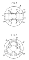
- the axial magnetic field can be generated even when the first high resistance areas 33, 34 are formed linear as in Fig. 5 instead of being circular arc-shaped. It is further preferable that, as shown in Fig. 6, the bridge conductor 50 is divided into three parts and the first high resistance areas are arranged to cross them, thereby increasing the area of generating the axial magnetic field. In this case, the electrodes facing each other are desired to be deviated by 60° from each other. It is further preferable that the bridge conductor is divided into more than three parts and the first high resistance areas are arranged to cross them.
- the high resistance areas in the electrodes described above can be formed by filling the groove 33 38, 43 48 with a high resistance material.
- Fig. 7 (a) is a side view showing an electrode structure of a vacuum interrupter in accordance with an embodiment of the present invention
- Fig. 7, (b) is a plan view in the direction of the arrow b-b
- Fig. 7 (c) is a plan view in the direction of the arrow c-c in fig. 7 (a).
- reference numerals 33, 34, 43, 44 denote grooves for the first high resistance areas in the same manner as in Fig.
- grooves do not pass through the contact surfaces of the electrodes 30, 40, and the grooves have a certain depth from the back sides of the electrodes 30, 40 towards the contact surfaces and are formed at a certain distance from the peripheral edges of the electrodes 30, 40.
- reference numerals 35 to 38, 45 to 48 denote the second high resistance areas, but they do not pass through from the contact surfaces of the electrodes 30, 40 toward the backs, and the grooves have a certain depth from the backs of the electrodes 30, 40 towards the contact surfaces.
- Numerals 59, 69 denote circular third high resistance areas formed inside the electrodes extending from the first high resistance areas 33, 34, 43, 44 towards the electrode peripheral edges and they are grooves in this embodiment. The arrangement of the grooves is also shown in Fig. 8.
- an arc A is formed between the electrodes 30, 40.
- This arc A is formed on all surfaces of the electrodes 30, 40 when the arc current is very large.
- the current i to passing from the conductive rod 5 towards the conductive rod 6 first passes from said conductive rod 5 being divided into two currents passing reversely to each other as shown in Fig. 7 (a), then passes reversely to each other as shown in Fig. 7 (a), then passes through the circular arc-shaped electrode parts 31, 32 by way of the projecting parts 52, 53 as shown in Fig.
- the current i coming from the contact surfaces passes through the current passages 55 and 56 being divided into two currents, then passes through the circular arc-shaped electrode parts 41, 42 in the reverse direction, and after passing through the projecting parts 61 and 62, reaches the conductive rod 6 by way of the bridge conductor 60.
- the axial magnetic fields generated by each loop are in reverse directions to one another as shown in Fig. 7 (b), (c) and the magnetic fields in the center part of the electrode axis are mutually offset.
- a residual magnetic flux affecting the extinction of ionized metals in the arc can be reduced.
- a strong axial magnetic field acts on almost all over the contact surfaces of the electrodes parallel to the arc, thereby the arc is stably and uniformly distributed.
- the high resistance areas 33 to 38, 43 to 48, 59, 69 are not exposed on the contact with the arc, local melting due to arc energy concentration can be effectively prevented.
- FIG. 8 (a), (b), A further embodiment of the present invention is shown in Fig. 8 (a), (b), wherein a thin electrode structure is attained by interposing a reinforcing member 57 between the bridge conductor 50 and the electrode 30, because electrode materials of high conductivity such as copper or silver used in general have disadvantages in view of mechanical strength and cost saving.
- An inside part 39 of the electrode 30 projects to prevent application of mechanical force to the outside parts 31, 32 of the electrode and arm parts of the bridge conductor 50 when performing opening and closing.
- a material, such as stainless steel, of less conductivity than the electrode material is preferably used as the reinforcing member 57. It is also satisfactory to form the inside part 39 of the electrode 30 of an electrode material resistant to welding and high pressure, while forming the outside parts 31, 32 of ordinary copper.
- the axial magnetic field can be generated even when the first high resistance areas 33, 34 are formed linear as in the embodiment of Fig. 9 instead of being circular arc-shaped.
- the bridge conductor 50 is divided into three parts and the first high resistance areas are arranged to cross them, thereby increasing the area of generating the axial magnetic field.
- the electrodes facing to each other are desired to be deviated by 60° from each other.
- the bridge conductor is divided into more than three parts and the first high resistance areas are arranged to cross them.
- the high resistance areas in the embodiments described above can be formed by impregnating a high resistance material in the groove 33 38, 43 48.
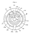
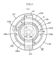
- Fig. 11 (a) is a side view showing an electrode structure of a vacuum interrupter in accordance with the present invention
- Fig. 11 (b) is a plan view in the direction of the arrow b-b in fig. 11 (a)
- Fig. 11 (c) is a plan view in the direction of the arrow c-c in Fig. 11 (a)
- Fig. 11 (d) is an explanatory sectional view showing one electrode in fig. 11 (a).
- reference numerals 103, 104, 123, 124 denote the first high resistance areas formed on each electrode 10, 20 facing one another, passing through from the facing surfaces to the back and keeping certain distances from the peripheral edges of the electrodes 10, 20, e.g., at about 20% of the diameter.
- the first high resistance areas are formed of grooves consisting of a pair of circular arc-shaped parts 103a, 104a, 123a, 124a arranged substantially symmetrical to the center of each electrode and not connected one another, and linear parts 103b, 103c, 104b, 104c, 123b, 123c, 124b, 124c extending from both ends of the circular arc towards the center of each electrode substantially perpendicular to the bridge conductors 50, 60 and not connected to one another.
- Numerals 107, 108 denote second high resistance areas provided inside the first high resistance areas 103, 104, 123, 124, and, as shown in Fig.
- these second high resistance areas pass through the electrodes 10, 20 connecting an annular high resistance area of which the outer diameter is D1 on the electrode back sides, to an annular high resistance area of which the outer diameter is D2 (where D1>D2) on the electrode facing sides.
- parallel annular parts 107a, 108a are formed on the electrode backs, while inclined annular parts 107b, 108b are formed on the electrode facing sides towards the center of the electrode in continuation to the parallel annular parts 107a, 108a.
- the second high resistance areas are actually formed of annular grooves coaxial with the first high resistance areas 103, 104, 123, 124.
- Numerals 113, 133 denote contacts each projecting in a form of a ring of which the inner diameter is D3, i.e. with central recesses 114, 134 of diameter D3.
- the electrodes 5, 6 are connected to the backs of the contacts 113, 134 by way of cylindrical conductive members 115, 135 with outer diameter D4 for electrical connection to the outside of the vacuum container. Since there is the relation of D3 > D4 between this outer diameter D4 of the conductive members 115, 135 and the inner diameter D3 of the contacts 113, 133, the contacts 113, 133 come in contact with each other outside the diameter D4.
- these contacts 113, 133 are made of an alloy of low melting point material such as bismuth and copper of which the mechanical strength is not high, and therefore in order to prevent the electrodes 10, 20 from deformation and breakage when they are opened and closed, reinforcing members 116, 136 of low conductivity and high mechanical strength as compared with copper, etc. are fixed to the back sides of the contacts 113, 133. Since the electrodes 10, 20 are disposed on the outer peripheries of the contacts 113, 133, the electrodes are insulated from the contacts 113, 133 with high insulation material as compared with the spacing portion or copper material forming the second high resistance areas 107, 108.
- Each electrode 10, 20 is partitioned by the first high resistance areas 103, 104, 123, 124 respectively.
- the bridge conductors 50, 60 are respectively arranged on the backs of the electrodes over the first high resistance areas 103, 104, 123, 124 so that the electrode outside parts 10, 20 and 131, 132 are electrically and mechanically connected to the conductive rods 5, 6.
- the electrodes 10, 20 are formed of an alloy of copper and chromium.
- the electrode 30 and the bridge conductor 50 are of the same configuration as the electrode 40 and the bridge conductor 50 respectively in this embodiment, but the electrode 40 and the bridge conductor 60 are so arranged as to face to the electrode 30 and the bridge conductor 50 respectively being deviated by 90° therefrom. This is because a magnetic field formed by the current passing through one electrode is in the same direction as a magnetic field formed by the current passing through the other electrode.
- the vacuum interrupter arranged as above described performs the following operation.
- the current passage is formed by the conductive rod 5, the conductive member 115, the contacts 113, 133, the conductive member 135 and the conductive rod 6 in that order.
- the outer diameter D4 of the conductive members 115, 135 and the inner diameter D3 of the contacts 113, 133 are in the relation D3 ⁇ D4, the current does not pass rectilinearly but is curved between the conductive members 115, 135 and the contacts 113, 133, thereby an arc formed after opening the electrodes being easily transferred.
- the current passes as indicated by the broken line in Fig. 11 (a) and an arc is formed between a point A of the contact 113 and a point A' of the contact 133. Since a force extending the arc from the surfaces of the contacts 113, 133 outward is applied to the arc, the arc is transferred across the second high resistance areas 107 to ignite between points B, B' on the surfaces of the electrodes 10, 20.
- the current i passes from the conductive rod 5 to the point B by way of the bridge conductor 50, projecting part 111, outside part 10 of the electrode and through between the linear parts 103c, 104c in the first high resistance areas.
- the current i further passes from the point B' to the bridge conductor 60 through between the linear parts 123b, 124b in the first high resistance areas and by way of the outside part 131 of the electrode and projecting part 141.
- each one turn is formed by the current loop 50 ⁇ 111 ⁇ 101 ⁇ B and B' ⁇ 131 ⁇ 141 ⁇ 60, and an axial magnetic field is generated.
- an arc is stably and uniformly distributed on the surfaces of the electrodes, enabling interruption of large currents thereby.
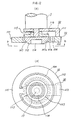
- Fig. 12 (a), (b) are a sectional view and a plan view in the direction of the arrow b-b of a portion near one electrode of a vacuum interrupter in accordance with a yet further embodiment, each first high resistance area is formed into one circular arc and the bridge conductor 50 is transformed according to such configuration of the first high resistance areas.
- the applied current does not pass through the electrode 10 and the bridge conductor 50 and Joule's heat is not generated, either, in this embodiment.
- the electrode 10 can be connected to the bridge conductor 50 at only one point in the projecting part 111.
- the current passing outside part of the first high resistance areas 104 is increased more, than the foregoing embodiment, and it is possible to generate a stronger axial magnetic field resulting in improvement of the interruption performance.
- Fig. 12 (a), (b) Although only one electrode 30 and one bridge conductor 50 are shown in Fig. 12 (a), (b), it is further possible to have a structure in which both or either of the facing electrodes and the bridge 2onductors is arranged as shown in Fig. 12 (a), (b).
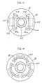
- the axial magnetic field can be generated even when the first high resistance areas 33, 34 are formed linear as in fig. 13 instead of being circular arc-shaped.
- the bridge conductor 50 is divided into three parts and the first high resistance areas are arranged to cross them, thereby increasing the area of generating the axial magnetic field.
- the electrodes facing each other are desired to be deviated by 60° from each other considering the direction of the magnetic field.
- the bridge conductor is divided into more than three parts and the first high resistance areas are arranged to cross them.
- the high resistance areas in the embodiments described above can be formed by filling the grooves with a high resistance material.
- it is satisfactory if the first high resistance areas have no linear parts perpendicular to the bridge conductors and extending towards the center of each electrode.
Landscapes
- High-Tension Arc-Extinguishing Switches Without Spraying Means (AREA)
Abstract
Description
- The present invention relates to a vacuum interrupter of high mechanical strength in which an arc is stably and uniformly distributed on surfaces of electrodes, and electro-magnetic repulsive force generated at the time of applying a large current is reduced.
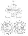
- Usually, as shown in Fig. 1, a vacuum interrupter comprises a vacuum container (1) closed with end plates (21), (22), a pair of electrodes (30), (40) facing to each other and conductive rods (5), (6) provided through said end plates (5), (6), and in which a bellows (7) is mounted on one electrode (6) to be movable in the axial direction without affecting air-tightness, and said electrodes (30), (40) are detachable and can be connected to each other. Further, a shield (8) is provided to acquire evaporated metals. Said conductive rod (6) is driven by a drive mechanism not shown for switching operation of an electric circuit.
- In such type of vacuum interrupter, it is well known that interruption performance can be improved by stably and uniformly distributing the arc on the surfaces of the electrodes by applying a magnetic field in parallel to the arc, particularly when interrupting a large current arc. It is also known that when said electrodes (30), (40) are in a closed state, an electro-magnetic repulsive force is generated due to the large current application, and a small gap is formed between said electrodes (30), (40), thereby generating a local arc which brings about welding or deteriorates the electrode surfaces, finally lowering withstand voltage performance.
- To meet the aforesaid interruption of large current arc and to reduce the electro-magnetic repulsive force when applying a large current, a further vacuum interrupter has been proposed as shown in Fig. 2(a)-(c) (Japanese laid-open Patent Publication (unexamined) No.57-3327). Fig. 2 (a) is a side view showing an example of arrangement of electrodes in such prior vacuum interrupter, Fig. 2 (b) is a plan view in the direction of the arrow b-b, and Fig. 2 (c) is a plan view in the direction of the arrow c-c. In these drawings, reference numerals (50), (60) designate bridge conductors respectively fixed on the ends of the bridge conductors (5), (6). These bridge conductors (5), (6) are rectangular and projecting parts (51), (52), (61), (62) are respectively formed on both ends thereof. Numerals (30), (40) disignate a pair of electrodes connected electrically to each bridge conductor (50), (60) on their outer peripheral back sides respectively. As shown in Fig.2 (b), (c), circular arc-shaped grooves (33), (34), (43), (44) serving as high resistance areas are formed on each electrode (30), (40) by cutting at required distances, thus circular arc-shaped electrode parts (31), (32) and (41), (42) serving as outside parts of the electrodes partitioned by these grooves (33), (34) and (43), (44) are formed. Said bridge conductor (50) is so arranged as to cross the grooves (43), (44), and the projecting parts (51), (52) and (61), (62) are electrically and mechanically connected to substantially central parts of said circular arc-shaped electrode parts (31), (32) and (41), (41).
- Gaps between said bridge conductors (50), (60) and the electrodes (30), (40) are desired to be as small as possible, but it is necessary that the gaps are in a range in which the electrodes (30), (40) do not come in contact with the bridge conductors (50), (60) when the electrodes are butted to each other bringing about elastic deformation due to a mechanical force applied. The aforesaid electrode (30) and the bridge conductor (50) are respectively of the same configuration as the electrode (40) and the bridge conductor (60), but the electrode (40) and the bridgre conductor (60) are so arranged as to face to the electrode (30) and the brdige conductor (50) by 90° respectively being deviated by 90° therefrom.
- According to this prior art, when an opening operation is performed by an operation mechanism not shown, an arc is formed between the electrodes (30), (40), and a current i passes from the conductive rod (5) toward the conductive rod (6). In this step, when an arc is formed between a point A of the electrode (30) and a point A' of the electrode (40), the current i passes from the conductive rod (5) to the arc point A by way of the bridge conductor (50), the projecting part (51) thereof, the circular arc part (31) of said electrode (30) and a gap B between the grooves (33), (34). That is, a substantial one turn is formed by a current loop (5) → (50) → (51) → (31) → B → A is formed. Since the (51) → (31) → B → A is a loop formed by the electrode itself, the loop is near the point A and a strong axial magnetic field is generated. In the same manner, the current i passes from the point A' of the other electrode (40) to the conductive rod (6) by way of a gap C between the grooves (43), (44) of the electrode (40), the circular arc-shaped electrode part (41), the projecting part (61) and the bridge conductor (60). That is, one turn is further formed by a current loop A' → C → (41) → (61) → (60) → (6) is further formed, and a magnetic field of the same axial direction as the foregoing loop is generated. Thus, a strong combined magnetic flux in the axial direction acts in parallel to the arc A-A' as indicated by the arrow φ in Fig. 2(a), effectively preventing emission and diffusion of ionized metals from the arc to outside, acquiring a sufficient amount of plasma particles and stabilizing the arc. In the event that an accidental large current should pass in the closed state, an electro-magnetic repulsive force is generated at the contact points due to concentration of the current and acts to separate the
electrodes part 51 to the tap B in theelectrode 30 is same as that from the gap C to the projectingpart 61 in theother electrode 40, the circular arc-shaped electrode parts electrodes shaped electrode parts - Thus, the electrode contact force applied to said
electrodes - According to the prior vacuum interrupter arranged as above, however, a serious problem exists in that, in the arc formed between the
electrodes grooves - DE-A-3416368 discloses a vacuum interrupter generally similar to that shown in figure 2 but additionally provided with rectilinear slots in the electrode extending radially inwards from the circular arc-shaped grooves serving as high resistance areas, in order to direct and concentrate the current flow path and enhance the magnetic field generated, while reducing eddy currents.
- The object of the invention is to provide electrode structures for vacuum interrupters, in which the interrupting performance is still further improved relative to the prior art.
- According to one aspect of the invention, there is provided a vacuum interrupter for opening and closing a current passage by a pair of electrodes which are incorporated in a vacuum container, connectable to and separable from each other and respectively mounted on conductive rods, wherein at least one of said pair of electrodes is provided with first high resistance areas formed passing through from a back side towards a contact surface thereof at specified distances from a peripheral edge of the electrode and facing each other, and second high resistance areas extending from ends of the first high resistance areas towards the centre of said electrode and not connected to each other, and wherein outside parts of the electrode between the first high resistance areas and said peripheral edge are electrically connected to said conductive rod on said back side of the electrode by way of a bridge conductor (50) arranged over the first high resistance areas, characterised by annular third high resistance areas (59) formed from the first high resistance areas inside the electrode to said peripheral edge of the electrode.
- According to another aspect of the invention there is provided a vacuum interrupter for opening and closing a current passage by a pair of electrodes which are incorporated in a vacuum container, connectable to and separable from each other and respectively mounted on conductive rods, wherein at least one of said pair of electrodes comprises at least one first high resistance area formed passing through from a facing surface to a back side thereof at specified distances from a peripheral edge of the electrode and facing each other, and a bridge conductor arranged over the first high resistance areas and electrically connecting outside parts of the electrode between the first high resistance areas and said peripheral edge to said conductive rod on said back side of the electrode, characterised by a second high resistance area formed inside the first high resistance area or areas of said electrode and passing through said electrode connecting an annular high resistance area of which the outer diameter is D₁ on the back side of the electrode to an annular high resistance area (107b) of which the outer diameter is D₂ in the facing sides of the electrode where D₁>D₂, a contact (113, 133) projecting in the form of a ring and of which the inner diameter is D₃, and a cylindrical conductive member connecting said contact to said conductive rod (5, 6) and of which the diameter is D₄ where D₃>D₄.
In the drawings: - Figure 1 is a sectional view showing a prior vacuum interrupter;
- Figure 2 shows an electrode structure of the prior vacuum interrupter, and wherein (a) is a side view; and (b), (c) are plan views;
- Figure 3 shows an electrode structure, wherein (a) is a side view; and (b), (c) are plan views;
- Figure 4 shows another electrode structure, wherein (a) is a sectional view; and (b) is a plan view
- Figures 5 and 6 are plan view respectively showing further electrode structures;
- Figure 7 shows an electrode structure of a vacuum interrupter in accordance with an embodiment of the present invention, and wherein (a) is a side view; and (b), (c) are plan views;
- Figure 8 shows a further embodiment of the invention, and wherein (a) is a sectional view; and (b) is a plan view;
- Figures 9 and 10 are plan views respectively showing further embodiments of the present invention;
- Figure 11 shows an electrode structure of in accordance with a further embodiment of the invention, and wherein (a), (d) are sectional views; and (b), (c) are plan views;
- Figure 12 shows a further embodiment of the present invention, and wherein (a) is a sectional view; and (b) is a plan view; and
- Figures 13 and 14 are plan views respectively showing further embodiments of the present invention.
- Figure 3 (a) is a side view showing an electrode structure of a vacuum interrupter, Fig. 3 (b) is a plan view in the direction of the arrow b-b in Figure 3, Figure 3 (b) is a plan view in the direction of the arrow b-b in Fig. 3 (a), and Fig. 3 (c) is a plan view in the direction of the arrow c-c in Fig. 3 (a).
- In the drawings,
reference numberals electrode electrode Numerals 35 to 38, 45 to 48 denote second high resistance areas extending from both ends of the firsthigh resistance areas electrode conductors electrode high resistance areas 33 to 38, 45 to 48, therebycurrent paths outside parts electrodes current path 53 to 56 is narrower than that of thebridge conductors bridge conductors high resistance areas outside parts conductive rods electrode 30 and thebridge conductor 50 are of the same configuration as theelectrode 40 and thebridge conductor 50 respectively, but theelectrode 40 and thebridge conductor 60 are so arranged as to face to theelectrode 30 and thebridge conductor 50 respectively being deviated by 90° therefrom. - When opening operation is performed by an operation mechanism (not shown), an arc is formed between the
electrodes conductive rod 5 towards theconductive rod 6 and the arc is formed between a point A of oneelectrode 30 and a point A' of theother electrode 40, the current i passes from theconductive rod 5 to the arc point A by way of thebridge conductor 50, the projectingpart 51, theoutside part 31 and thecurrent passage 53. That is, a complete one turn is formed by acurrent loop 50 → 51 → 31 → 53 → A, and wherein since the 51 → 31 → 53 → A is a loop formed by the electrode itself and situated near the arc point A, a strong axial magnetic field is generated. In the same manner, the current i passes from the other point A' of theelectrode 40 to theconductive rod 6 by way of thecurrent passage 55, theoutside part 41, the projectingpart 61 and thebridge conductor 60. That is, a complete one turn is formed by the current loop A' → 55 → 41 → 61 → 60 → 6 and the same axial magnetic field as the foregoing current loop is formed. Thus, a strong combined axial magnetic flux acts in parallel to the arc A-A' indicated by the arrow φ in Fig. 3 (a), emission and diffusion of ionized metals to outside are effectively prevented and the arc is stabilized by acquiring a sufficient amount of plasma particles. In this connection, there is the possibility that an eddy current is generated in theelectrodes high resistance areas 35 38, 45 48, the generation of the magnetic field in the reverse direction can be prevented without taking nay particular measure to cope with the eddy current. - Fig. 4 a, b shows a thin electrode structure attained by interposing a reinforcing
member 57 between thebridge conductor 50 and the electrode, considering that electrode materials of high conductivity such as copper, silver used in general have disadvantages in view of mechanical strength and cost saving. Aninside part 39 of theelectrode 30 slightly projects to prevent application of mechanical force to theoutside parts bridge conductor 50 when performing opening and closing. A material, such as stainless steel, of less conductivity than the electrode material is preferably used as the reinforcingmember 57. It is also satisfactory to form theinside part 39 of theelectrode 30 of an electrode material resistant to welding the high pressure, while forming theoutside parts - Although the inside part of the electrode projects and the reinforcing member is added in Fig. 4, either one of such arrangements can be employed without the other.
- Although only one
electrode 30 and onebridge conductor 50 are shown in Fig. 4(a), (b), it is possible to have a structure in which both or either of the facing electrodes and the bridge conductors is arranged as shown in Fig. 4 (a), (b). - Although the arrangement is applied to a pair of electrodes disposed in the
vacuum container 1 in the foregoing description, it is also possible to apply such arrangement to either one electrode. - The axial magnetic field can be generated even when the first
high resistance areas bridge conductor 50 is divided into three parts and the first high resistance areas are arranged to cross them, thereby increasing the area of generating the axial magnetic field. In this case, the electrodes facing each other are desired to be deviated by 60° from each other. It is further preferable that the bridge conductor is divided into more than three parts and the first high resistance areas are arranged to cross them. - The high resistance areas in the electrodes described above can be formed by filling the
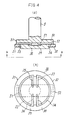
groove 33 38, 43 48 with a high resistance material. - Fig. 7 (a) is a side view showing an electrode structure of a vacuum interrupter in accordance with an embodiment of the present invention, Fig. 7, (b) is a plan view in the direction of the arrow b-b, and Fig. 7 (c) is a plan view in the direction of the arrow c-c in fig. 7 (a). In these drawings,
reference numerals electrodes electrodes electrodes reference numerals 35 to 38, 45 to 48 denote the second high resistance areas, but they do not pass through from the contact surfaces of theelectrodes electrodes Numerals high resistance areas - According to the vacuum interrupter of this embodiment described above, when an opening operation is performed by an operation mechanism (not shown) an arc A is formed between the
electrodes electrodes conductive rod 5 towards theconductive rod 6, first passes from saidconductive rod 5 being divided into two currents passing reversely to each other as shown in Fig. 7 (a), then passes reversely to each other as shown in Fig. 7 (a), then passes through the circular arc-shapedelectrode parts parts current paths high resistance areas electrode 30. That is, four pairs of one turns are formed by fourcurrent loops 50 → 51 → 31 → 53 → A, 50 → 51 → 31 → 54 → A, 50 → 52 → 32 → 53 → A and 50 → 52 → 32 → 53 → A. Since theloops 51 → A and 52 → A are formed by the electrode itself, these loops are near and a strong axial magnetic field is generated. - In the same manner, as shown in Fig. 7 (c), in the
other electrode 40, the current i coming from the contact surfaces passes through thecurrent passages electrode parts parts conductive rod 6 by way of thebridge conductor 60. That is, four pairs of one turns are formed by four current loops A → 55 → 41 → 61 → 60 → 6, A → 55 → 41 → 62 → 60 → 6, A → 56 → 42 → 61 → 60 → 6 and A → 56 → 42 → 62 → 60 → 6, and the axial magnetic field of the same direction as the preceding loops are further generated by each of them. - Furthermore, the axial magnetic fields generated by each loop are in reverse directions to one another as shown in Fig. 7 (b), (c) and the magnetic fields in the center part of the electrode axis are mutually offset. As a result, a residual magnetic flux affecting the extinction of ionized metals in the arc can be reduced. Accordingly, when a large current arc is formed, a strong axial magnetic field acts on almost all over the contact surfaces of the electrodes parallel to the arc, thereby the arc is stably and uniformly distributed. Moreover, since the
high resistance areas 33 to 38, 43 to 48, 59, 69 are not exposed on the contact with the arc, local melting due to arc energy concentration can be effectively prevented. - A further embodiment of the present invention is shown in Fig. 8 (a), (b), wherein a thin electrode structure is attained by interposing a reinforcing
member 57 between thebridge conductor 50 and theelectrode 30, because electrode materials of high conductivity such as copper or silver used in general have disadvantages in view of mechanical strength and cost saving. Aninside part 39 of theelectrode 30 projects to prevent application of mechanical force to theoutside parts bridge conductor 50 when performing opening and closing. A material, such as stainless steel, of less conductivity than the electrode material is preferably used as the reinforcingmember 57. It is also satisfactory to form theinside part 39 of theelectrode 30 of an electrode material resistant to welding and high pressure, while forming theoutside parts electrode 30 and onebridge conductor 50 are shown in Fig. 8 (a), (b), it is further satisfactory to have a structure in which both or either of the facing electrodes and the bridge conductors is arranged as shown in Fig. 4 (a), (b). - Although the arrangement in accordance with the present invention is applied to a pair of electrodes disposed in the
vacuum container 1 in the foregoing embodiment, it is also satisfactory to apply such arrangement to either one electrode. - The axial magnetic field can be generated even when the first
high resistance areas - It is further preferable that, as shown in Fig. 10, the
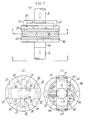
bridge conductor 50 is divided into three parts and the first high resistance areas are arranged to cross them, thereby increasing the area of generating the axial magnetic field. In this case, the electrodes facing to each other are desired to be deviated by 60° from each other. It is further preferable that the bridge conductor is divided into more than three parts and the first high resistance areas are arranged to cross them. The high resistance areas in the embodiments described above can be formed by impregnating a high resistance material in thegroove 33 38, 43 48. - Referring now to Fig. 11, a still further embodiment is described hereunder. Fig. 11 (a) is a side view showing an electrode structure of a vacuum interrupter in accordance with the present invention, Fig. 11 (b) is a plan view in the direction of the arrow b-b in fig. 11 (a), Fig. 11 (c) is a plan view in the direction of the arrow c-c in Fig. 11 (a) and Fig. 11 (d) is an explanatory sectional view showing one electrode in fig. 11 (a). In these drawings,
reference numerals electrode electrodes parts linear parts bridge conductors Numerals high resistance areas electrodes annular parts 107a, 108a are formed on the electrode backs, while inclinedannular parts 107b, 108b are formed on the electrode facing sides towards the center of the electrode in continuation to the parallelannular parts 107a, 108a. The second high resistance areas are actually formed of annular grooves coaxial with the firsthigh resistance areas Numerals central recesses electrodes contacts conductive members conductive members contacts contacts contacts electrodes members contacts electrodes contacts contacts high resistance areas electrode high resistance areas bridge conductors high resistance areas parts conductive rods electrodes - The
electrode 30 and thebridge conductor 50 are of the same configuration as theelectrode 40 and thebridge conductor 50 respectively in this embodiment, but theelectrode 40 and thebridge conductor 60 are so arranged as to face to theelectrode 30 and thebridge conductor 50 respectively being deviated by 90° therefrom. This is because a magnetic field formed by the current passing through one electrode is in the same direction as a magnetic field formed by the current passing through the other electrode. - The vacuum interrupter arranged as above described performs the following operation.
- Since only the
contacts conductive rod 5, theconductive member 115, thecontacts conductive member 135 and theconductive rod 6 in that order. In this step, the outer diameter D₄ of theconductive members contacts conductive members contacts electrodes bridge conductors contactors conductive members - When performing an opening operation, the current passes as indicated by the broken line in Fig. 11 (a) and an arc is formed between a point A of the
contact 113 and a point A' of thecontact 133. Since a force extending the arc from the surfaces of thecontacts high resistance areas 107 to ignite between points B, B' on the surfaces of theelectrodes high resistance areas contacts annular parts 107b, 108b are formed on the facing sides, the arc is easily transferred from between the points A-A' to between the points B-B'. When the arc is ignited between the points B-B' of theelectrodes conductive rod 5 to the point B by way of thebridge conductor 50, projectingpart 111, outsidepart 10 of the electrode and through between the linear parts 103c, 104c in the first high resistance areas. The current i further passes from the point B' to thebridge conductor 60 through between the linear parts 123b, 124b in the first high resistance areas and by way of theoutside part 131 of the electrode and projectingpart 141. - That is, each one turn is formed by the
current loop 50 → 111 → 101 → B and B' → 131 → 141 → 60, and an axial magnetic field is generated. As a result an arc is stably and uniformly distributed on the surfaces of the electrodes, enabling interruption of large currents thereby. - Fig. 12 (a), (b) are a sectional view and a plan view in the direction of the arrow b-b of a portion near one electrode of a vacuum interrupter in accordance with a yet further embodiment, each first high resistance area is formed into one circular arc and the
bridge conductor 50 is transformed according to such configuration of the first high resistance areas. The applied current does not pass through theelectrode 10 and thebridge conductor 50 and Joule's heat is not generated, either, in this embodiment. Accordingly theelectrode 10 can be connected to thebridge conductor 50 at only one point in the projectingpart 111. As a result, the current passing outside part of the firsthigh resistance areas 104 is increased more, than the foregoing embodiment, and it is possible to generate a stronger axial magnetic field resulting in improvement of the interruption performance. - Although only one
electrode 30 and onebridge conductor 50 are shown in Fig. 12 (a), (b), it is further possible to have a structure in which both or either of the facing electrodes and the bridge 2onductors is arranged as shown in Fig. 12 (a), (b). - Although the arrangement in accordance with the present invention is applied to a pair of electrodes disposed in the
vacuum container 1 in the foregoing embodiment, it is also possible to apply such arrangement to either one electrode. The axial magnetic field can be generated even when the firsthigh resistance areas - It is further preferable that, as shown in Fig. 14, the
bridge conductor 50 is divided into three parts and the first high resistance areas are arranged to cross them, thereby increasing the area of generating the axial magnetic field. In this case, the electrodes facing each other are desired to be deviated by 60° from each other considering the direction of the magnetic field. It is further preferable that the bridge conductor is divided into more than three parts and the first high resistance areas are arranged to cross them. The high resistance areas in the embodiments described above can be formed by filling the grooves with a high resistance material. In addition, it is satisfactory if the first high resistance areas have no linear parts perpendicular to the bridge conductors and extending towards the center of each electrode.
Claims (11)
- A vacuum interrupter for opening and closing a current passage by a pair of electrodes (10, 20) which are incorporated in a vacuum container, connectable to and separable from each other and respectively mounted on conductive rods, wherein at least one of said pair of electrodes is provided with first high resistance areas (33, 34) formed passing through from a back side towards a contact surface thereof at specified distances from a peripheral edge of the electrode and facing each other, and second high resistance areas (35-38) extending from ends of the first high resistance areas towards the centre of said electrode and not connected to each other, and wherein outside parts of the electrode between the first high resistance areas and said peripheral edge are electrically connected to said conductive rod on said back side of the electrode by way of a bridge conductor (50) arranged over the first high resistance areas, characterised by annular third high resistance areas (59) formed from the first high resistance areas inside the electrode to said peripheral edge of the electrode.
- The vacuum interrupter according to Claim 1, wherein the first high resistance areas are circular arc-shaped high resistance areas arranged substantially symmetrical to the center of the electrode and not connected to each other.
- The vacuum interrupter according to Claim 1 or 2, wherein the first, second and third high resistance areas are respectively hollow grooves.
- The vacuum interrupter according to claim 1, 2, or 3, wherein the inside and outside parts of the electrode are respectively formed of different electrode materials.
- The vacuum interrupter according to claim 1, 2, 3 or 4, wherein the second high resistance areas are so arranged as to come nearer than the width of the bridge conductor (50).
- A vacuum interrupter for opening and closing a current passage by a pair of electrodes (10, 20) which are incorporated in a vacuum container, connectable to and separable from each other and respectively mounted on conductive rods (5, 6), wherein at least one of said pair of electrodes comprises at least one first high resistance area (103, 104, 123, 124) formed passing through from a facing surface to a back side thereof at specified distances from a peripheral edge of the electrode and facing each other, and a bridge conductor (50) arranged over the first high resistance areas and electrically connecting outside parts of the electrode between the first high resistance areas and said peripheral edge to said conductive rod (5, 6) on said back side of the electrode, characterised by a second high resistance area (107, 108) formed inside the first high resistance area or areas of said electrode and passing through said electrode connecting an annular high resistance area (107a) of which the outer diameter is D₁ on the back side of the electrode to an annular high resistance area (107b) of which the outer diameter is D₂ in the facing sides of the electrode where D₁>D₂, a contact (113, 133) projecting in the form of a ring and of which the inner diameter is D₃, and a cylindrical conductive member connecting said contact to said conductive rod (5, 6) and of which the diameter is D₄ where D₃>D₄.
- The vacuum interrupter according to claim 6, wherein the first high resistance areas comprise circular arc-shaped parts with substantially the same diameters arranged about the center of the electrode at substantially equal distances and not connected to one another, and rectilinear parts extending from ends of said circular arc-shaped parts towards the centre of the electrode and not connected to one another.
- A vacuum interrupter according to claim 6 or 7, wherein the high resistance areas are hollow grooves.
- The vacuum interrupter according to any one of claims 1 to 8, wherein a reinforcing material (57, 116, 136) of lower conductivity than the material of the electrode is inserted between the bridge conductor and the electrode.
- The vacuum interrupter according to claim 9 in which the diameter of the reinforcing material is smaller than the width of the bridge.
- The vacuum interrupter according to any one of claims 1 to 10, wherein both of the pair of electrodes are formed with substantially the same configuration and the electrodes face each other with their angles deviated so that a magnetic field formed by a current passing through one electrode is in the same direction as the magnetic field formed by a current passing through the other electrode.
Applications Claiming Priority (6)
| Application Number | Priority Date | Filing Date | Title |
|---|---|---|---|
| JP253961/85 | 1985-11-12 | ||
| JP253962/85 | 1985-11-12 | ||
| JP25396285A JPH0670889B2 (en) | 1985-11-12 | 1985-11-12 | Vacuum and breaker |
| JP25396185A JPS62113328A (en) | 1985-11-12 | 1985-11-12 | Vacuum cutter |
| JP195966/86 | 1986-08-21 | ||
| JP19596686A JPH0693341B2 (en) | 1986-08-21 | 1986-08-21 | Vacuum and breaker |
Publications (2)
| Publication Number | Publication Date |
|---|---|
| EP0245513A1 EP0245513A1 (en) | 1987-11-19 |
| EP0245513B1 true EP0245513B1 (en) | 1993-09-29 |
Family
ID=27327173
Family Applications (1)
| Application Number | Title | Priority Date | Filing Date |
|---|---|---|---|
| EP86906924A Expired - Lifetime EP0245513B1 (en) | 1985-11-12 | 1986-11-12 | Vacuum interrupter |
Country Status (4)
| Country | Link |
|---|---|
| US (1) | US4855547A (en) |
| EP (1) | EP0245513B1 (en) |
| DE (1) | DE3689122T2 (en) |
| WO (1) | WO1987003136A1 (en) |
Families Citing this family (5)
| Publication number | Priority date | Publication date | Assignee | Title |
|---|---|---|---|---|
| US5387771A (en) * | 1993-04-08 | 1995-02-07 | Joslyn Hi-Voltage Corporation | Axial magnetic field high voltage vacuum interrupter |
| DE19534398A1 (en) * | 1995-09-16 | 1997-03-20 | Abb Patent Gmbh | Contact arrangement for a vacuum interrupter |
| DE19716278A1 (en) * | 1997-04-18 | 1998-10-22 | Abb Patent Gmbh | Vacuum switching device |
| DE19809305A1 (en) * | 1998-03-05 | 1999-09-09 | Abb Patent Gmbh | Contact part arrangement for vacuum chamber |
| CN107093535B (en) * | 2017-06-06 | 2020-02-11 | 西安交通大学 | High-rated-current longitudinal magnetic field vacuum arc-extinguishing chamber contact structure |
Family Cites Families (8)
| Publication number | Priority date | Publication date | Assignee | Title |
|---|---|---|---|---|
| US3327081A (en) * | 1964-11-25 | 1967-06-20 | Allis Chalmers Mfg Co | Contact with high resistance material insert |
| JPS58810B2 (en) * | 1976-12-06 | 1983-01-08 | 株式会社日立製作所 | Vacuum cutter |
| DE3173171D1 (en) * | 1980-12-22 | 1986-01-23 | Mitsubishi Electric Corp | Vacuum interrupter |
| JPS58100325A (en) * | 1981-12-09 | 1983-06-15 | 三菱電機株式会社 | Vacuum breaker |
| DE3401497A1 (en) * | 1982-07-22 | 1984-08-09 | Ernst Prof. Dr.techn.habil. 1000 Berlin Slamecka | Vacuum switch contact arrangement |
| DE3235298A1 (en) * | 1982-09-21 | 1984-03-22 | Siemens AG, 1000 Berlin und 8000 München | VACUUM SWITCH TUBES WITH RING PART AND DIAMETRAL BRIDGE OF SWITCHES |
| DE3416368C2 (en) * | 1984-04-30 | 1986-07-17 | Ernst Prof. Dr.techn.habil. 1000 Berlin Slamecka | Vacuum switch contact arrangement |
| JPS61195528A (en) * | 1985-02-22 | 1986-08-29 | 三菱電機株式会社 | Electrode structure of vacuum breaker |
-
1986
- 1986-11-12 US US07/069,555 patent/US4855547A/en not_active Expired - Fee Related
- 1986-11-12 DE DE86906924T patent/DE3689122T2/en not_active Expired - Fee Related
- 1986-11-12 WO PCT/JP1986/000576 patent/WO1987003136A1/en not_active Ceased
- 1986-11-12 EP EP86906924A patent/EP0245513B1/en not_active Expired - Lifetime
Also Published As
| Publication number | Publication date |
|---|---|
| DE3689122T2 (en) | 1994-05-05 |
| US4855547A (en) | 1989-08-08 |
| EP0245513A1 (en) | 1987-11-19 |
| WO1987003136A1 (en) | 1987-05-21 |
| DE3689122D1 (en) | 1993-11-04 |
Similar Documents
| Publication | Publication Date | Title |
|---|---|---|
| US3946179A (en) | Vacuum interrupter | |
| KR100295905B1 (en) | Electrode structure for vacuum interrupter | |
| CA1077547A (en) | Vacuum type circuit interrupter with a contact having integral axial magnetic field means | |
| US5438174A (en) | Vacuum interrupter with a radial magnetic field | |
| JP2002184273A (en) | Vacuum interrupter for vacuum circuit-breaker | |
| JPH027318A (en) | Vacuum interrupter | |
| JPS62103928A (en) | Vacuum circuit breaker | |
| US3764764A (en) | Vacuum circuit breaker | |
| US4553002A (en) | Axial magnetic field vacuum-type circuit interrupter | |
| KR920006060B1 (en) | Vacuum switch tube | |
| US3935406A (en) | Vacuum interrupter | |
| EP0245513B1 (en) | Vacuum interrupter | |
| EP0052371B1 (en) | Vacuum interrupter | |
| KR880002576B1 (en) | Vaccum breaker | |
| JPH0112355Y2 (en) | ||
| JP3577740B2 (en) | Vacuum valve | |
| JPH0670889B2 (en) | Vacuum and breaker | |
| JP3231595B2 (en) | Vacuum valve | |
| JPH03272530A (en) | Vacuum valve for vacuum circuit breaker | |
| JP3431487B2 (en) | Vacuum valve | |
| JPS6313633Y2 (en) | ||
| JPH0693341B2 (en) | Vacuum and breaker | |
| JPH11149855A (en) | Circuit breaker | |
| JPS6166324A (en) | Vacuum interrupter | |
| JPH10321092A (en) | Bias electrode of vacuum valve, vacuum valve using this bias electrode, and vacuum circuit breaker using this vacuum valve |
Legal Events
| Date | Code | Title | Description |
|---|---|---|---|
| PUAI | Public reference made under article 153(3) epc to a published international application that has entered the european phase |
Free format text: ORIGINAL CODE: 0009012 |
|
| 17P | Request for examination filed |
Effective date: 19870630 |
|
| AK | Designated contracting states |
Kind code of ref document: A1 Designated state(s): DE GB |
|
| 17Q | First examination report despatched |
Effective date: 19910313 |
|
| GRAA | (expected) grant |
Free format text: ORIGINAL CODE: 0009210 |
|
| AK | Designated contracting states |
Kind code of ref document: B1 Designated state(s): DE GB |
|
| REF | Corresponds to: |
Ref document number: 3689122 Country of ref document: DE Date of ref document: 19931104 |
|
| REG | Reference to a national code |
Ref country code: GB Ref legal event code: 727A |
|
| REG | Reference to a national code |
Ref country code: GB Ref legal event code: 727B |
|
| REG | Reference to a national code |
Ref country code: GB Ref legal event code: SP |
|
| PLBE | No opposition filed within time limit |
Free format text: ORIGINAL CODE: 0009261 |
|
| STAA | Information on the status of an ep patent application or granted ep patent |
Free format text: STATUS: NO OPPOSITION FILED WITHIN TIME LIMIT |
|
| 26N | No opposition filed | ||
| REG | Reference to a national code |
Ref country code: GB Ref legal event code: 746 Effective date: 19951026 |
|
| PGFP | Annual fee paid to national office [announced via postgrant information from national office to epo] |
Ref country code: GB Payment date: 19981113 Year of fee payment: 13 |
|
| PGFP | Annual fee paid to national office [announced via postgrant information from national office to epo] |
Ref country code: DE Payment date: 19981120 Year of fee payment: 13 |
|
| PG25 | Lapsed in a contracting state [announced via postgrant information from national office to epo] |
Ref country code: GB Free format text: LAPSE BECAUSE OF NON-PAYMENT OF DUE FEES Effective date: 19991112 |
|
| GBPC | Gb: european patent ceased through non-payment of renewal fee |
Effective date: 19991112 |
|
| PG25 | Lapsed in a contracting state [announced via postgrant information from national office to epo] |
Ref country code: DE Free format text: LAPSE BECAUSE OF NON-PAYMENT OF DUE FEES Effective date: 20000901 |