EP0245259B1 - A device in a frame plate for a plate heat exchanger - Google Patents
A device in a frame plate for a plate heat exchanger Download PDFInfo
- Publication number
- EP0245259B1 EP0245259B1 EP86900300A EP86900300A EP0245259B1 EP 0245259 B1 EP0245259 B1 EP 0245259B1 EP 86900300 A EP86900300 A EP 86900300A EP 86900300 A EP86900300 A EP 86900300A EP 0245259 B1 EP0245259 B1 EP 0245259B1
- Authority
- EP
- European Patent Office
- Prior art keywords
- frame plate
- tube
- spacing member
- port
- assembly according
- Prior art date
- Legal status (The legal status is an assumption and is not a legal conclusion. Google has not performed a legal analysis and makes no representation as to the accuracy of the status listed.)
- Expired
Links
- 239000000463 material Substances 0.000 claims description 14
- RTAQQCXQSZGOHL-UHFFFAOYSA-N Titanium Chemical compound [Ti] RTAQQCXQSZGOHL-UHFFFAOYSA-N 0.000 claims description 3
- 229910001220 stainless steel Inorganic materials 0.000 claims description 3
- 239000010935 stainless steel Substances 0.000 claims description 3
- 229910052719 titanium Inorganic materials 0.000 claims description 3
- 239000010936 titanium Substances 0.000 claims description 3
- 239000004033 plastic Substances 0.000 claims description 2
- 229920003023 plastic Polymers 0.000 claims description 2
- 239000005060 rubber Substances 0.000 claims description 2
- 238000003754 machining Methods 0.000 description 2
- 238000004519 manufacturing process Methods 0.000 description 2
- 238000003466 welding Methods 0.000 description 2
- 230000007797 corrosion Effects 0.000 description 1
- 238000005260 corrosion Methods 0.000 description 1
- 239000012467 final product Substances 0.000 description 1
- 238000003825 pressing Methods 0.000 description 1
Images
Classifications
-
- F—MECHANICAL ENGINEERING; LIGHTING; HEATING; WEAPONS; BLASTING
- F28—HEAT EXCHANGE IN GENERAL
- F28F—DETAILS OF HEAT-EXCHANGE AND HEAT-TRANSFER APPARATUS, OF GENERAL APPLICATION
- F28F3/00—Plate-like or laminated elements; Assemblies of plate-like or laminated elements
-
- Y—GENERAL TAGGING OF NEW TECHNOLOGICAL DEVELOPMENTS; GENERAL TAGGING OF CROSS-SECTIONAL TECHNOLOGIES SPANNING OVER SEVERAL SECTIONS OF THE IPC; TECHNICAL SUBJECTS COVERED BY FORMER USPC CROSS-REFERENCE ART COLLECTIONS [XRACs] AND DIGESTS
- Y10—TECHNICAL SUBJECTS COVERED BY FORMER USPC
- Y10S—TECHNICAL SUBJECTS COVERED BY FORMER USPC CROSS-REFERENCE ART COLLECTIONS [XRACs] AND DIGESTS
- Y10S165/00—Heat exchange
- Y10S165/355—Heat exchange having separate flow passage for two distinct fluids
- Y10S165/356—Plural plates forming a stack providing flow passages therein
Definitions
- a plate heat exchanger consists basically of a package of heat exchange plates held together between one fixed frame plate and one movable frame plate.
- the heat exchange plates have a number of ports aligned with each other to form inlet and outlet channels extending through the plate package for two heat exchanging media.
- the ports in each plate for instance four in number, are arranged in pairs with two at the top and two at the bottom of the plate.
- each pair of ports in the heat exchange plates there is a corresponding pair of ports provided in a frame plate.
- These latter ports are connected to two tubes for transfer of the heat exchanging media.
- the tubes are attached to the frame plate by means of annular flanges arranged at the tube ends.
- the tube flanges can either be welded directly on the tubes or loosely fitted around them in abutment against smaller stop flanges fixed to the tube ends.
- the tube connections are arranged such that the tube flanges are situated at different distances from the frame plate.
- the tube flanges can overlap each other radially without interference.
- the known arrangement utilises a joint pipe, which has an annular flange at one end adapted to be connected to a tube flange, and which is fixed at its other end, for instance by welding, to the frame plate.
- the joint pipe and its flange must be made of an expensive, stainless material, usually stainless steel or titanium.
- the joint pipe must be able to resist strains caused by the heat exchanging medium and the connected pipe, so the wall of the joint pipe must be made comparatively thick.
- the joint pipe should have such a length that there is room to allow tools to be inserted between the flange of the joint pipe and the outer side of the frame plate.
- the said further flange must also have significant thickness for reasons of strength.
- an annular recess must be milled around the port on the inner side of the frame plate to accommodate the further flange.
- a further drawback is that in many countries the known arrangement must be approved by the authorities responsible for existing pressure vessel regulations.
- the present invention seeks to improve upon the above-mentioned known arrangement by providing an alternative which is simple and inexpensive.
- a frame plate assembly in or for a plate heat exchanger, comprising a frame plate with a pair of ports, lined with stainless material, and two tubes, provided with annular flanges and intended for heat exchanging media, connected with the frame plate such that the interior of each tube is in communication with a respective port in the frame plate, the distance between the centres of the ports, seen in the plane of the outer face of the frame plate, being smaller than the sum of the outer radii of the tube flanges and, therefore, the tube flanges being at different distances from the frame plate, characterised in that at least one port there is provided between the frame plate and the annular tube flange at least one removable spacing member surrounding a channel communicating the port and the interior of the tube, and said tube flange is connected with the frame plate by means separate from the spacing member and in a manner such that the spacing member is clamped between the frame plate and the tube flange.
- the ports of the frame plate are lined with linings of stainless material, for instance rubber, plastics stainless steel or titanium, arranged in the ports to protect the frame plate against aggressive media.
- the lining preferably extends through the spacing member also.
- the spacing member can be in a fixed position by means of flanges formed at the respective ends of the lining. Then one of the lining flanges abuts the inner face of the frame plate, while the other lining flange is arranged between the spacing member and the tube flange.
- the spacing member will not come into contact with the heat exchanging medium, and therefore, it may be made of an inexpensive non-stainless material.
- the lining is only required to give protection against aggressive media, it can be given a small wall thickness, for instance 1 mm. This avoids the need for an annular groove on the inner face of the frame plate to receive the lining flange.
- a small wall thickness for the lining also means that its flanges may be produced in a simple way by flaring out the ends of the lining by pressing.
- the latter may be allowed to have openings in the circumferential portion extending around the channel communicating between the port and the interior of the connected tube.
- the spacing member may consist of several separate parts.
- An assembly according to the invention does not require approval under existing pressure vessel regulations.
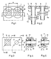
- the known arrangement shown in Figures 1 and 2 comprises a frame plate 1 with two ports having a distance D between their centres, seen in the plane of the outer face of the frame plate.
- the distance D is smaller than the sum of the outer radii of two flanges supported by two tubes which are connected to the ports.
- Two joint pipes, 2, 3, one 2 of which is longer than the other 3 are inserted into the ports such that they protrude to different distances from the outer side of the frame plate 1.
- the flanges 4, 5 of the joint pipes are provided with holes 10 intended for members connecting said flanges with the tube flanges 4a, 5a.
- the joint pipes 2, 3 and their flanges 4-7 are made of a stainless material, whereas the frame plate, which does not come into contact with any aggressive medium, is made of an inexpensive, non-corrosion-resistant material.
- Figure 3 shows the outer face of a frame plate 11 of a non-stainless material, which may constitute the fixed or the movable frame plate of a plate heat exchanger.
- Two ports 12,13 in the frame plate are situated so close to each other that tube flanges 16,17 of two connecting tubes (Figures 4 and 5) will not have room to be located beside each other at the same distance from the frame plate (compare Figures 1 and 2).
- a removable spacing member 14 with an annular cross-section, forming a communication channel between the port 12 and the interior of a tube to be connected with the frame plate.
- the frame plate 11 Around each port, and radially outside the spacing member 14, the frame plate 11 has threaded holes 15.
- the tube flanges 16, 17 are connected with the frame plate 11 by means of screw threaded studs 18,19 which extend through holes 20 in the tube flanges 16,17 and are fixed in the holes 15 in the frame plate. Nuts, not shown in the drawing, are arranged on end portions of the studs 18, 19 protruding from the holes of the tube flanges.
- linings 21, 22 of stainless material.
- the lining is provided with an annular flange 23, which is fixed between the spacing member 14 and the tube flange 16.
- the lining 21 is provided with a further annular flange 24, which abuts the inner side of the frame plate 11.
- the other port 13 ( Figure 5) has no spacing member and has, therefore, a lining 22 of a length corresponding to the thickness of the frame plate 11. Also the lining 22 is provided with annular flanges at the ends, one flange 25 being arranged between the frame plate 11 and the tube flange 17, and the other flange 26 abutting the inner face of the frame plate.
- the spacing member 14 will not be in contact with the aggressive medium because of the lining and it may, therefore, be made of an inexpensive non-stainless material, preferably the same material as the frame plate 11.
- spacing members may be arranged at both of the ports, having different lengths in the direction perpendicular to the outer face of the frame plate.
- the means for connecting the tube flanges to the frame plate may be constituted by screw bolts with heads having the same function as the nuts used with the previously described stud screws.
Landscapes
- Engineering & Computer Science (AREA)
- Physics & Mathematics (AREA)
- Thermal Sciences (AREA)
- Mechanical Engineering (AREA)
- General Engineering & Computer Science (AREA)
- Heat-Exchange Devices With Radiators And Conduit Assemblies (AREA)
Abstract
Description
- This invention relates to plate heat exchangers. A plate heat exchanger consists basically of a package of heat exchange plates held together between one fixed frame plate and one movable frame plate. The heat exchange plates have a number of ports aligned with each other to form inlet and outlet channels extending through the plate package for two heat exchanging media. Usually the ports in each plate, for instance four in number, are arranged in pairs with two at the top and two at the bottom of the plate.
- For each pair of ports in the heat exchange plates, there is a corresponding pair of ports provided in a frame plate. These latter ports are connected to two tubes for transfer of the heat exchanging media. The tubes are attached to the frame plate by means of annular flanges arranged at the tube ends. The tube flanges can either be welded directly on the tubes or loosely fitted around them in abutment against smaller stop flanges fixed to the tube ends.
- It has proved that with certain small heat exchanges, having a width of only a few decimetres, there has been a problem because the ports in the frame plate are situated so close to each other, that there is no room for a side by side arrangement of the tube flanges of the connecting tubes.
- In a known arrangement (see Figures 1 and 2), which solves the above-mentioned problem, the tube connections are arranged such that the tube flanges are situated at different distances from the frame plate. Hereby, the tube flanges can overlap each other radially without interference. The known arrangement utilises a joint pipe, which has an annular flange at one end adapted to be connected to a tube flange, and which is fixed at its other end, for instance by welding, to the frame plate.
- Although this known arrangement seems to solve in a simple way the above-described problem it does have certain drawbacks which make it expensive to produce. One drawback is that the consumption of expensive material is large. Since the heat exchangers concerned are mainly intended for aggressive media, the joint pipe and its flange must be made of an expensive, stainless material, usually stainless steel or titanium. Also, the joint pipe must be able to resist strains caused by the heat exchanging medium and the connected pipe, so the wall of the joint pipe must be made comparatively thick. In addition, the joint pipe should have such a length that there is room to allow tools to be inserted between the flange of the joint pipe and the outer side of the frame plate.
- Another drawback of the known arrangement is that the number of machining operations required during production also make it expensive. Thus, said annular flange is welded to the joint pipe. The frame plate has a considerable thickness, because it must be able to resist pressure from the compressed heat exchange package without bulging, so far cost reasons the frame plate is made of an inexpensive material, and in order that the frame plate within the port will be protected against aggressive media, the stainless joint pipe needs to be arranged such that it extends through the port to the inner side of the frame plate. The joint pipe must be fixed within the port and, therefore, needs a further flange welded at the end. The further flange is in turn welded to the inner side of the frame plate.
- The said further flange must also have significant thickness for reasons of strength. In order to avoid problems due to deflection of the heat exchange plate located nearest to the frame plate, an annular recess must be milled around the port on the inner side of the frame plate to accommodate the further flange.
- A further drawback is that in many countries the known arrangement must be approved by the authorities responsible for existing pressure vessel regulations.
- To sum up, the known arrangement involves a large consumption of expensive material and a lot for machining in its production which means an expensive final product.
- The present invention seeks to improve upon the above-mentioned known arrangement by providing an alternative which is simple and inexpensive.
- Reference is made to US-A-1948380 which discloses a heat transfer apparatus including a large number of parallel tubes which, at their ends, projectthrough tube sheets, the projection of adjacent tubes being different so that ferrules, connecting the tube ends to a J-bend providing a communication channel between them, are at different distances from the tube sheet to allow the tubes to be closer together.
- In accordance with the present invention there is provided a frame plate assembly in or for a plate heat exchanger, comprising a frame plate with a pair of ports, lined with stainless material, and two tubes, provided with annular flanges and intended for heat exchanging media, connected with the frame plate such that the interior of each tube is in communication with a respective port in the frame plate, the distance between the centres of the ports, seen in the plane of the outer face of the frame plate, being smaller than the sum of the outer radii of the tube flanges and, therefore, the tube flanges being at different distances from the frame plate, characterised in that at least one port there is provided between the frame plate and the annular tube flange at least one removable spacing member surrounding a channel communicating the port and the interior of the tube, and said tube flange is connected with the frame plate by means separate from the spacing member and in a manner such that the spacing member is clamped between the frame plate and the tube flange.
- The ports of the frame plate are lined with linings of stainless material, for instance rubber, plastics stainless steel or titanium, arranged in the ports to protect the frame plate against aggressive media. At a port provided with a spacing member according to the invention, the lining preferably extends through the spacing member also. The spacing member can be in a fixed position by means of flanges formed at the respective ends of the lining. Then one of the lining flanges abuts the inner face of the frame plate, while the other lining flange is arranged between the spacing member and the tube flange. Hereby, the spacing member will not come into contact with the heat exchanging medium, and therefore, it may be made of an inexpensive non-stainless material.
- Since the lining is only required to give protection against aggressive media, it can be given a small wall thickness, for instance 1 mm. This avoids the need for an annular groove on the inner face of the frame plate to receive the lining flange.
- A small wall thickness for the lining also means that its flanges may be produced in a simple way by flaring out the ends of the lining by pressing.
- In a plate heat exchanger having a lining extending through a port and related spacing member, the latter may be allowed to have openings in the circumferential portion extending around the channel communicating between the port and the interior of the connected tube. In addition, within the scope of the invention, the spacing member may consist of several separate parts.
- An assembly according to the invention does not require approval under existing pressure vessel regulations.
- The invention is explained in more detail in the following description which is given with reference to the accompagny drawing, in which:
- Figure 1 shows a previously known arrangement as mentioned in the foregoing;
- Figure 2 shows a cross-section taken along the line 11-11 in Figure 1 with connected tube flanges;
- Figure 3 shows a frame plate provided with a spacing member according to the invention, and
- Figures 4 and 5 show cross-sections taken along the lines IV-IV and V-V respectfully, of Figure 3, and including tube flanges and linings connected with the frame plate.
- The known arrangement shown in Figures 1 and 2 comprises a frame plate 1 with two ports having a distance D between their centres, seen in the plane of the outer face of the frame plate. The distance D is smaller than the sum of the outer radii of two flanges supported by two tubes which are connected to the ports. Two joint pipes, 2, 3, one 2 of which is longer than the other 3, are inserted into the ports such that they protrude to different distances from the outer side of the frame plate 1. On the protruding end portions of the
joint pipes annular flanges 4, 5, which are connected with correspondingly formedannular flanges flanges 4, 5 of the joint pipes are provided with holes 10 intended for members connecting said flanges with thetube flanges joint pipes annular flanges annular recesses joint pipes - I Figures 3,4 and 5, there is shown an embodiment according to the invention.
- Figure 3 shows the outer face of a
frame plate 11 of a non-stainless material, which may constitute the fixed or the movable frame plate of a plate heat exchanger. Twoports tube flanges left port 12 in Figure 3, there is shown aremovable spacing member 14 with an annular cross-section, forming a communication channel between theport 12 and the interior of a tube to be connected with the frame plate. Around each port, and radially outside thespacing member 14, theframe plate 11 has threadedholes 15. - As can be seen from Figures 4 and 5, the
tube flanges frame plate 11 by means of screw threadedstuds holes 20 in thetube flanges holes 15 in the frame plate. Nuts, not shown in the drawing, are arranged on end portions of thestuds ports linings port 12 where thespacing member 14 is arranged (Figure 4) thelining 21 extends through the latter. The lining is provided with anannular flange 23, which is fixed between thespacing member 14 and thetube flange 16. Thelining 21 is provided with a furtherannular flange 24, which abuts the inner side of theframe plate 11. - The other port 13 (Figure 5) has no spacing member and has, therefore, a
lining 22 of a length corresponding to the thickness of theframe plate 11. Also the lining 22 is provided with annular flanges at the ends, oneflange 25 being arranged between theframe plate 11 and thetube flange 17, and theother flange 26 abutting the inner face of the frame plate. - The spacing
member 14 will not be in contact with the aggressive medium because of the lining and it may, therefore, be made of an inexpensive non-stainless material, preferably the same material as theframe plate 11. - Embodiments other than the one shown in the drawing are conceivable within the scope of the invention. Thus, spacing members may be arranged at both of the ports, having different lengths in the direction perpendicular to the outer face of the frame plate. Further, the means for connecting the tube flanges to the frame plate may be constituted by screw bolts with heads having the same function as the nuts used with the previously described stud screws.
Claims (10)
Applications Claiming Priority (2)
| Application Number | Priority Date | Filing Date | Title |
|---|---|---|---|
| SE8500016 | 1985-01-03 | ||
| SE8500016A SE8500016D0 (en) | 1985-01-03 | 1985-01-03 | DEVICE ON A STANDARD PLATE FOR A PLATE HEAT EXCHANGER |
Publications (2)
| Publication Number | Publication Date |
|---|---|
| EP0245259A1 EP0245259A1 (en) | 1987-11-19 |
| EP0245259B1 true EP0245259B1 (en) | 1989-05-24 |
Family
ID=20358669
Family Applications (1)
| Application Number | Title | Priority Date | Filing Date |
|---|---|---|---|
| EP86900300A Expired EP0245259B1 (en) | 1985-01-03 | 1985-11-26 | A device in a frame plate for a plate heat exchanger |
Country Status (7)
| Country | Link |
|---|---|
| US (1) | US4750555A (en) |
| EP (1) | EP0245259B1 (en) |
| JP (1) | JPH0650237B2 (en) |
| DE (1) | DE3570517D1 (en) |
| DK (1) | DK161041C (en) |
| SE (1) | SE8500016D0 (en) |
| WO (1) | WO1986004134A1 (en) |
Families Citing this family (4)
| Publication number | Priority date | Publication date | Assignee | Title |
|---|---|---|---|---|
| SE502796C2 (en) * | 1994-05-18 | 1996-01-15 | Tetra Laval Holdings & Finance | Flat heat exchanger with lined connection pipes |
| SE507800C2 (en) * | 1996-11-14 | 1998-07-13 | Alfa Laval Ab | Plate heat exchanger with lined connection pipe and support device for counteracting deflection of the plate heat exterior heat transfer plate |
| SE518971C2 (en) * | 2001-04-24 | 2002-12-10 | Alfa Laval Ab | Feeding device for a plate heat exchanger, plate heat exchanger and method for manufacturing such a |
| RU2745175C1 (en) * | 2019-10-25 | 2021-03-22 | Данфосс А/С | Heat exchanger liner |
Family Cites Families (21)
| Publication number | Priority date | Publication date | Assignee | Title |
|---|---|---|---|---|
| US1651875A (en) * | 1926-07-17 | 1927-12-06 | Bell & Gossett Co | Unestricted-return water heater |
| US1948380A (en) * | 1931-11-30 | 1934-02-20 | Alco Products Inc | Header construction and heat transfer apparatus |
| US1969766A (en) * | 1932-06-11 | 1934-08-14 | Heat Exchanger Company | Heat exchange device |
| US2012269A (en) * | 1932-11-29 | 1935-08-27 | American Radlator & Standard S | Fin tube structure |
| US1966133A (en) * | 1933-03-30 | 1934-07-10 | Chester R Pieper | Heating device |
| US2374574A (en) * | 1943-10-05 | 1945-04-24 | Haveg Corp | Pipe flange |
| FR1228182A (en) * | 1958-03-05 | 1960-08-26 | Superheater Co Ltd | Improvements to tubular heat exchangers |
| GB1041805A (en) | 1964-07-13 | 1966-09-07 | Apv Co Ltd | Improvements in or relating to plate heat exchanger connections |
| US3393731A (en) * | 1967-05-12 | 1968-07-23 | Trane Co | Pressure vessel |
| DE2007033C3 (en) * | 1970-02-17 | 1979-06-21 | Hoechst Ag, 6000 Frankfurt | Plate heat exchanger made of polytetrafluoroethylene |
| DE2357059C3 (en) * | 1973-11-15 | 1979-05-17 | Eduard Ahlborn Gmbh, 3200 Hildesheim | Sealing for a plate heat exchanger |
| US3944264A (en) * | 1975-01-06 | 1976-03-16 | Westinghouse Air Brake Company | Pipe bracket |
| FR2334076A1 (en) * | 1975-12-05 | 1977-07-01 | Sera Husson Etu Realisa Aerody | AIR-TO-AIR OR AIR-TO-WATER HEAT EXCHANGER WITH LONG SERVICE LIFE AND CONSTANT EFFICIENCY, CONSTRUCTED FROM MODULAR ELEMENTS |
| SE402485B (en) * | 1976-10-29 | 1978-07-03 | Alfa Laval Ab | PLATE HEAT EXCHANGER |
| US4140172A (en) * | 1976-12-23 | 1979-02-20 | Fansteel Inc. | Liners and tube supports for industrial and chemical process equipment |
| GB2000267A (en) * | 1977-04-19 | 1979-01-04 | Apv Co Ltd | Immprovements in or relating to connecting ports for plate heat exchangers |
| US4142742A (en) * | 1977-09-15 | 1979-03-06 | Cornett Gerald W | Swivel fitting for flexible conduits |
| DE2840522A1 (en) * | 1977-10-05 | 1979-04-19 | Alfa Laval Ab | PLATE HEAT EXCHANGER |
| CH630718A5 (en) * | 1978-02-13 | 1982-06-30 | Agresto Ag International Sa | TUBE BUNDLE HEAT EXCHANGER. |
| FR2462214A1 (en) * | 1979-07-26 | 1981-02-13 | Ferodo Sa | PROCESS FOR CONFORMING A TUBE, ESPECIALLY FOR A HEAT EXCHANGER |
| US4630673A (en) * | 1982-06-21 | 1986-12-23 | Belleli S.P.A. | Clamping assembly heat exchanger tube plates |
-
1985
- 1985-01-03 SE SE8500016A patent/SE8500016D0/en unknown
- 1985-11-26 EP EP86900300A patent/EP0245259B1/en not_active Expired
- 1985-11-26 US US06/897,757 patent/US4750555A/en not_active Expired - Lifetime
- 1985-11-26 JP JP61500422A patent/JPH0650237B2/en not_active Expired - Lifetime
- 1985-11-26 DE DE8686900300T patent/DE3570517D1/en not_active Expired
- 1985-11-26 WO PCT/SE1985/000484 patent/WO1986004134A1/en not_active Ceased
-
1986
- 1986-09-02 DK DK416886A patent/DK161041C/en not_active IP Right Cessation
Also Published As
| Publication number | Publication date |
|---|---|
| EP0245259A1 (en) | 1987-11-19 |
| WO1986004134A1 (en) | 1986-07-17 |
| DK416886A (en) | 1986-09-02 |
| JPS63500958A (en) | 1988-04-07 |
| JPH0650237B2 (en) | 1994-06-29 |
| SE8500016D0 (en) | 1985-01-03 |
| DE3570517D1 (en) | 1989-06-29 |
| DK161041C (en) | 1991-10-28 |
| DK161041B (en) | 1991-05-21 |
| DK416886D0 (en) | 1986-09-02 |
| US4750555A (en) | 1988-06-14 |
Similar Documents
| Publication | Publication Date | Title |
|---|---|---|
| EP2672215B1 (en) | Plate heat exchanger | |
| CN100541100C (en) | Heat exchanger with reinforcing means | |
| CA1117101A (en) | Heat exchanger | |
| US4750555A (en) | Device in a frame plate for a plate heat exchanger | |
| KR20110083751A (en) | heat transmitter | |
| US7896064B2 (en) | Plate-type heat exchanger | |
| EP0169843B2 (en) | Frame plate and/or pressure plate for a plate heat exchanger | |
| US20140090804A1 (en) | Heat Exchanger | |
| EP0760082B1 (en) | Plate heat exchanger | |
| WO2003004955A1 (en) | Unitary body quadrilateral header for heat exchanger | |
| EP0119230B1 (en) | Plate heat exchanger | |
| US2046481A (en) | Heat exchanger | |
| US4846262A (en) | Head closure apparatus for heat exchanger | |
| AU3543099A (en) | Heat exchanger installation | |
| EP0247043B1 (en) | Lining for inlet- and outlet ports of a plate heat exchanger | |
| CN213120203U (en) | Heat exchanger tube box structure and heat exchanger | |
| JP3044894U (en) | Shell-tube heat exchanger | |
| CN220398311U (en) | Tube type heat exchanger | |
| EP3821192A1 (en) | Plate heat exchanger with reinforced covers and method for the production of said reinforced covers and their assembly | |
| JP2979501B2 (en) | Plate heat exchanger | |
| WO2018103986A1 (en) | Lining device and heat exchanger | |
| JP2747547B2 (en) | Plate heat exchanger | |
| JPH0334000B2 (en) | ||
| WO2024237885A1 (en) | A rotating/balancing apparatus with a hydraulic press for installing shell and tube heat exchangers | |
| JPS60128389A (en) | Reactor pressure vessel passage structure |
Legal Events
| Date | Code | Title | Description |
|---|---|---|---|
| PUAI | Public reference made under article 153(3) epc to a published international application that has entered the european phase |
Free format text: ORIGINAL CODE: 0009012 |
|
| 17P | Request for examination filed |
Effective date: 19870623 |
|
| AK | Designated contracting states |
Kind code of ref document: A1 Designated state(s): DE FR GB IT SE |
|
| 17Q | First examination report despatched |
Effective date: 19880122 |
|
| GRAA | (expected) grant |
Free format text: ORIGINAL CODE: 0009210 |
|
| AK | Designated contracting states |
Kind code of ref document: B1 Designated state(s): DE FR GB IT SE |
|
| ITF | It: translation for a ep patent filed | ||
| REF | Corresponds to: |
Ref document number: 3570517 Country of ref document: DE Date of ref document: 19890629 |
|
| ET | Fr: translation filed | ||
| PLBE | No opposition filed within time limit |
Free format text: ORIGINAL CODE: 0009261 |
|
| STAA | Information on the status of an ep patent application or granted ep patent |
Free format text: STATUS: NO OPPOSITION FILED WITHIN TIME LIMIT |
|
| 26N | No opposition filed | ||
| ITTA | It: last paid annual fee | ||
| EAL | Se: european patent in force in sweden |
Ref document number: 86900300.4 |
|
| REG | Reference to a national code |
Ref country code: GB Ref legal event code: IF02 |
|
| PGFP | Annual fee paid to national office [announced via postgrant information from national office to epo] |
Ref country code: SE Payment date: 20041105 Year of fee payment: 20 |
|
| PGFP | Annual fee paid to national office [announced via postgrant information from national office to epo] |
Ref country code: FR Payment date: 20041109 Year of fee payment: 20 |
|
| PGFP | Annual fee paid to national office [announced via postgrant information from national office to epo] |
Ref country code: DE Payment date: 20041118 Year of fee payment: 20 |
|
| PGFP | Annual fee paid to national office [announced via postgrant information from national office to epo] |
Ref country code: GB Payment date: 20041124 Year of fee payment: 20 |
|
| PG25 | Lapsed in a contracting state [announced via postgrant information from national office to epo] |
Ref country code: GB Free format text: LAPSE BECAUSE OF EXPIRATION OF PROTECTION Effective date: 20051125 |
|
| REG | Reference to a national code |
Ref country code: GB Ref legal event code: PE20 |
|
| EUG | Se: european patent has lapsed |