EP0245215B1 - Vorrichtung zum Reinigen von Metall- und Nichtmetallteilen, wie kleinen Gegenständen und mechanischen Bestandteilen - Google Patents
Vorrichtung zum Reinigen von Metall- und Nichtmetallteilen, wie kleinen Gegenständen und mechanischen Bestandteilen Download PDFInfo
- Publication number
- EP0245215B1 EP0245215B1 EP87830135A EP87830135A EP0245215B1 EP 0245215 B1 EP0245215 B1 EP 0245215B1 EP 87830135 A EP87830135 A EP 87830135A EP 87830135 A EP87830135 A EP 87830135A EP 0245215 B1 EP0245215 B1 EP 0245215B1
- Authority
- EP
- European Patent Office
- Prior art keywords
- axis
- tank
- metal
- rotating element
- machine
- Prior art date
- Legal status (The legal status is an assumption and is not a legal conclusion. Google has not performed a legal analysis and makes no representation as to the accuracy of the status listed.)
- Expired
Links
- 239000002184 metal Substances 0.000 title claims description 17
- 229910052755 nonmetal Inorganic materials 0.000 title claims description 12
- 238000005406 washing Methods 0.000 claims description 33
- 230000003014 reinforcing effect Effects 0.000 claims description 2
- 238000007599 discharging Methods 0.000 claims 1
- 239000002904 solvent Substances 0.000 description 10
- 230000000875 corresponding effect Effects 0.000 description 5
- 238000004519 manufacturing process Methods 0.000 description 2
- 230000004048 modification Effects 0.000 description 2
- 238000012986 modification Methods 0.000 description 2
- 230000001419 dependent effect Effects 0.000 description 1
- 230000001627 detrimental effect Effects 0.000 description 1
- 238000001035 drying Methods 0.000 description 1
- 230000000694 effects Effects 0.000 description 1
- 238000007602 hot air drying Methods 0.000 description 1
- 238000007654 immersion Methods 0.000 description 1
- 238000011084 recovery Methods 0.000 description 1
Images
Classifications
-
- B—PERFORMING OPERATIONS; TRANSPORTING
- B08—CLEANING
- B08B—CLEANING IN GENERAL; PREVENTION OF FOULING IN GENERAL
- B08B3/00—Cleaning by methods involving the use or presence of liquid or steam
- B08B3/04—Cleaning involving contact with liquid
- B08B3/045—Cleaning involving contact with liquid using perforated containers, e.g. baskets, or racks immersed and agitated in a liquid bath
-
- C—CHEMISTRY; METALLURGY
- C23—COATING METALLIC MATERIAL; COATING MATERIAL WITH METALLIC MATERIAL; CHEMICAL SURFACE TREATMENT; DIFFUSION TREATMENT OF METALLIC MATERIAL; COATING BY VACUUM EVAPORATION, BY SPUTTERING, BY ION IMPLANTATION OR BY CHEMICAL VAPOUR DEPOSITION, IN GENERAL; INHIBITING CORROSION OF METALLIC MATERIAL OR INCRUSTATION IN GENERAL
- C23G—CLEANING OR DE-GREASING OF METALLIC MATERIAL BY CHEMICAL METHODS OTHER THAN ELECTROLYSIS
- C23G5/00—Cleaning or de-greasing metallic material by other methods; Apparatus for cleaning or de-greasing metallic material with organic solvents
- C23G5/02—Cleaning or de-greasing metallic material by other methods; Apparatus for cleaning or de-greasing metallic material with organic solvents using organic solvents
- C23G5/04—Apparatus
Definitions
- the present invention relates to a machine to wash metal and non-metal pieces, such as small items and mechanical components, of the type essentially designed to wash the pieces hermetically sealed in a washing chamber or tank, from which solvent is recovered and regenerated and where pieces are dried inside the washing tank itself through the forced endless circulation of a hot-air stream.
- Such machines essentially comprise a hermetically sealed washing tank within which a rotating element or rotor provided with a basket to contain the pieces to be washed is moved.
- a machine of the type mentioned above is described in GB-A-2 113 719 in the name of the same inventor designated as per this patent application and it provides a closed impervious washing chamber with an access door to permit entry and exit of the metal parts to be washed.
- washing means comprising a basket for containing the metal articles to be washed.
- Said basket is removably supported within the chamber by a movable carrier adapted to move the basket and the contained metal parts for immersion in a solvent bath and/or past at least one nozzle adapted to deliver a pressurized jet of solvent against the basket and the contained metal parts.
- Said machine also comprises : a solvent-recovery circuit connected to the washing chamber, including a solvent storage tank and means for distilling solvent vapour also connected to the chamber ; and a closed-circuit forced-circulation hot air drying circuit with means for condensing the solvent vapours carried by the hot air and for returning the condensed solvent to the storage tank.
- the object of the present invention is to provide a machine of the above specified type having reduced sizes and being capable of allowing the use of both hanging and rotating baskets and in which the two above mentioned operating conditions can be achieved without carrying out any modifications to the main structure and the rotating element supporting the two types of baskets.
- the invention allows the above specified object to be reached by providing a washing tank equipped with a rotor-supporting flange that can be fastened to the tank so that it may take two possible and different positions, in one of them the axis of the rotor is coaxial with the axis of the tank and in the other the axis of the rotor is eccentric relative to the axis of the tank for the use of hanging baskets.
- the machine in question provides for the hanging baskets to be supported by a frame swinging about a pivot carried by the rotating element or by a second rotating element supported by said swinging frame.
- the machine provides the use of a kinematic mechanism adapted to make the second rotating element rotate depending upon the movement of the main rotating element, so that the basket supported thereby rotates too and the products contained therein undergo a sort of mixing.
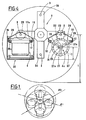
- the washing machine substantially consists of a washing tank 1 within which a rotating element or rotor 2 rotates, which rotor is provided with a number of arms 34 from the free ends of which as many supporting rods or pivots 3 lead off that are adapted to support a plurality of baskets 4-4a designed to contain the pieces to be washed.
- the washing tank 1 is provided, in the region of its charging mouth, with a structure 36 slidably supporting baskets 4-4a to be brought into the washing tank 1.
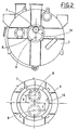
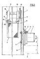
- the washing tank 1 is provided, in an eccentric position with respect to its axis 9, with an opening 10 (see Fig. 3) which can be closed by a flange 6 in turn provided with an eccentric hole adapted to be passed through (see Fig. 2) by a hub 7 of the rotating element 2.
- the eccentricity E of opening 10 with respect to the axis of the washing tank 1 is identical with the eccentricity D of hole 11 to the axis of flange 6 (see detail shown in Figs. 2 and 3).
- Flange 6 can take, relative to the washing tank 1, two different configurations rotated through 180° with respect to each other and corresponding the former to the maximum eccentricity (equal to E + D) of the hole 11 of flange 6 relative to the axis 9 of the washing tank 1 (see detail shown in Fig. 2 in full line and in Fig. 3), the latter corresponding to the coaxial relationship between said hole and axis (see detail shown in Fig. 2 in interrupted line).
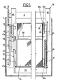
- each rod 3 of the rotating element 2 supports a swinging frame 15 (see Figs. 3, 4 and 5).
- Each frame 15 consists of two rocker arms 35 articulated to the respective rod 3 at a central point thereof and without any possibility of sliding. They are connected to each other by two parallel substantially L-shaped guides 16, integral to their free ends. A gear wheel 23 is keyed on rod 3 in the vicinity of the rocker arm 35 which is closer to the respective arm 34, for the purposes to be clarified in the following.
- Guides 16 are disposed in faced relationship and they are capable of slidably supporting sliding elements 17 associated with the supporting structure 18 of the containing baskets 4.
- Structure 18 in the case of hanging and non-rotating containing baskets 4 (see Figs. 3 and 4) consists of two channel sections engaged to the longitudinal side walls of the containing baskets 4.
- To said channel sections are integral the stems 17a of rollers constituting said sliding elements 17 of basket 4 as well as one or more locking members 24 consisting for example of a spring pin 25a adapted to enter a corresponding hole in guides 16 (see Figs. 3, 4 and 5) in order to prevent basket 4 from sliding relative to guides 16 when the machine is running.
- the containing baskets 4 are of the drawer type (see Figs. 3 and 4) and the channel sections 18 are integral thereto in the region of their upper edges.
- the weight of each containing basket 4 added to that of the pieces contained therein generates a torque in the respective frame 15, which torque during the rotation of the rotating element 2 causes the same to rotate about the correspon d ing rod 3 so as to maintain the inclination of the containing basket 4 unchanged with respect to tank 1, said basket, for example, always having its bottom in a horizontal position.
- the supporting structure 18 thereof consists, according to the present invention, of a T-shaped element 19 from the ends of the horizontal arms of which sliding elements 17 similar to those already described with reference to baskets 4 lead off, at right angles to the plane of said T-shaped element 19.
- One end of a pivot 20 parallel to rod 3 is applied to the vertical arm 22 of the T-shaped element 19.
- a second rotating element or rotor 21 is fitted on pivot 20 which rotating element is provided with a number of arms 21a (three in the example shown in Fig. 4) from the free ends of which respective supporting rods 26 lead off; they are parallel to pivot 20 and hold a containing basket 4a therebetween.
- the free ends of the supporting rods 26 are connected to each other by an annular element 37 so that the same are not allowed to diverge due to the weight of the containing basket 4a and of the pieces contained therein.
- the second rotating element 21 is integral to pivot 20 and it can freely rotate about its axis and a toothed or runged structure 24 is associated therewith so that it meshes with a gear wheel 23 keyed on the respective rod 3 of the first rotating element 2.
- Each of said rotating containing baskets 4a is preferably of cylindrical form and is open at one of its ends where a closing cover 27 is provided.
- At least two locking elements 28 and 29 are associated with cover 27; they may for example be latches engaged into a hole 30a of a reinforcing rim 30 provided on basket 4a and into a hole 26a of one of the supporting rods 26, respectively.
- basket 4a is engaged with rotor 21 both axially and rotatably and, by effect of the rotation of the main rotor 2 and of the gear wheel 23 meshing with the toothed structure 24, it is caused to rotate about its own axis at a speed which is directly dependent on the rotation speed of the main rotor 2 and on the ratio between the number of teeth of the gear wheel 23 and the number of teeth of the toothed structure 24.
- the rotation of basket 4a it is possible to cause the items contained therein to be submitted to a sort of mixing, which is also promoted by a series of longitudinal ribs or raised portions formed inside the baskets and against which said items temporarily bear during rotation of baskets 4a.
- the second rotating element or rotor 21 can be rigidly carried at the ends of arms 34 belonging to the first rotating element 2 if it is not wished to have baskets 4 or 4a supported in a hanging relationship while needing the baskets to rotate for the purpose of mixing the items contained therein.
- the bottom of said basket 4a can be provided with a number of housings 31 being each adapted to receive one of the arms 21a of the second rotor 21 in a restrained fixing relationship.
- baskets 4a When baskets 4a are supported in this manner it is convenient that the axis of the first rotor 2 be coaxial with axis 9 of tank 1. In order to achieve this condition it is sufficient to rotate the flange 6 through 180° so as to eliminate the eccentricity given by the sum of E + D (see Fig. 2). In this way baskets 4a can be plunged into the same amount of solvent as in the case in which hanging baskets 4 are used since the distance L existing in the previous case between the axis of the main rotor 2 and the solvent level is now reduced to a value of L1.
- the system adopted for the hanging support of baskets 4 and 4a is particularly interesting as regards the problem of standardization and the greater production and operation economy.
- a single swinging frame 15 it is possible to use containing baskets both of the drawer type 4 and of the rotating type 4a either simultaneously or at different moments but anyway without modifying the washing tank.
- opening 10 in the washing tank 1 instead of being eccentric and closed by flange 6, could have bigger sizes relative to the ones shown and be coaxial with the axis 9 of the washing tank 1 and in this case two closing flanges would be provided in place of flange 6, one having a passage hole for hub 7 which is coaxial with axis 9 of the washing tank 1 and the second having a passage hole for hub 7 which is eccentric enough to allow hanging baskets such as 4 and 4a to be used.
- opening 10 could be coaxial with axis 9 of the washing tank 1 and could have sizes allowing it to be closed in two stages either by a flange adapted to support hub 7 coaxially to tank 1 or by a flange adapted to support hub 7 eccentrically as hereinbefore described for the use of hanging baskets.
Landscapes
- Chemical & Material Sciences (AREA)
- Chemical Kinetics & Catalysis (AREA)
- General Chemical & Material Sciences (AREA)
- Engineering & Computer Science (AREA)
- Materials Engineering (AREA)
- Mechanical Engineering (AREA)
- Metallurgy (AREA)
- Organic Chemistry (AREA)
- Cleaning By Liquid Or Steam (AREA)
Claims (10)
Applications Claiming Priority (2)
| Application Number | Priority Date | Filing Date | Title |
|---|---|---|---|
| IT03414/86A IT1192032B (it) | 1986-05-09 | 1986-05-09 | Macchina per il lavaggio di pezzi metallici e non metallici quali minuterie e componenti meccanici |
| IT341486 | 1986-05-09 |
Publications (2)
| Publication Number | Publication Date |
|---|---|
| EP0245215A1 EP0245215A1 (de) | 1987-11-11 |
| EP0245215B1 true EP0245215B1 (de) | 1991-03-06 |
Family
ID=11106824
Family Applications (1)
| Application Number | Title | Priority Date | Filing Date |
|---|---|---|---|
| EP87830135A Expired EP0245215B1 (de) | 1986-05-09 | 1987-04-10 | Vorrichtung zum Reinigen von Metall- und Nichtmetallteilen, wie kleinen Gegenständen und mechanischen Bestandteilen |
Country Status (3)
| Country | Link |
|---|---|
| EP (1) | EP0245215B1 (de) |
| DE (1) | DE3768324D1 (de) |
| IT (1) | IT1192032B (de) |
Family Cites Families (2)
| Publication number | Priority date | Publication date | Assignee | Title |
|---|---|---|---|---|
| DE925031C (de) * | 1952-10-12 | 1955-03-10 | Wacker Chemie Gmbh | Reinigungsvorrichtung |
| DE3300666C3 (de) * | 1982-01-26 | 1998-04-09 | Guido Zucchini | Waschverfahren für metallhaltige und nicht-metallhaltige Teile wie Kleinteile, mechanische Komponenten und Teile für die elektronische Industrie sowie eine Maschine zur Durchführung dieses Verfahrens |
-
1986
- 1986-05-09 IT IT03414/86A patent/IT1192032B/it active
-
1987
- 1987-04-10 EP EP87830135A patent/EP0245215B1/de not_active Expired
- 1987-04-10 DE DE8787830135T patent/DE3768324D1/de not_active Expired - Lifetime
Also Published As
| Publication number | Publication date |
|---|---|
| IT1192032B (it) | 1988-03-31 |
| IT8603414A0 (it) | 1986-05-09 |
| DE3768324D1 (de) | 1991-04-11 |
| EP0245215A1 (de) | 1987-11-11 |
Similar Documents
| Publication | Publication Date | Title |
|---|---|---|
| US4091548A (en) | Door mounted stationary drying rack | |
| US4368748A (en) | Device for degreasing, tumbling and washing of industrially manufactured objects | |
| EP0491576A3 (de) | Druck- und Drehwaschmaschine sowie Waschverfahren unter Verwendung derselben | |
| CA2291309A1 (en) | Drive system for clothes washer | |
| EP0245215B1 (de) | Vorrichtung zum Reinigen von Metall- und Nichtmetallteilen, wie kleinen Gegenständen und mechanischen Bestandteilen | |
| EP0600671B1 (de) | Trommel zum Öffnen von verflochtenen Kleidungsstücken | |
| GB1175748A (en) | Dish-Washing Machines | |
| JP3377609B2 (ja) | 洗浄籠装着装置 | |
| US3306693A (en) | Rack system for dishwasher | |
| CN220099413U (zh) | 一种蒸汽罐 | |
| EP0939150A3 (de) | Offenend-Rotorspinnvorrichtung | |
| US2112225A (en) | Laundry apparatus | |
| US2529297A (en) | Mechanism for loading and unloading | |
| Zucchini | Machine to Wash Metal and Non-Metal Pieces, Such as Small Items and Mechanical Components | |
| SU1074615A1 (ru) | Устройство дл мойки изделий | |
| US2425618A (en) | Garment unloading device | |
| RU1803485C (ru) | Устройство дл крашени текстильных изделий | |
| SU1713691A1 (ru) | Установка дл мойки изделий | |
| US2053189A (en) | Machine for spinning and aftertreating artificial silk | |
| SU1650792A1 (ru) | Барабан дл обработки деталей | |
| SU1697909A1 (ru) | Установка дл расконсервации деталей | |
| SU1397093A1 (ru) | Машина дл мойки изделий | |
| GB539777A (en) | Apparatus for removing oil and grease from metal articles | |
| US4128103A (en) | Degreasing apparatus | |
| JP3495427B2 (ja) | 洗浄籠装着装置 |
Legal Events
| Date | Code | Title | Description |
|---|---|---|---|
| PUAI | Public reference made under article 153(3) epc to a published international application that has entered the european phase |
Free format text: ORIGINAL CODE: 0009012 |
|
| AK | Designated contracting states |
Kind code of ref document: A1 Designated state(s): DE FR GB |
|
| 17P | Request for examination filed |
Effective date: 19871105 |
|
| 17Q | First examination report despatched |
Effective date: 19900122 |
|
| GRAA | (expected) grant |
Free format text: ORIGINAL CODE: 0009210 |
|
| AK | Designated contracting states |
Kind code of ref document: B1 Designated state(s): DE FR GB |
|
| ET | Fr: translation filed | ||
| REF | Corresponds to: |
Ref document number: 3768324 Country of ref document: DE Date of ref document: 19910411 |
|
| PLBE | No opposition filed within time limit |
Free format text: ORIGINAL CODE: 0009261 |
|
| STAA | Information on the status of an ep patent application or granted ep patent |
Free format text: STATUS: NO OPPOSITION FILED WITHIN TIME LIMIT |
|
| 26N | No opposition filed | ||
| PGFP | Annual fee paid to national office [announced via postgrant information from national office to epo] |
Ref country code: GB Payment date: 20010425 Year of fee payment: 15 |
|
| PGFP | Annual fee paid to national office [announced via postgrant information from national office to epo] |
Ref country code: DE Payment date: 20010430 Year of fee payment: 15 |
|
| PGFP | Annual fee paid to national office [announced via postgrant information from national office to epo] |
Ref country code: FR Payment date: 20010510 Year of fee payment: 15 |
|
| REG | Reference to a national code |
Ref country code: GB Ref legal event code: IF02 |
|
| PG25 | Lapsed in a contracting state [announced via postgrant information from national office to epo] |
Ref country code: GB Free format text: LAPSE BECAUSE OF NON-PAYMENT OF DUE FEES Effective date: 20020410 |
|
| PG25 | Lapsed in a contracting state [announced via postgrant information from national office to epo] |
Ref country code: DE Free format text: LAPSE BECAUSE OF NON-PAYMENT OF DUE FEES Effective date: 20021101 |
|
| GBPC | Gb: european patent ceased through non-payment of renewal fee |
Effective date: 20020410 |
|
| PG25 | Lapsed in a contracting state [announced via postgrant information from national office to epo] |
Ref country code: FR Free format text: LAPSE BECAUSE OF NON-PAYMENT OF DUE FEES Effective date: 20021231 |
|
| REG | Reference to a national code |
Ref country code: FR Ref legal event code: ST |