EP0245121A1 - Escape mechanism for an upright piano - Google Patents
Escape mechanism for an upright piano Download PDFInfo
- Publication number
- EP0245121A1 EP0245121A1 EP87400311A EP87400311A EP0245121A1 EP 0245121 A1 EP0245121 A1 EP 0245121A1 EP 87400311 A EP87400311 A EP 87400311A EP 87400311 A EP87400311 A EP 87400311A EP 0245121 A1 EP0245121 A1 EP 0245121A1
- Authority
- EP
- European Patent Office
- Prior art keywords
- exhaust
- key
- hammer
- nut
- compression
- Prior art date
- Legal status (The legal status is an assumption and is not a legal conclusion. Google has not performed a legal analysis and makes no representation as to the accuracy of the status listed.)
- Granted
Links
Images
Classifications
-
- G—PHYSICS
- G10—MUSICAL INSTRUMENTS; ACOUSTICS
- G10C—PIANOS, HARPSICHORDS, SPINETS OR SIMILAR STRINGED MUSICAL INSTRUMENTS WITH ONE OR MORE KEYBOARDS
- G10C3/00—Details or accessories
- G10C3/16—Actions
- G10C3/24—Repetition [tremolo] mechanisms
Landscapes
- Physics & Mathematics (AREA)
- Engineering & Computer Science (AREA)
- Acoustics & Sound (AREA)
- Multimedia (AREA)
- Stringed Musical Instruments (AREA)
- Electrophonic Musical Instruments (AREA)
- Exhaust Silencers (AREA)
- Toys (AREA)
- Auxiliary Devices For Music (AREA)
- Springs (AREA)
Abstract
Description
La présente invention se rapporte à un mécanisme d'échappement destiné à un piano droit.The present invention relates to an exhaust mechanism for an upright piano.
Le piano, bien que sa mise au point soit relativement récente (vers les années 1700), est l'instrument de musique le plus universellement répandu.The piano, although it was developed relatively recently (around the 1700s), is the most universally used musical instrument.
Il est bien connu que les pianos donnent des sons grâce à un ensemble de cordes d'acier tendues sur une table de résonance et mises en vibrations par le choc de marteaux garnis de feutre, actionnés chacun par la compression d'une touche d'un clavier qui les déplace entre une position de repos et une position de frappe dans laquelle ils sont en contact avec les cordes par l'intermédiaire d'un mécanisme d'attaque.It is well known that pianos give sounds thanks to a set of steel strings stretched over a resonance table and set in vibration by the impact of hammers furnished with felt, each actuated by the compression of a touch of a keyboard which moves them between a rest position and a striking position in which they are in contact with the strings by means of an attack mechanism.
On distingue deux types principaux de pianos qui sont les pianos dits "à queue" dans lesquels les cordes sont disposées horizontalement et les pianos dits "droits" dans lesquels les cordes sont disposées verticalement. L'avantage des pianos à queue sur les pianos droits est lié au fait qu'ils possèdent un mécanisme dit "à double échappement" qui permet à un joueur de venir frapper une touche immédiatement après qu'elle ait été lâchée ; une telle opération est en effet impossible dans le cas des pianos droits classiques où il est nécessaire d'attendre que la touche soit revenue à sa position initiale avant de rejouer une nouvelle note. Il s'agit là d'un inconvénient très important qui fait que certains pianistes, au jeu particulièrement rapide, ne peuvent pas jouer sur des pianos droits.There are two main types of pianos which are the so-called "grand" pianos in which the strings are arranged horizontally and the so-called "upright" pianos in which the strings are arranged vertically. The advantage of grand pianos over upright pianos is linked to the fact that they have a mechanism known as "double escapement" which allows a player to come and strike a key immediately after it has been released; such an operation is indeed impossible in the case of conventional upright pianos where it is necessary to wait until the key has returned to its initial position before replaying a new note. This is a very significant drawback which means that some pianists, who play particularly quickly, cannot play on upright pianos.
Cet inconvénient est lié avant tout à la configuration du mécanisme d'attaque sus-mentionné qui comprend entre autres au étouffoir qui empêche le son de se prolonger après actionnement de la touche, ainsi que le mécanisme d'échappement qui permet aux marteaux de se déplacer vers leur position de frappe et de revenir à leur position de repos après compression de la touche correspondante pour permettre un nouvel actionnement.This drawback is linked above all to the configuration of the aforementioned attack mechanism which includes inter alia the damper which prevents the sound from being prolonged after actuation of the key, as well as the exhaust mechanism which allows the hammers to move towards their striking position and return to their rest position after pressing the corresponding button to allow a new actuation.
Le mécanisme d'échappement des pianos droits comporte, pour chacune des touches, un chevalet formant levier coopérant avec la touche pour amener le marteau en position de frappe lors de la compression de cette dernière et sur lequel sont montés, d'une part, un sommier de mécanique fixe, sur lequel est articulée une noix portant le marteau, et d'autre part, un montant d'échappement approximativement vertical mobile entre une position d'attaque qu'il occupe lorsque le marteau est en position de repos et dans laquelle il se trouve au-dessous de la noix et en prise avec cette dernière pour commander son déplacement et, par suite, celui du marteau vers sa position de frappe en réponse à la compression de la touche, et une position de retrait qu'il occupe lorsque le marteau se déplace de sa position de repos à sa position de frappe ou vice versa et dans laquelle il est indépendant de la noix.The exhaust mechanism of upright pianos comprises, for each of the keys, a bridge forming a lever cooperating with the key to bring the hammer into the striking position during the compression of the latter and on which are mounted, on the one hand, a fixed mechanical bed base, on which is articulated a nut carrying the hammer, and on the other hand, an approximately vertical exhaust amount movable between an attack position which it occupies when the hammer is in the rest position and in which it is below the nut and engaged with the latter to control its movement and, consequently, that of the hammer towards its striking position in response to the compression of the key, and a withdrawal position which it occupies when the hammer moves from its rest position to its striking position or vice versa and in which it is independent of the nut.
Le mécanisme susmentionné donne au piano sa douceur de toucher et sa sensibilité, mais présente l'inconvénient s'il ne comporte pas d'organe complémentaire, d'obliger à attendre que la touche ait repris sa position initiale avant compression pour que le montant d'échappement se trouve à nouveau en prise avec la noix, en position d'attaque, et pour que l'on puisse à nouveau venir frapper les cordes avec le marteau afin d'obtenir un nouveau son.The aforementioned mechanism gives the piano its softness of touch and its sensitivity, but has the disadvantage if it does not include an additional organ, of obliging to wait until the key has returned to its initial position before compression so that the exhaust amount is again engaged with the nut, in the attack position, and so that one can again come and strike the strings with the hammer in order to obtain a new sound.
Cet inconvénient fait que, malgré leurs avantages liés principalement à leur encombrement réduit, les pianos droits sont toujours, si possible, délaissés au profit des pianos à queue.This drawback means that, despite their advantages linked mainly to their reduced size, upright pianos are always, if possible, abandoned in favor of grand pianos.
Pour remédier à cet inconvénient, on a dépuis longtemps tenté de munir les mécanismes d'échappement des pianos droits, d'organes supplémentaires ayant pour but d'accélérer après frappe le retour du montant d'échappement vers sa position d'attaque. Les dispositifs de ce type qui ont été proposés se sont cependant toujours avérés relativement compliqués, et aucun n'a en fait pu donner entière satisfaction. Parmi ces dispositifs, on peut mentionner à titre d'exemple, l'adjonction au-dessous du montant d'échappement, d'un ressort hélicoïdal couplé à un ressort-lame disposé le long du montant d'échappement et coopérant avec une butée supplémentaire sur laquelle il s'appuie ; ce système offre l'avantage de permettre d'accélérer dans une large mesure le retour du montant d'échappement vers sa position d'attaque, mais présente l'inconvénient d'augmenter le nombre des pièces du mécanisme d'attaque, ce qui entraîne une gêne importante pour le réglage des 88 touches du piano.To remedy this drawback, attempts have been made for a long time to provide the exhaust mechanisms of upright pianos, with additional members intended to accelerate after striking the return of the exhaust amount to its attack position. The devices of this type which have been proposed have however always proved to be relatively complicated, and none has in fact been able to give complete satisfaction. Among these devices, one can mention by way of example, the addition below the exhaust post, of a helical spring coupled to a leaf spring arranged along the exhaust post and cooperating with an additional stop on which it is based; this system offers the advantage of making it possible to speed up to a large extent the return of the exhaust post to its attack position, but has the drawback of increasing the number of parts of the attack mechanism, which leads to a significant annoyance for the adjustment of the 88 keys of the piano.
La présente invention a pour objet de remédier à ces inconvénients en proposant un mécanisme d'échappement destiné à un paino droit, permettant d'augmenter dans une large mesure la vitesse de retour du montant d'échappement vers sa position d'attaque, permettant par suite de rapprocher les caractéristiques d'un piano droit à celles d'un piano à queue, et ce, tout en limitant le nombre de pièces complémentaires nécessaires.The object of the present invention is to remedy these drawbacks by proposing an exhaust mechanism intended for a straight paino, making it possible to increase to a large extent the speed of return of the exhaust upright towards its attack position, allowing by following to bring the characteristics of an upright piano closer to those of a grand piano, while limiting the number of additional parts required.
A cet effet, le mécanisme d'échappement conforme à l'invention est caractérisé en ce qu'il comporte un ressort de répétition à lame replié en forme de U et dont l'une des branches ou première branche est fixée à la partie supérieure du montant d'échappement (7) et s'étend de haut en bas le long de ce dernier et dont l'autre branche ou seconde branche coopère à sa partie supérieure avec une butée de répétition solidaire du sommier de mécanique pour ramener le montant d'échappement en position d'attaque, au-dessous de la noix en réponse à une remontée minime de la touche après compression de cette dernière.To this end, the exhaust mechanism according to the invention is characterized in that it comprises a repetition spring with leaf folded in the shape of a U and one of the branches or first branch of which is fixed to the upper part of the exhaust amount (7) and extends from top to bottom along the latter and of which the other branch or second branch cooperates at its upper part with a repetition stop integral with the mechanical bed base to bring the amount of escapement in the attack position, below the nut in response to a minimal ascent of the fingerboard after compression of the latter.
Ainsi, pour une remontée minime de la touche après enfoncement, le ressort de répétition, qui a été préalablement mis sous tension par suite de la compression de la touche, exerce sur le montant d'échappement une force lui permettant de revenir automatiquemnet à sa position d'attaque en repoussant le marteau vers les cordes. Il s'agit là d'une configuration particulièrement simple ne nécessitant l'adjonction que d'un seul élément supplémentaire, à savoir le ressort de répétition.Thus, for a minimal ascent of the key after being pressed, the repetition spring, which has been previously tensioned as a result of the compression of the key, exerts on the exhaust post a force allowing it to return automatically to its position attack by pushing the hammer towards the strings. This is a particularly simple configuration requiring the addition of only one additional element, namely the repetition spring.
Selon une autre caractéristique de l'invention, le montant d'échappement comporte, à sa partie inférieure, un bourrelet arrière relié au chevalet par un ressort d'échappement.According to another characteristic of the invention, the exhaust upright comprises, at its lower part, a rear bead connected to the bridge by an exhaust spring.
Cette caractéristique permet d'augmenter la vitesse de retour du montant d'échappement vers sa position d'attaque grâce à la force de rappel du ressort d'échappement.This characteristic makes it possible to increase the speed of return of the exhaust upright towards its attack position thanks to the return force of the exhaust spring.
Cette configuration s'est avérée comme étant particulièrement satisfaisante du point de vue de la facilité de réglage du piano.This configuration has been found to be particularly satisfactory from the point of view of the ease of adjustment of the piano.
Selon une autre caractéristique de l'invention, la butée de répétition est recouverte de feutre en regard du ressort de répétition. Cette caractéristique permet d'augmenter la douceur du piano.According to another characteristic of the invention, the repetition stopper is covered with felt next to the repeat spring. This characteristic increases the softness of the piano.
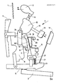
Les caractéristiques du mécanisme d'échappement destiné à un piano droit qui fait l'objet de l'invention, seront décrites plus en détail en se référant au dessin annexé qui est un schéma représentant le mécanisme associé à chacune des touches du piano.The characteristics of the escape mechanism intended for an upright piano which is the subject of the invention will be described in more detail with reference to the appended drawing which is a diagram representing the mechanism associated with each of the keys of the piano.
Selon la figure, un piano droit est constitué par un ensemble de cordes d'acier 1, disposées verticalement et tendues sur une table de résonance non représentée. Ces cordes sont mises en vibration par suite du choc de marteaux 2 garnis de feutre, qui sont actionnés chacun par la compression d'une touche 3 d'un clavier. La compression selon la flèche A d'une touche 3 entraîne le déplacement du marteau 2 d'une position de repos représentée sur la figure, à une position de frappe dans laquelle il se déplace selon la flèche B pour venir en contact avec la corde 1. Le mouvement de la touche 3 est transmis au marteau 2 par l'intermédiaire d'un mécanisme d'attaque qui comprend de nombreuses pièces parmi lesquelles on peut mentionner l'étouffoir 4 qui empêche le son de se prolonger quand on quitte la touche et l'ensemble I du mécanisme d'échappement qui fait l'objet du présent brevet et donne au piano sa douceur de toucher, sa sensibilité et sa faculté de répétition rapide.According to the figure, an upright piano consists of a set of steel strings 1, arranged vertically and stretched on a resonance table not shown. These strings are set in vibration as a result of the impact of
Selon la figure, le mécanisme d'echappement I comporte un chevalet 5 formant levier pivotant sur lequel pousse la touche 3 lors de sa compression selon la flèche A, et sur lequel est monté un sommier de mécanique fixe 6 ainsi qu'un montant d'échappement 7 articulé autour d'un axe 21 et comportant, à sa partie inférieure, un bourrelet arrière 22 relié au chevalet 5 par un ressort d'échappement 23. Une barre d'échap pement 8 est, par ailleurs, reliée solidairement à une tige métallique 9 au sommier de mécanique 6.According to the figure, the escapement mechanism I comprises an
Une noix 10 portant un axe 11 à l'extrémité duquel est fixé le marteau 2 est, en outre, articulée sur le sommier de mécanique 6 ; celle-ci porte approximativement perpendiculairement à l'axe 11 portant le marteau 2, un axe 12 à l'extrémité duquel est fixée une contre-attrape 13 coopérant lorsque le marteau 2 se déplace selon la flèche B vers sa position de frappe avec une attrape 14 qui est fixée directement sur le chevalet 5. A la fin du déplacement du marteau 2 selon la flèche B, la contre-attrape 13 vient selon la flèche C en contact avec l'attrape 14 pour toujours maintenir le marteau 2 à une petite distance de la corde 1.A
Dans la position de repos représentée sur la figure, le montant d'échappement 7 se trouve dans une position d'attaque dans laquelle il se trouve juste en dessous de la noix 10 et en prise par son extrémité 15 avec cette dernière pour la pousser vers l'avant (flèche B) en réponse à une compression de la touche 3 (flèche A). Pendant ce mouvement, ainsi que le mouvement correspondant de retour de la touche 3 et du marteau 2 vers leur position de repos, le montant d'échappement 7 se trouve dans une position de retrait dans laquelle son extrémité 15 n'est pas en contact avec la noix 10, et donc, dans laquelle il est impossible à l'utilisateur du piano de rejouer une nouvelle note en comprimant la touche 3 selon la flèche A.In the rest position shown in the figure, the
Conformément à l'invention, on cherche justement à réduire ce laps de temps pendant lequel il est impossible de rejouer ; à cet effet, un ressort de répétition 16 replié en forme de U est fixé par l'extrémité supérieure 17 de sa première branche 160 à l'extrémité supérieure du montant d'échappement 7 et s'étend de haut en bas le long de ce dernier ; l'extrémité supérieure 18 de la seconde branche 161 du ressort 16 vient en appui, pendant le déplacement du marteau 2 vers sa position de frappe (flècheB), contre une butée de répétition 19 solidaire du sommier de mécanique 6 auquel elle est reliée par une tige métallique 24 et recouverte d'un feutre 20 en regard de ce ressort. En conséquence, lorsque le marteau 2 est en position de frappe, le ressort de répétition 16 se trouve sous tension, et exerce lors du relâchement de la touche 3, une force D sur le montant d'échappement 17 qui tend à le ramener rapidement dans sa position d'attaque dans laquelle il se trouve au-dessous de la noix 10 et coopère par son extrémité 15 avec cette dernière pour permettre de rejouer très rapidement.In accordance with the invention, it is precisely sought to reduce this period of time during which it is impossible to replay; for this purpose, a
L'invention permet donc en fait au pianiste de pouvoir rejouer pratiquement immédiatement après compression d'une touche grâce à l'adjonction d'une seule pièce (ressort de répétition 16).The invention therefore in fact allows the pianist to be able to replay practically immediately after pressing a key thanks to the addition of a single piece (repetition spring 16).
Claims (3)
Priority Applications (1)
| Application Number | Priority Date | Filing Date | Title |
|---|---|---|---|
| AT87400311T ATE66538T1 (en) | 1986-04-30 | 1987-02-12 | ESCAPE MECHANISM FOR A PIANO. |
Applications Claiming Priority (2)
| Application Number | Priority Date | Filing Date | Title |
|---|---|---|---|
| FR8606277 | 1986-04-30 | ||
| FR8606277A FR2598244B1 (en) | 1986-04-30 | 1986-04-30 | EXHAUST MECHANISM FOR A RIGHT PIANO |
Publications (2)
| Publication Number | Publication Date |
|---|---|
| EP0245121A1 true EP0245121A1 (en) | 1987-11-11 |
| EP0245121B1 EP0245121B1 (en) | 1991-08-21 |
Family
ID=9334792
Family Applications (1)
| Application Number | Title | Priority Date | Filing Date |
|---|---|---|---|
| EP87400311A Expired - Lifetime EP0245121B1 (en) | 1986-04-30 | 1987-02-12 | Escape mechanism for an upright piano |
Country Status (5)
| Country | Link |
|---|---|
| EP (1) | EP0245121B1 (en) |
| AT (1) | ATE66538T1 (en) |
| DE (1) | DE3772252D1 (en) |
| ES (1) | ES2025674T3 (en) |
| FR (1) | FR2598244B1 (en) |
Cited By (1)
| Publication number | Priority date | Publication date | Assignee | Title |
|---|---|---|---|---|
| AU643398B2 (en) * | 1987-12-01 | 1993-11-11 | Anthony Gerald Caught | Improved upright piano |
Citations (4)
| Publication number | Priority date | Publication date | Assignee | Title |
|---|---|---|---|---|
| DE195842C (en) * | ||||
| FR412216A (en) * | 1910-02-01 | 1910-07-07 | Emile Souhami | Improvements in the mechanics of upright pianos |
| GB191010969A (en) * | 1909-10-21 | 1910-12-22 | Joseph Herrburger | Improvements in or relating to Repetition Mechanism in Pianos and like Instruments. |
| US3100416A (en) * | 1960-04-18 | 1963-08-13 | Wurlitzer Co | Piano action |
-
1986
- 1986-04-30 FR FR8606277A patent/FR2598244B1/en not_active Expired
-
1987
- 1987-02-12 DE DE8787400311T patent/DE3772252D1/en not_active Expired - Lifetime
- 1987-02-12 EP EP87400311A patent/EP0245121B1/en not_active Expired - Lifetime
- 1987-02-12 AT AT87400311T patent/ATE66538T1/en active
- 1987-02-12 ES ES198787400311T patent/ES2025674T3/en not_active Expired - Lifetime
Patent Citations (4)
| Publication number | Priority date | Publication date | Assignee | Title |
|---|---|---|---|---|
| DE195842C (en) * | ||||
| GB191010969A (en) * | 1909-10-21 | 1910-12-22 | Joseph Herrburger | Improvements in or relating to Repetition Mechanism in Pianos and like Instruments. |
| FR412216A (en) * | 1910-02-01 | 1910-07-07 | Emile Souhami | Improvements in the mechanics of upright pianos |
| US3100416A (en) * | 1960-04-18 | 1963-08-13 | Wurlitzer Co | Piano action |
Cited By (1)
| Publication number | Priority date | Publication date | Assignee | Title |
|---|---|---|---|---|
| AU643398B2 (en) * | 1987-12-01 | 1993-11-11 | Anthony Gerald Caught | Improved upright piano |
Also Published As
| Publication number | Publication date |
|---|---|
| FR2598244B1 (en) | 1989-03-31 |
| ATE66538T1 (en) | 1991-09-15 |
| ES2025674T3 (en) | 1992-04-01 |
| FR2598244A1 (en) | 1987-11-06 |
| DE3772252D1 (en) | 1991-09-26 |
| EP0245121B1 (en) | 1991-08-21 |
Similar Documents
| Publication | Publication Date | Title |
|---|---|---|
| EP0126127B1 (en) | String support and neck device for stringed and neck instrument | |
| EP0807303B1 (en) | Musical method for musical instruments such as pianos, and mechanism therefor | |
| JP3430638B2 (en) | Keyboard instrument | |
| JP3463365B2 (en) | Keyboard instrument | |
| EP0384837B1 (en) | Damping mechanism for an upright piano | |
| JPH07219522A (en) | Keyboard musical instrument | |
| EP3053160B1 (en) | Piano extended soft pedal | |
| WO2007006967A1 (en) | Novel ligature for reed-mouthpiece musical instrument | |
| EP0245121B1 (en) | Escape mechanism for an upright piano | |
| FR2590061A1 (en) | Escapement mechanism for an upright piano | |
| FR2652186A1 (en) | Upright pianos with improved action | |
| JP3714349B2 (en) | Silencer for keyboard instrument and keyboard instrument | |
| BE509259A (en) | ||
| FR2599880A1 (en) | NOVEL MUSICAL PROCESS FOR STRIKING INSTRUMENTS OR SIMILAR INSTRUMENTS AND PEDAL MECHANISM SUITABLE FOR THIS NEW PROCESS | |
| EP0229746A2 (en) | Return mechanism for an upright piano and means for its application | |
| JPS6243353Y2 (en) | ||
| JPH08328546A (en) | Keyboard device of electronic musical instrument | |
| CH104122A (en) | Piano. | |
| FR2719694A1 (en) | Bell carillon ringing mechanism | |
| FR2846455A1 (en) | Device for facilitating adjustment of the action of an upright piano includes regulating screw and rod for adjusting the tension of a sprung steel device stretched from front part of felt | |
| JPH07234669A (en) | Keyboard musical instrument | |
| BE475552A (en) | ||
| FR2823360A1 (en) | Push button activated stringed musical instrument having push buttons activating strings through harmony table and having hold/release mechanism pressurising/releasing string pressure. | |
| US323632A (en) | Piano-action | |
| US20060174751A1 (en) | Pivotal mechanism of a swinging structure of a cymbal pedal |
Legal Events
| Date | Code | Title | Description |
|---|---|---|---|
| PUAI | Public reference made under article 153(3) epc to a published international application that has entered the european phase |
Free format text: ORIGINAL CODE: 0009012 |
|
| AK | Designated contracting states |
Kind code of ref document: A1 Designated state(s): AT BE CH DE ES GB GR IT LI LU NL SE |
|
| 17P | Request for examination filed |
Effective date: 19880118 |
|
| 17Q | First examination report despatched |
Effective date: 19900319 |
|
| GRAA | (expected) grant |
Free format text: ORIGINAL CODE: 0009210 |
|
| AK | Designated contracting states |
Kind code of ref document: B1 Designated state(s): AT BE CH DE ES GB GR IT LI LU NL SE |
|
| PG25 | Lapsed in a contracting state [announced via postgrant information from national office to epo] |
Ref country code: SE Effective date: 19910821 Ref country code: GR Free format text: LAPSE BECAUSE OF FAILURE TO SUBMIT A TRANSLATION OF THE DESCRIPTION OR TO PAY THE FEE WITHIN THE PRESCRIBED TIME-LIMIT Effective date: 19910821 Ref country code: AT Effective date: 19910821 |
|
| REF | Corresponds to: |
Ref document number: 66538 Country of ref document: AT Date of ref document: 19910915 Kind code of ref document: T |
|
| REF | Corresponds to: |
Ref document number: 3772252 Country of ref document: DE Date of ref document: 19910926 |
|
| ITF | It: translation for a ep patent filed |
Owner name: STUDIO TORTA SOCIETA' SEMPLICE |
|
| GBT | Gb: translation of ep patent filed (gb section 77(6)(a)/1977) | ||
| PG25 | Lapsed in a contracting state [announced via postgrant information from national office to epo] |
Ref country code: BE Effective date: 19920228 |
|
| PG25 | Lapsed in a contracting state [announced via postgrant information from national office to epo] |
Ref country code: LU Free format text: LAPSE BECAUSE OF NON-PAYMENT OF DUE FEES Effective date: 19920229 Ref country code: LI Effective date: 19920229 Ref country code: CH Effective date: 19920229 |
|
| REG | Reference to a national code |
Ref country code: ES Ref legal event code: FG2A Ref document number: 2025674 Country of ref document: ES Kind code of ref document: T3 |
|
| PLBE | No opposition filed within time limit |
Free format text: ORIGINAL CODE: 0009261 |
|
| STAA | Information on the status of an ep patent application or granted ep patent |
Free format text: STATUS: NO OPPOSITION FILED WITHIN TIME LIMIT |
|
| 26N | No opposition filed | ||
| BERE | Be: lapsed |
Owner name: GOMBAULT GILBERT Effective date: 19920228 |
|
| REG | Reference to a national code |
Ref country code: CH Ref legal event code: PL |
|
| PGFP | Annual fee paid to national office [announced via postgrant information from national office to epo] |
Ref country code: GB Payment date: 19930212 Year of fee payment: 7 |
|
| PGFP | Annual fee paid to national office [announced via postgrant information from national office to epo] |
Ref country code: ES Payment date: 19930218 Year of fee payment: 7 |
|
| PGFP | Annual fee paid to national office [announced via postgrant information from national office to epo] |
Ref country code: NL Payment date: 19930228 Year of fee payment: 7 |
|
| PG25 | Lapsed in a contracting state [announced via postgrant information from national office to epo] |
Ref country code: GB Effective date: 19940212 |
|
| PG25 | Lapsed in a contracting state [announced via postgrant information from national office to epo] |
Ref country code: ES Free format text: LAPSE BECAUSE OF NON-PAYMENT OF DUE FEES Effective date: 19940214 |
|
| PG25 | Lapsed in a contracting state [announced via postgrant information from national office to epo] |
Ref country code: NL Effective date: 19940901 |
|
| GBPC | Gb: european patent ceased through non-payment of renewal fee |
Effective date: 19940212 |
|
| NLV4 | Nl: lapsed or anulled due to non-payment of the annual fee | ||
| PGFP | Annual fee paid to national office [announced via postgrant information from national office to epo] |
Ref country code: DE Payment date: 19970222 Year of fee payment: 11 |
|
| PG25 | Lapsed in a contracting state [announced via postgrant information from national office to epo] |
Ref country code: DE Free format text: LAPSE BECAUSE OF NON-PAYMENT OF DUE FEES Effective date: 19981103 |
|
| REG | Reference to a national code |
Ref country code: ES Ref legal event code: FD2A Effective date: 19990201 |
|
| PG25 | Lapsed in a contracting state [announced via postgrant information from national office to epo] |
Ref country code: IT Free format text: LAPSE BECAUSE OF NON-PAYMENT OF DUE FEES;WARNING: LAPSES OF ITALIAN PATENTS WITH EFFECTIVE DATE BEFORE 2007 MAY HAVE OCCURRED AT ANY TIME BEFORE 2007. THE CORRECT EFFECTIVE DATE MAY BE DIFFERENT FROM THE ONE RECORDED. Effective date: 20050212 |