EP0244909B1 - High-pressure sodium vapour discharge lamp - Google Patents
High-pressure sodium vapour discharge lamp Download PDFInfo
- Publication number
- EP0244909B1 EP0244909B1 EP87200808A EP87200808A EP0244909B1 EP 0244909 B1 EP0244909 B1 EP 0244909B1 EP 87200808 A EP87200808 A EP 87200808A EP 87200808 A EP87200808 A EP 87200808A EP 0244909 B1 EP0244909 B1 EP 0244909B1
- Authority
- EP
- European Patent Office
- Prior art keywords
- lamp
- discharge vessel
- electrodes
- pressure sodium
- lamps
- Prior art date
- Legal status (The legal status is an assumption and is not a legal conclusion. Google has not performed a legal analysis and makes no representation as to the accuracy of the status listed.)
- Expired
Links
Images
Classifications
-
- H—ELECTRICITY
- H01—ELECTRIC ELEMENTS
- H01J—ELECTRIC DISCHARGE TUBES OR DISCHARGE LAMPS
- H01J61/00—Gas-discharge or vapour-discharge lamps
- H01J61/82—Lamps with high-pressure unconstricted discharge having a cold pressure > 400 Torr
- H01J61/825—High-pressure sodium lamps
Description
- The invention relates to a high-pressure sodium vapour discharge lamp provided with a sealed ceramic discharge vessel which has over a length L an at least substantially constant inner diameter, - in which discharge vessel electrodes are arranged opposite to each other at a relative distance D and are connected to a respective current-supply conductor, which extends through the wall of the discharge vessel to the exterior, - which discharge vessel has a filling which comprises sodium and rare gas, - which lamp consumes during operation a power of at most 50 W and emits light having a colour temperature of at least 2250 K. Such a lamp is known from British Patent Specification 20,83,281.
- A lamp of this kind can be used to replace an incandescent lamp. The lamp emits "white light". In general, it holds for the colour temperature (Tc) that 2250 s Tc s 2750 K. The range in the colour triangle within which the light of a high-pressure sodium discharge lamp is designated as "white" is bounded by straight lines through points with the coordinates (x, y): (0.468; 0.430), (0.510; 0.430), (0.485; 0.390) and (0.445; 0.390). According to more stringent standards based on a better acceptation of the light by testees, the light is designated as "white" when its colour point lies in a range of the colour triangle bounded by the lines x = 0.468, x = 0.490, y = 0.408 and y = 0.425. The colour temperature then lies between about 2300 and about 2700 K and the general colour rendition index (Raa) lies between about 70 and about 85.
- Lamps of this kind are attractive as substitutes for incandescent lamps because of their a few times longer life, their a few times higher efficiency, their luminous flux corresponding to that of the larger incandescent lamps (about 60 - 200W) and because of the fact that their light can be readily concentrated.
- A disadvantage of lamps of this kind is that their efficiency is lower than that of high-pressure sodium lamps emitting yellow light (Tα = 1800 - 2000 K), i.e. the lower as the colour temperature is higher. Furthermore, the efficiency decreases with decreasing power.
- The invention has for its object to provide a lamp of the kind described in the opening paragraph, which at a given colour temperature and a given power has a higher efficiency than a similar known lamp having that colour temperature and that power.
- According to the invention, this object is achieved in a lamp of the kind described in the opening paragraph in the D/L s 0.5.
- The lamp according to the invention generally has a power in the range of 20 - 50 W. Lamps having a considerably lower power can be obtained only with difficulty by the known means. In order to prevent very high currents and hence high losses in the ballast of the lamp, the electrode distance D is generally at least 3 mm. On the other hand, the generated light can be better concentrated when the discharge arc is not very long. The electrode distance D consequently lies generally between 2 and 13 mm. In general, the ratio D/L lies in the range of 0.15 - 0.5. With smaller ratios, the gain in efficiency of the lamp decreases due to higher thermal losses at the ends of the discharge vessel and higher losses at the electrodes. With considerably larger ratios, there is no or substantially no gain in efficiency.
- The term "ceramic" is to be understood to mean; a monocrystalline or polycrystalline material, such as sapphire, or translucent sintered aluminium oxide.
- The lamp according to the invention can be operated in air or in a gas-filled or evacuated outer bulb.
- Embodiments of the lamp according to the invention are shown in the drawing. In the drawing:
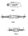
- Fig. 1 is a side elevation of a lamp with an outer bulb,
- Fig. 2 is a longitudinal sectional view of a lamp,
- Fig. 3 is a longitudinal sectional view of another lamp,
- In Fig. 1, the lamp has a sealed
ceramic discharge vessel 1, which has over a length L an at least substantially constant inner diameter. In thedischarge vessel 1electrodes supply conductor discharge vessel 1, The ratio D/L s 0.5. Thedischarge vessel 1 is fitted with sodium, mercury and rare gas. Thedischarge vessel 1 is arranged in anouter bulb 6, which has alamp cap 7, to which the current-supply conductors - In figures 2 and 3, corresponding parts have a reference numeral which is 10 and 20, respectively, higher than in Fig. 1. Like in Fig. 12, in these Figures D/L s 0.5. The
discharge vessel electrodes supply conductors discharge vessels ceramics - From discharge vessels of the shape shown in Fig. 2 lamps were manufactured, which has different distances (D) between the tops of the pin-shaped electrodes, which has a diameter ⌀ and which had different lengths (L) over which the discharge vessel had an at least substantial constant inner diameter of 2.5 mm. The discharge vessels were filled with Na/Hg = 15/40 (weight/weight) and with xenon at a pressure of 50 kPa at 300 K, the lamps were operated in an evacuated outer bulb and their efficiency was measured. The colour temperature of the generated light was 2450 K. The lamps were compared with a lamp having the same colour temperature (No. 11) of Example 1 of the aforementioned British Patent Specification 20,83,281. There was further compared with a lamp (No. 12) which does not satisfy the requirement imposed according to the invention. These lamps (Nrs. 11 and 12) also had an evacuated outer bulb. The results are stated in Table 1.

- A considerable increase in efficiency for lamps according to the invention appears from these data in comparison with the known lamp (No. 11) and the lamp (No. 12) not satisfying the maximum of D/L.
- For explanation of the results in Table 1, the following should be noted. When the distance (D) between the electrodes is smaller, a larger current must flow through the lamp to dissipate therein the same quantity of energy. Due to the higher current, the temperature of the electrodes increases. Evaporation of electrode material can the lead to a more rapid blackening of the discharge vessel. In order to avoid this, electrodes of a larger diameter can be used. The use of thicker electrodes leads to higher losses in the electrodes and hence to a lower efficiency, however. This appears when comparing the
lamps - If, however, the envisaged use of the lamp makes it desirable to have a small distance between the electrodes, in order to avoid blackening, thicker electrodes will be chosen and a decrease of the efficiency will be accepted. However, as appears from Table 1, the lamp according to the invention yields, even with a smaller distance between the electrodes LD) and with the use of thick electrodes, a high efficiency as compared with lamps not in accordance with the invention (compare
lamp 7 withlamps 11 and 12). - European Patent Application 0 094 137 discloses a normal high-pressure sodium lamp (HF 68), i.e. a lamp emitting yellow light having the properties indicated in Table 2 (lamp 21). The same lamp was operated at a power of 50 W (lamp 22). For comparison, data are stated of a 50 W high-pressure sodium lamp (lamp 23), which is commercially available (Philips, SON 50 W, No. 9281 508 088). These lamps have a colour temperature Tc lying between 1800 and 2000 K.

- It appears from Table 2 that with conventional high-pressure sodium lamps having a low colour temperature the efficiency decreases considerably when the ratio D/L satisfies D/L ≤ 0.5. This is in sharp contrast with the increase in efficiency with lamps according to the invention emitting "white light" with D/L ≤ 0.5.
Claims (1)
Applications Claiming Priority (2)
| Application Number | Priority Date | Filing Date | Title |
|---|---|---|---|
| NL8601162 | 1986-05-07 | ||
| NL8601162 | 1986-05-07 |
Publications (2)
| Publication Number | Publication Date |
|---|---|
| EP0244909A1 EP0244909A1 (en) | 1987-11-11 |
| EP0244909B1 true EP0244909B1 (en) | 1990-07-04 |
Family
ID=19847983
Family Applications (1)
| Application Number | Title | Priority Date | Filing Date |
|---|---|---|---|
| EP87200808A Expired EP0244909B1 (en) | 1986-05-07 | 1987-04-29 | High-pressure sodium vapour discharge lamp |
Country Status (7)
| Country | Link |
|---|---|
| US (1) | US4795943A (en) |
| EP (1) | EP0244909B1 (en) |
| JP (1) | JPS62268050A (en) |
| CN (1) | CN1008571B (en) |
| CA (1) | CA1270893A (en) |
| DE (1) | DE3763535D1 (en) |
| HU (1) | HU195027B (en) |
Families Citing this family (9)
| Publication number | Priority date | Publication date | Assignee | Title |
|---|---|---|---|---|
| US4970431A (en) * | 1987-11-03 | 1990-11-13 | U.S. Philips Corporation | High-pressure sodium discharge lamp with fins radially extending from the discharge vessel for controlling the wall temperature of the discharge vessel |
| DE3806805A1 (en) * | 1988-03-03 | 1989-09-14 | Feldmuehle Ag | BELLY BURNER TUBE FOR METAL STEAM DISCHARGE LAMPS |
| US5153482A (en) * | 1990-02-21 | 1992-10-06 | U.S. Philips Corporation | High-pressure sodium discharge lamp |
| US5097176A (en) * | 1990-02-21 | 1992-03-17 | U.S. Philips Corporation | High-pressure sodium discharge lamp having a color temperature of at least 2800° K. |
| US5144201A (en) * | 1990-02-23 | 1992-09-01 | Welch Allyn, Inc. | Low watt metal halide lamp |
| US5184044A (en) * | 1990-08-13 | 1993-02-02 | Welch Allyn, Inc. | Dental curing lamp |
| JPH1040868A (en) * | 1996-07-25 | 1998-02-13 | Ushio Inc | Discharge lamp |
| EP0930639B1 (en) * | 1997-04-11 | 2004-06-30 | Ushio Denki Kabushiki Kaisya | Seal of bulb |
| US7394200B2 (en) * | 2005-11-30 | 2008-07-01 | General Electric Company | Ceramic automotive high intensity discharge lamp |
Family Cites Families (4)
| Publication number | Priority date | Publication date | Assignee | Title |
|---|---|---|---|---|
| US2714687A (en) * | 1950-08-02 | 1955-08-02 | Gen Electric | High pressure mercury vapor electric discharge lamps |
| NL185482C (en) * | 1980-09-05 | 1991-01-16 | Philips Nv | HIGH PRESSURE DISCHARGE LAMP. |
| JPS5750763A (en) * | 1980-09-11 | 1982-03-25 | Matsushita Electronics Corp | High pressure sodium lamp |
| US4527097A (en) * | 1982-05-10 | 1985-07-02 | U.S. Philips Corporation | High-pressure sodium discharge lamp |
-
1987
- 1987-04-28 US US07/043,504 patent/US4795943A/en not_active Expired - Fee Related
- 1987-04-29 EP EP87200808A patent/EP0244909B1/en not_active Expired
- 1987-04-29 DE DE8787200808T patent/DE3763535D1/en not_active Expired - Lifetime
- 1987-04-30 CA CA000536076A patent/CA1270893A/en not_active Expired
- 1987-05-04 CN CN87103356.9A patent/CN1008571B/en not_active Expired
- 1987-05-04 HU HU871996A patent/HU195027B/en not_active IP Right Cessation
- 1987-05-06 JP JP62109087A patent/JPS62268050A/en active Pending
Also Published As
| Publication number | Publication date |
|---|---|
| CN87103356A (en) | 1987-11-18 |
| US4795943A (en) | 1989-01-03 |
| EP0244909A1 (en) | 1987-11-11 |
| CN1008571B (en) | 1990-06-27 |
| DE3763535D1 (en) | 1990-08-09 |
| HUT43761A (en) | 1987-11-30 |
| CA1270893A (en) | 1990-06-26 |
| JPS62268050A (en) | 1987-11-20 |
| HU195027B (en) | 1988-03-28 |
Similar Documents
| Publication | Publication Date | Title |
|---|---|---|
| JP3825009B2 (en) | Metal halide lamp | |
| JP4166837B2 (en) | Mercury-free metal halide lamp | |
| KR100561931B1 (en) | Metal-halide lamp | |
| EP0215524B1 (en) | High-pressure mercury vapour discharge lamp | |
| US4475061A (en) | High-pressure discharge lamp current supply member and mounting seal construction | |
| US4970431A (en) | High-pressure sodium discharge lamp with fins radially extending from the discharge vessel for controlling the wall temperature of the discharge vessel | |
| EP1844488A1 (en) | Ceramic metal halide lamp | |
| KR20010013367A (en) | Metal-halide lamp | |
| EP0443675B1 (en) | High-pressure sodium discharge lamp | |
| EP0244909B1 (en) | High-pressure sodium vapour discharge lamp | |
| JP2000501564A (en) | High pressure discharge lamp | |
| US5097176A (en) | High-pressure sodium discharge lamp having a color temperature of at least 2800° K. | |
| US6617790B2 (en) | Metal halide lamp with ceramic discharge vessel | |
| US7423379B2 (en) | High-pressure gas discharge lamp having tubular electrodes | |
| JP3925249B2 (en) | Metal halide lamp | |
| EP0173235B1 (en) | Low wattage metal halide lamp | |
| JPWO2006080189A1 (en) | Metal halide lamp and lighting device using the same | |
| US4374339A (en) | High-pressure sodium vapor discharge lamp | |
| EP0110248B1 (en) | High pressure sodium lamp having improved efficacy | |
| EP0159741A1 (en) | High-pressure sodium vapour discharge lamp | |
| GB2092822A (en) | High Pressure Sodium Vapour Lamp | |
| EP0596676B1 (en) | High-pressure sodium discharge lamp | |
| JPH04218252A (en) | High-pressure sodium lamp | |
| GB2135502A (en) | High-pressure sodium lamp |
Legal Events
| Date | Code | Title | Description |
|---|---|---|---|
| PUAI | Public reference made under article 153(3) epc to a published international application that has entered the european phase |
Free format text: ORIGINAL CODE: 0009012 |
|
| AK | Designated contracting states |
Kind code of ref document: A1 Designated state(s): BE DE FR GB IT NL |
|
| 17P | Request for examination filed |
Effective date: 19880505 |
|
| 17Q | First examination report despatched |
Effective date: 19890417 |
|
| GRAA | (expected) grant |
Free format text: ORIGINAL CODE: 0009210 |
|
| AK | Designated contracting states |
Kind code of ref document: B1 Designated state(s): BE DE FR GB IT NL |
|
| REF | Corresponds to: |
Ref document number: 3763535 Country of ref document: DE Date of ref document: 19900809 |
|
| ITF | It: translation for a ep patent filed |
Owner name: ING. C. GREGORJ S.P.A. |
|
| ET | Fr: translation filed | ||
| PLBE | No opposition filed within time limit |
Free format text: ORIGINAL CODE: 0009261 |
|
| STAA | Information on the status of an ep patent application or granted ep patent |
Free format text: STATUS: NO OPPOSITION FILED WITHIN TIME LIMIT |
|
| 26N | No opposition filed | ||
| ITTA | It: last paid annual fee | ||
| PGFP | Annual fee paid to national office [announced via postgrant information from national office to epo] |
Ref country code: NL Payment date: 19940430 Year of fee payment: 8 |
|
| ITPR | It: changes in ownership of a european patent |
Owner name: CAMBIO RAGIONE SOCIALE;PHILIPS ELECTRONICS N.V. |
|
| PGFP | Annual fee paid to national office [announced via postgrant information from national office to epo] |
Ref country code: BE Payment date: 19950428 Year of fee payment: 9 |
|
| REG | Reference to a national code |
Ref country code: FR Ref legal event code: CD |
|
| PG25 | Lapsed in a contracting state [announced via postgrant information from national office to epo] |
Ref country code: NL Effective date: 19951101 |
|
| NLV4 | Nl: lapsed or anulled due to non-payment of the annual fee |
Effective date: 19951101 |
|
| PG25 | Lapsed in a contracting state [announced via postgrant information from national office to epo] |
Ref country code: BE Effective date: 19960430 |
|
| PGFP | Annual fee paid to national office [announced via postgrant information from national office to epo] |
Ref country code: DE Payment date: 19960625 Year of fee payment: 10 |
|
| BERE | Be: lapsed |
Owner name: PHILIPS ELECTRONICS N.V. Effective date: 19960430 |
|
| PGFP | Annual fee paid to national office [announced via postgrant information from national office to epo] |
Ref country code: GB Payment date: 19970401 Year of fee payment: 11 |
|
| PGFP | Annual fee paid to national office [announced via postgrant information from national office to epo] |
Ref country code: FR Payment date: 19970422 Year of fee payment: 11 |
|
| PG25 | Lapsed in a contracting state [announced via postgrant information from national office to epo] |
Ref country code: DE Free format text: LAPSE BECAUSE OF NON-PAYMENT OF DUE FEES Effective date: 19980101 |
|
| PG25 | Lapsed in a contracting state [announced via postgrant information from national office to epo] |
Ref country code: GB Free format text: LAPSE BECAUSE OF NON-PAYMENT OF DUE FEES Effective date: 19980429 |
|
| PG25 | Lapsed in a contracting state [announced via postgrant information from national office to epo] |
Ref country code: FR Free format text: THE PATENT HAS BEEN ANNULLED BY A DECISION OF A NATIONAL AUTHORITY Effective date: 19980430 |
|
| GBPC | Gb: european patent ceased through non-payment of renewal fee |
Effective date: 19980429 |
|
| REG | Reference to a national code |
Ref country code: FR Ref legal event code: ST |
|
| PG25 | Lapsed in a contracting state [announced via postgrant information from national office to epo] |
Ref country code: IT Free format text: LAPSE BECAUSE OF NON-PAYMENT OF DUE FEES Effective date: 20050429 |