EP0244906A1 - Device for spreading granular and/or powdery material - Google Patents
Device for spreading granular and/or powdery material Download PDFInfo
- Publication number
- EP0244906A1 EP0244906A1 EP87200789A EP87200789A EP0244906A1 EP 0244906 A1 EP0244906 A1 EP 0244906A1 EP 87200789 A EP87200789 A EP 87200789A EP 87200789 A EP87200789 A EP 87200789A EP 0244906 A1 EP0244906 A1 EP 0244906A1
- Authority
- EP
- European Patent Office
- Prior art keywords
- spreading
- metering means
- metering
- during operation
- reciprocating movement
- Prior art date
- Legal status (The legal status is an assumption and is not a legal conclusion. Google has not performed a legal analysis and makes no representation as to the accuracy of the status listed.)
- Granted
Links
Images

Classifications
-
- A—HUMAN NECESSITIES
- A01—AGRICULTURE; FORESTRY; ANIMAL HUSBANDRY; HUNTING; TRAPPING; FISHING
- A01C—PLANTING; SOWING; FERTILISING
- A01C17/00—Fertilisers or seeders with centrifugal wheels
- A01C17/001—Centrifugal throwing devices with a vertical axis
Definitions
- the invention relates to a device for spreading granular and/or powdery material comprising a frame and a drivable spreading means supported by the frame and during operation rotatable about an upwardly extending axis of rotation and a metering means arranged above said spreading means, said metering means being provided with at least one discharge opening via which the material to be spread is supplied to the spreading means during operation.
- the metering means is provided with one or more discharge openings extending about the axis of rotation of the spreading means over a relatively large angle in order to effect that the material is spread over a wide strip of land during the movement of the device during operation.
- no accurate spreading pattern i.e. no even distribution of the material over the entire width of the strip strewn over can be achieved.
- metering means can be put into a reciprocating movement relative to the frame about an upwardly extending pivot axis during operation.
- the material is supplied to the spreading means through a comparatively small discharge opening, which influences the spreading accuracy advantageously, whilst because the discharge opening moves to and fro during operation it is still possible to strew over a wide strip of land by means of the rotating spreading means.
- the construction according to the invention can also be used particularly successfully with devices whereby during operation the spreading means rotates about an axis of rotation including an angle with the vertical.
- Such devices are used e.g. for spreading fertilizer over lands with standing crops, in order to be able to spread the fertilizer over the tops of the crops.
- the axis of rotation including an angle with the vertical, about which axis the spreading means is rotatable, can be put into a reciprocating movement together with the metering means.
- Figs 1 and 2 illustrate a part of a device for spreading granular and/or powdery material, in particular a fertilizer spreader, comprising a frame 1 which can be coupled to a tractor or the like.
- the frame 1 supports a gearbox 2, in which a shaft 3 extending horizontally in front of the gearbox is journalled.
- the shaft 3 can be coupled to the power take-off of a tractor or the like by means of an intermediate shaft in a manner known by itself.
- a shaft 4 accommodated with one end in the gearbox 2 and being at least substantially vertical during normal operation supports a spreading means 5, which may be constructed in a usual manner of a disc 6 and blades 7 fixed to the disc. The construction is thereby such that during operation the spreading means can be rotated about an axis of rotation 8 formed by the centre line of the shaft 4 and being at least substantially vertical.
- a ring 9 concentrically surrounding the shaft 4.
- the ring 9 is fixed, by means of a few spokes 10, to a bush 11 being freely rotatable about the shaft 4.
- a hole 12 forming a discharge opening.
- a hopper or container supported by the frame 1, containing the material to be spread. Said material can flow from said hopper or container into the interior of the ring 9 and from the interior of the ring 9 operating as a metering means, through the discharge opening 12, on the disc 6. Furthermore a closing means, not shown, may be provided by means of which the size of the discharge opening can be varied and possibly closed altogether.
- the device is furthermore provided with an arm 13 extending radially outwardly from the shaft 4, said arm being pivotable about the shaft 4 as indicated by means of the double arrow A (fig 2) and being fixable in chosen positions.
- a bush 14 in which a vertical shaft 15 protruding above the bush 14 is journalled freely rotatably.
- a pulley 16 which is coupled, by means of a belt 17, to a pulley 18 fixed to the shaft 4.
- an arm 19 extending perpendicularly to said shaft 15.
- a slotted hole 20 Accommodated in the slotted hole 20 is the end of a pivot pin 21 extending parallel to the shaft 15, said pin being movable, as indicated by means of the double arrow B, in the slotted hole 20 in a direction towards the shaft 15 and in a direction away from the shaft 15 and being fixable in the slotted hole 20 in any desired position.
- the end of the connecting rod 22 remote from the pivot pin 21 is coupled to the ring 9 forming a metering means by means of a pivot pin 23 extending paralllel to said pivot pin.
- the material is e.g. delivered to the spreading means in such a manner that said material is spread over the sector S illustrated in fig 2, whilst in the other extreme position of the discharge opening the material delivered will be spread over the sector S ⁇ illustrated in fig 2.
- the discharge opening 12 moves to and fro between said two extreme positions also the area located between the two sectors S and S ⁇ will be strewn over with material.
- the comparatively small angle over which a sector S extends it will be possible to have very even spreading in such a sector and therewith also over the entire area covered during operation.
- Fig 3 and 4 diagrammatically illustrate an embodiment of a spreader, in particular a fertilizer spreader, whereby during operation the spreading means is rotatable about an axis of rotation including an angle with the vertical.
- the device comprises a frame 24, accommodating a bush 25 which supports a lower end of a vertical shaft 26 by means of a bearing 27.
- a bush 25 which supports a lower end of a vertical shaft 26 by means of a bearing 27.
- an arm 28 extending perpendicularly to the shaft 26.
- a pin 29 To the free end of the arm 28 there is fixed a pin 29.
- the pin 29 By means of the pin 29 there is pivotally connected with the arm 28 the piston rod of a setting cilinder 31.
- the end of the piston rod 30 remote from the setting cilinder 31 is connected to the frame 24 diagrammatically illustrated in fig 4 by means of a pin 32.
- the shaft 26 is surrounded by a bush 34, which is supported freely rotatably about the shaft 26 by means of bearings 35.
- the bush 34 is provided with a pulley 36 at its lower end and with a gear wheel 37 at its upper end.
- the part of the shaft 26 protruding above the bush 34 is provided with a thickening 38 having a circular section whose centre line 39 includes an angle with the centre line 40 of the shaft 26, being at least substantially vertical during normal operation.
- a boss 42 of a spreading means 43 is rotatable by means of bearings 41.
- the spreading means 43 comprises a disc shaped means 45 and throwing scoops 46 fixed to said disc shaped means.
- the spreading means 43 is furthermore provided with a gear wheel 47 extending concentrically about the centre line 39 forming an axis of rotation for the spreading means, said gear wheel engaging the gear wheel 37 in the manner illustrated in fig 3.
- a ring 44 which is connected, by means of a few spokes 49, to a supporting ring 50 extending concentrically about the centre line 39.
- a bearing ring 51 is rotatable about said supporting ring 50 and fixable in a desired position by means of locking means not shown.
- a ring 52 operating as a metering means and located under the supporting ring 50 and in the extension of said supporting ring.
- a hole 53 acting as a discharge opening.
- the device is provided with a reservoir 54 supported by the frame, under whose open lower end there is arranged a bottom plate 56 provided with openings 55.
- the openings 55 in said bottom plate can be closed by means of a movable closing plate 57 located under the bottom plate, said closing plate also being provided with openings 58.
- the bush 34 with the gear wheel 37 connected thereto is rotated via a belt transmission, not shown, driven in a usual manner from e.g. the power take-off of a tractor supporting the device, the pulley 36 forming part of said belt transmission.
- the fertilizer can flow in a usual manner from the reservoir through the openings 55 and 58 into the interior of the ring 52 acting as a metering means and be supplied from said ring through the discharge opening 53 to the scoops 46 of the spreading disc, as is usual with fertilizer spreaders and the like.
- the shaft 26 can now be pivoted to and fro by means of the setting cilinder 31 during operation, as is indicated by means of the arrow G in fig 4. It will be apparent that thereby the shaft part 38 and with it also the spreading means 43 and the metering means 52 are pivoted about the centre line 40 of the shaft 26. During said pivoting of the metering means 52 and the spreading means 43 the position of the discharge opening relative to e.g. the highest point of the disc shaped means of the spreading means remains unchanged, therefore.
- adjusting means are provided by means of which the ring 52 can be adjusted about the axis of rotation 39 relative to the spreading means 43 in order to influence therewith the location where the material is delivered through the discharge opening to the spreading means 43. Because of that it will be possible to influence the direction in which the material is flung from the spreading means and that gradually increasing from a substantially horizontal direction to a direction aimed strongly obliquely upwardly.
- Means may also be provided for regulating the stroke of the setting cilinder 31 for influencing the working width of the device.
- crank-connecting rod mechanism illustrated in figs 1 and 2 or the setting cilinder for effecting a reciprocating movent of the metering means illustrated in fig 4 also other driving mechanisms, e.g. eccentric mechanisms or the like may be used. Driving may thereby take place mechanically, hydraulically or electrically. Also many variants of the construction of the metering means will be possible.
- fig 5 diagrammatically illustrates a metering means 61 above a spreading means 60.
- Said metering means 61 is formed by a hopper, open at its upper side and having a bottom 63 extending obliquely downwardly in the direction of a spout 62 at its bottom side.
- the bottom 63 carries the material, therefore, and said material can only be discharged via the spout 62.
Abstract
Description
- The invention relates to a device for spreading granular and/or powdery material comprising a frame and a drivable spreading means supported by the frame and during operation rotatable about an upwardly extending axis of rotation and a metering means arranged above said spreading means, said metering means being provided with at least one discharge opening via which the material to be spread is supplied to the spreading means during operation.
- With known devices of the above-mentioned kind, which are used e.g. for spreading fertilizer, the metering means is provided with one or more discharge openings extending about the axis of rotation of the spreading means over a relatively large angle in order to effect that the material is spread over a wide strip of land during the movement of the device during operation. In practice it has become apparent thereby that in this manner no accurate spreading pattern, i.e. no even distribution of the material over the entire width of the strip strewn over can be achieved.
- In order to meet this disadvantage use is being made of spreaders with a spout swivelling to and fro during operation. A disadvantage of these devices, however, is that the material can only be flung away along a comparatively small distance by means of the spout.
- According to the invention means are now provided by means of which the metering means can be put into a reciprocating movement relative to the frame about an upwardly extending pivot axis during operation.
- By using the construction according to the invention it can be achieved that the material is supplied to the spreading means through a comparatively small discharge opening, which influences the spreading accuracy advantageously, whilst because the discharge opening moves to and fro during operation it is still possible to strew over a wide strip of land by means of the rotating spreading means.
- The construction according to the invention can also be used particularly successfully with devices whereby during operation the spreading means rotates about an axis of rotation including an angle with the vertical. Such devices are used e.g. for spreading fertilizer over lands with standing crops, in order to be able to spread the fertilizer over the tops of the crops.
- If with such a device the material leaves the rotating spreading means over a comparatively large circumferential angle there will be a great variation in the magnitude of the angle at which the material moves upwards relative to the horizontal when leaving the spreading means and there will also be a danger that the material which is flung away is at least partly flung against the crops instead of over the tops of the crops. It will be apparent that this is most disadvantageous for obtaining an even spreading.
- According to the invention now the axis of rotation including an angle with the vertical, about which axis the spreading means is rotatable, can be put into a reciprocating movement together with the metering means.
- Because of this it is effected that material supplied to the spreading means is flung from the spreading means at a comparatively small circumferential angle, as a result of which all the material flung away will be spread upwards and over the tops of the crops at substantially the same angle relative to the horizontal which is conducive to obtaining an even spreading, whilst the fling-off point is moved to and fro about the axis of rotation during operation, so that a large working width can still be obtained.
- The invention will be more fully explained hereinafter with reference to a few embodiments of the construction according to the invention illustrated in the accompanying figures.
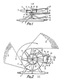
- Fig 1 diagrammatically illustrates a part of a device for spreading granular and/or powdery material, in paticular fertilizer.
- Fig 2 is a top view of fig 1.
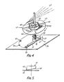
- Fig 3 is a diagrammatic section of a part of a further embodiment of a device according to the invention.
- Fig 4 is a perspective, diagrammatic view of some of the parts of the device illustrated in fig 3.
- Fig 5 diagrammatically illustrates a further possible embodiment of a metering means.
- Figs 1 and 2 illustrate a part of a device for spreading granular and/or powdery material, in particular a fertilizer spreader, comprising a
frame 1 which can be coupled to a tractor or the like. - The
frame 1 supports agearbox 2, in which ashaft 3 extending horizontally in front of the gearbox is journalled. Theshaft 3 can be coupled to the power take-off of a tractor or the like by means of an intermediate shaft in a manner known by itself. - A shaft 4 accommodated with one end in the
gearbox 2 and being at least substantially vertical during normal operation supports aspreading means 5, which may be constructed in a usual manner of adisc 6 and blades 7 fixed to the disc. The construction is thereby such that during operation the spreading means can be rotated about an axis ofrotation 8 formed by the centre line of the shaft 4 and being at least substantially vertical. - Resting on the spreading
means 5 is aring 9 concentrically surrounding the shaft 4. Thering 9 is fixed, by means of afew spokes 10, to abush 11 being freely rotatable about the shaft 4. In thering 10 there is provided ahole 12 forming a discharge opening. - Above the
ring 9 there will be arranged, in a usual manner, a hopper or container supported by theframe 1, containing the material to be spread. Said material can flow from said hopper or container into the interior of thering 9 and from the interior of thering 9 operating as a metering means, through the discharge opening 12, on thedisc 6. Furthermore a closing means, not shown, may be provided by means of which the size of the discharge opening can be varied and possibly closed altogether. - The construction of a fertilizer spreader described hereinabove is generally known and usual.
- The device is furthermore provided with an arm 13 extending radially outwardly from the shaft 4, said arm being pivotable about the shaft 4 as indicated by means of the double arrow A (fig 2) and being fixable in chosen positions.
- To the end of the shaft 4 remote from the arm 13 there is fixed a
bush 14 in which avertical shaft 15 protruding above thebush 14 is journalled freely rotatably. To theshaft 15 there is fixed apulley 16 which is coupled, by means of abelt 17, to apulley 18 fixed to the shaft 4. - To the upper end of the
shaft 15 there is fixed anarm 19 extending perpendicularly to saidshaft 15. In thearm 19 there is provided aslotted hole 20. Accommodated in theslotted hole 20 is the end of apivot pin 21 extending parallel to theshaft 15, said pin being movable, as indicated by means of the double arrow B, in theslotted hole 20 in a direction towards theshaft 15 and in a direction away from theshaft 15 and being fixable in the slottedhole 20 in any desired position. The end of the connectingrod 22 remote from thepivot pin 21 is coupled to thering 9 forming a metering means by means of apivot pin 23 extending paralllel to said pivot pin. - During operation the device will be moved in a direction according to arrow C, whilst the spreading
means 5 will thereby be rotated in the direction according to arrow D, which will also cause rotation of thepulley 16 in the direction according to arrow E. It will be apparent that by transferring said rotation in the direction according to arrow E of thepulley 16 to thering 9 via the crank-connecting rod mechanism formed by thearm 19 and the connectingrod 22 saidring 9 will be put into a reciprocating movement about the axis ofrotation 8. Consequently also the positon of the discharge opening 12 and therewith the position where the material to be spread is delivered to the spreadingmeans 5 will move reciprocatingly about the axis ofrotation 8. - In a first extreme position of the reciprocating movement of the discharge opening 12 the material is e.g. delivered to the spreading means in such a manner that said material is spread over the sector S illustrated in fig 2, whilst in the other extreme position of the discharge opening the material delivered will be spread over the sector Sʹ illustrated in fig 2. However, because the discharge opening 12 moves to and fro between said two extreme positions also the area located between the two sectors S and Sʹ will be strewn over with material. As a result of the comparatively small angle over which a sector S extends, however, it will be possible to have very even spreading in such a sector and therewith also over the entire area covered during operation.
- Furthermore it will be apparent that by adjusting the arm 13 about the axis of
rotation 8 the position of the strip of land strewn over with material during operation relative to the longitudinal axis of the device can also be altered, so that in using the construction according to the invention it will also be possible to spread both behind and beside the device. - By adjusting the
pivot point 21 along thearm 19 it will be possible to regulate the length of the stroke ofring 9 about axis ofrotation 8 and therewith the entire spreading width. - Fig 3 and 4 diagrammatically illustrate an embodiment of a spreader, in particular a fertilizer spreader, whereby during operation the spreading means is rotatable about an axis of rotation including an angle with the vertical.
- As already explained hereinabove such a construction is used e.g. to make it possible to spread the fertilizer over high standing crops. If the fertilizer is flung from the spreading disc over a comparatively large circumferential angle for obtaining a sufficiently large spreading area, there will be the disadvantage that e.g. near the centre of said angle over which the material is flung the material will be flung steeper upwards than near the ends of said angle over which the material is flung. It will be apparent that this has a very disadvantageous influence on an even spreading of the material. As will be more fully explained hereinafter this can be avoided by using the construction according to the invention.
- As is illustrated in fig 3 the device comprises a
frame 24, accommodating abush 25 which supports a lower end of avertical shaft 26 by means of abearing 27. To the end of theshaft 26 protruding above the bush there is fixed anarm 28 extending perpendicularly to theshaft 26. To the free end of thearm 28 there is fixed apin 29. By means of thepin 29 there is pivotally connected with thearm 28 the piston rod of asetting cilinder 31. The end of thepiston rod 30 remote from thesetting cilinder 31 is connected to theframe 24 diagrammatically illustrated in fig 4 by means of apin 32. - For connecting the
pin 32 to theframe 24several holes 33 are provided in the frame, said holes being located on a circular arc extending concentrically about the centre line of theshaft 26. - Above the
arm 28 theshaft 26 is surrounded by a bush 34, which is supported freely rotatably about theshaft 26 by means ofbearings 35. The bush 34 is provided with apulley 36 at its lower end and with agear wheel 37 at its upper end. - The part of the
shaft 26 protruding above the bush 34 is provided with a thickening 38 having a circular section whose centre line 39 includes an angle with thecentre line 40 of theshaft 26, being at least substantially vertical during normal operation. On the shaft shaped thickening 38 aboss 42 of a spreadingmeans 43 is rotatable by means of bearings 41. Also in this embodiment the spreadingmeans 43 comprises a disc shapedmeans 45 and throwingscoops 46 fixed to said disc shaped means. The spreadingmeans 43 is furthermore provided with agear wheel 47 extending concentrically about the centre line 39 forming an axis of rotation for the spreading means, said gear wheel engaging thegear wheel 37 in the manner illustrated in fig 3. - To a thickened
upper end 48 of theshaft part 38 there is fixed a ring 44, which is connected, by means of afew spokes 49, to a supportingring 50 extending concentrically about the centre line 39. Abearing ring 51 is rotatable about said supportingring 50 and fixable in a desired position by means of locking means not shown. To the bottom end of thebearing ring 51 there is fixed aring 52 operating as a metering means and located under the supportingring 50 and in the extension of said supporting ring. In thering 52 there is provided ahole 53 acting as a discharge opening. There may be provided means, not shown, for regulating the size of the hole and/or closing the hole. - Furthermore the device is provided with a reservoir 54 supported by the frame, under whose open lower end there is arranged a
bottom plate 56 provided withopenings 55. Theopenings 55 in said bottom plate can be closed by means of amovable closing plate 57 located under the bottom plate, said closing plate also being provided withopenings 58. - To the upper end of the
shaft 26 located near the lower end of the reservoir 54 there is furthermore fixed a stirring means 59. - For rotating the spreading means 43 about its axis of rotation 39 the bush 34 with the
gear wheel 37 connected thereto is rotated via a belt transmission, not shown, driven in a usual manner from e.g. the power take-off of a tractor supporting the device, thepulley 36 forming part of said belt transmission. - During operation the fertilizer can flow in a usual manner from the reservoir through the
openings ring 52 acting as a metering means and be supplied from said ring through thedischarge opening 53 to thescoops 46 of the spreading disc, as is usual with fertilizer spreaders and the like. - According to the invention, however, the
shaft 26 can now be pivoted to and fro by means of the settingcilinder 31 during operation, as is indicated by means of the arrow G in fig 4. It will be apparent that thereby theshaft part 38 and with it also the spreadingmeans 43 and the metering means 52 are pivoted about thecentre line 40 of theshaft 26. During said pivoting of the metering means 52 and the spreading means 43 the position of the discharge opening relative to e.g. the highest point of the disc shaped means of the spreading means remains unchanged, therefore. - By using the construction according to the invention it is possible to achieve, therefore, that on the one hand the material is flung from the spreading means of the device over a comparatively small circumferential angle, so that said material covers a comparatively small sector Sʺ as indicated in fig 4, which advantageously influences an even spreading, as all the material moves obliquely upwardly at substantially the same angle, whilst on the other hand said sector Sʺ is pivoted to and fro about the
centre line 40 of theshaft 26 during operation, so that it is still possible to cover a wide strip of land. - By choosing the connecting
point 33 at which the settingcilinder 31 is coupled to theframe 24 it is possible to choose the position of the strip of land strewn over during operation, e.g. beside or behind the device. - Preferably also adjusting means, not shown, are provided by means of which the
ring 52 can be adjusted about the axis of rotation 39 relative to the spreading means 43 in order to influence therewith the location where the material is delivered through the discharge opening to the spreadingmeans 43. Because of that it will be possible to influence the direction in which the material is flung from the spreading means and that gradually increasing from a substantially horizontal direction to a direction aimed strongly obliquely upwardly. - Means may also be provided for regulating the stroke of the setting
cilinder 31 for influencing the working width of the device. - Of course many variants of the embodiments described hereinabove will be possible within the spirit and scope of the invention. Besides e.g. the crank-connecting rod mechanism illustrated in figs 1 and 2 or the setting cilinder for effecting a reciprocating movent of the metering means illustrated in fig 4 also other driving mechanisms, e.g. eccentric mechanisms or the like may be used. Driving may thereby take place mechanically, hydraulically or electrically. Also many variants of the construction of the metering means will be possible.
- Thus fig 5 diagrammatically illustrates a metering means 61 above a spreading
means 60. Said metering means 61 is formed by a hopper, open at its upper side and having a bottom 63 extending obliquely downwardly in the direction of aspout 62 at its bottom side. Here the bottom 63 carries the material, therefore, and said material can only be discharged via thespout 62.
Claims (11)
Priority Applications (1)
| Application Number | Priority Date | Filing Date | Title |
|---|---|---|---|
| AT87200789T ATE48734T1 (en) | 1986-05-06 | 1987-04-27 | SPREADER FOR GRAINY AND/OR POWDERY MATERIAL. |
Applications Claiming Priority (2)
| Application Number | Priority Date | Filing Date | Title |
|---|---|---|---|
| NL8601148 | 1986-05-06 | ||
| NL8601148A NL8601148A (en) | 1986-05-06 | 1986-05-06 | DEVICE FOR SPREADING GRAIN AND / OR POWDERED MATERIAL. |
Publications (2)
| Publication Number | Publication Date |
|---|---|
| EP0244906A1 true EP0244906A1 (en) | 1987-11-11 |
| EP0244906B1 EP0244906B1 (en) | 1989-12-20 |
Family
ID=19847976
Family Applications (1)
| Application Number | Title | Priority Date | Filing Date |
|---|---|---|---|
| EP87200789A Expired EP0244906B1 (en) | 1986-05-06 | 1987-04-27 | Device for spreading granular and/or powdery material |
Country Status (10)
| Country | Link |
|---|---|
| US (1) | US4776519A (en) |
| EP (1) | EP0244906B1 (en) |
| AT (1) | ATE48734T1 (en) |
| CA (1) | CA1287363C (en) |
| DE (1) | DE3761177D1 (en) |
| DK (1) | DK168184B1 (en) |
| ES (1) | ES2012797B3 (en) |
| IE (1) | IE59929B1 (en) |
| NL (1) | NL8601148A (en) |
| SU (1) | SU1575927A3 (en) |
Cited By (1)
| Publication number | Priority date | Publication date | Assignee | Title |
|---|---|---|---|---|
| EP0598494A2 (en) * | 1992-10-20 | 1994-05-25 | Peter William Allen | Apparatus and method for dispensing flowable material |
Families Citing this family (5)
| Publication number | Priority date | Publication date | Assignee | Title |
|---|---|---|---|---|
| US5735319A (en) * | 1995-10-03 | 1998-04-07 | Mcnamara; John O. | Dispersing apparatus and method |
| US6715703B2 (en) * | 2002-03-05 | 2004-04-06 | The Louis Berkman Company | Spreader |
| US7530509B2 (en) * | 2006-07-17 | 2009-05-12 | Ricky L. Gaughan | Manure-grinding fertilizer spreader |
| US7762290B2 (en) * | 2008-11-06 | 2010-07-27 | Poet Research, Inc. | System for loading particulate matter into a transport container |
| US10203236B2 (en) | 2014-09-22 | 2019-02-12 | Rotacon Engineering Limited | Metering of granular materials including seeds |
Citations (5)
| Publication number | Priority date | Publication date | Assignee | Title |
|---|---|---|---|---|
| FR647268A (en) * | 1927-11-05 | 1928-11-22 | Machine for spreading artificial and similar fertilizers | |
| FR1134277A (en) * | 1955-10-20 | 1957-04-09 | Advanced distributor for the spreading mechanism of chemical fertilizers, seeds and other products | |
| FR1431726A (en) * | 1964-12-31 | 1966-03-18 | Mini Ind Constructillor | Machine for spraying fertilizers and other powdery or granular materials |
| DE1582067A1 (en) * | 1967-01-21 | 1970-12-10 | Eugen Popp | Centrifugal fertilizer spreader with semicircular parabolic distributor and quantity control |
| DE2031557A1 (en) * | 1970-06-26 | 1971-12-30 | Fahrzeug- Und Landmaschinenfabrik Sebastian Unsinn, 8890 Aichach | Device for spreading granular material |
Family Cites Families (13)
| Publication number | Priority date | Publication date | Assignee | Title |
|---|---|---|---|---|
| US2489171A (en) * | 1945-10-31 | 1949-11-22 | Fmc Corp | Spreader |
| US2519243A (en) * | 1946-01-17 | 1950-08-15 | Milford Davis | Fertilizer spreader |
| US2587678A (en) * | 1948-07-24 | 1952-03-04 | Sears Roebuck & Co | Lime spreader |
| US2723860A (en) * | 1952-06-03 | 1955-11-15 | Charles E Weeks | Tractor mounted broadcast seeder |
| US3129846A (en) * | 1959-10-26 | 1964-04-21 | Lely Nv C Van Der | Implements for spreading powdered or granular materials |
| US3157403A (en) * | 1960-08-26 | 1964-11-17 | Lely Nv C Van Der | Agricultural implements |
| US3401889A (en) * | 1965-10-21 | 1968-09-17 | Parker Feeders Inc | Combination gravity bed reservoir and hopper-plus-scatterer |
| US3618824A (en) * | 1968-08-30 | 1971-11-09 | Sperry Rand Corp | Material spreader |
| US3899138A (en) * | 1969-01-17 | 1975-08-12 | Der Lely Ary Van | Spreading implements |
| US3964681A (en) * | 1975-09-04 | 1976-06-22 | Herd Elmer R | Agricultural broadcasting apparatus |
| NL7605530A (en) * | 1976-05-24 | 1977-11-28 | Lely Nv C Van Der | DEVICE FOR DISTRIBUTION OF GRAIN AND / OR POWDER MATERIAL. |
| WO1983000794A1 (en) * | 1981-09-07 | 1983-03-17 | Van Der Lely, Cornelis | A device for spreading granular and/or powdery material |
| NL8502598A (en) * | 1985-09-23 | 1986-01-02 | Lely Nv C Van Der | Agricultural granular material spreading machine - has hopper supporting arms on vertical frame section also carrying drive motor |
-
1986
- 1986-05-06 NL NL8601148A patent/NL8601148A/en not_active Application Discontinuation
-
1987
- 1987-04-27 AT AT87200789T patent/ATE48734T1/en not_active IP Right Cessation
- 1987-04-27 ES ES87200789T patent/ES2012797B3/en not_active Expired - Lifetime
- 1987-04-27 DE DE8787200789T patent/DE3761177D1/en not_active Expired - Fee Related
- 1987-04-27 EP EP87200789A patent/EP0244906B1/en not_active Expired
- 1987-04-29 US US07/043,952 patent/US4776519A/en not_active Expired - Fee Related
- 1987-04-30 CA CA000536129A patent/CA1287363C/en not_active Expired - Lifetime
- 1987-05-05 DK DK228887A patent/DK168184B1/en active
- 1987-05-05 SU SU874202542A patent/SU1575927A3/en active
- 1987-05-11 IE IE116187A patent/IE59929B1/en not_active IP Right Cessation
Patent Citations (5)
| Publication number | Priority date | Publication date | Assignee | Title |
|---|---|---|---|---|
| FR647268A (en) * | 1927-11-05 | 1928-11-22 | Machine for spreading artificial and similar fertilizers | |
| FR1134277A (en) * | 1955-10-20 | 1957-04-09 | Advanced distributor for the spreading mechanism of chemical fertilizers, seeds and other products | |
| FR1431726A (en) * | 1964-12-31 | 1966-03-18 | Mini Ind Constructillor | Machine for spraying fertilizers and other powdery or granular materials |
| DE1582067A1 (en) * | 1967-01-21 | 1970-12-10 | Eugen Popp | Centrifugal fertilizer spreader with semicircular parabolic distributor and quantity control |
| DE2031557A1 (en) * | 1970-06-26 | 1971-12-30 | Fahrzeug- Und Landmaschinenfabrik Sebastian Unsinn, 8890 Aichach | Device for spreading granular material |
Cited By (3)
| Publication number | Priority date | Publication date | Assignee | Title |
|---|---|---|---|---|
| EP0598494A2 (en) * | 1992-10-20 | 1994-05-25 | Peter William Allen | Apparatus and method for dispensing flowable material |
| EP0598494A3 (en) * | 1992-10-20 | 1994-06-15 | Peter William Allen | Apparatus and method for dispensing flowable material. |
| US5732652A (en) * | 1992-10-20 | 1998-03-31 | Allen; Peter William | Apparatus and method for dispensing flowable material |
Also Published As
| Publication number | Publication date |
|---|---|
| IE59929B1 (en) | 1994-05-04 |
| IE871161L (en) | 1987-11-06 |
| EP0244906B1 (en) | 1989-12-20 |
| DK228887A (en) | 1987-11-07 |
| ES2012797B3 (en) | 1990-04-16 |
| US4776519A (en) | 1988-10-11 |
| DK168184B1 (en) | 1994-02-28 |
| DE3761177D1 (en) | 1990-01-25 |
| DK228887D0 (en) | 1987-05-05 |
| CA1287363C (en) | 1991-08-06 |
| ATE48734T1 (en) | 1990-01-15 |
| NL8601148A (en) | 1987-12-01 |
| SU1575927A3 (en) | 1990-06-30 |
Similar Documents
| Publication | Publication Date | Title |
|---|---|---|
| US4597531A (en) | Material spreader | |
| EP0053419B1 (en) | A spreader | |
| US4867381A (en) | Broadcast spreader for pulverized materials | |
| US4166581A (en) | Spreader for particulate material | |
| US3586246A (en) | Spreading apparatus | |
| EP0244906B1 (en) | Device for spreading granular and/or powdery material | |
| US2514962A (en) | Portable spreader device | |
| CN110332785A (en) | A kind of tanning device for crops | |
| US4350303A (en) | Device for spreading material | |
| CN108848711A (en) | A kind of gardens soil uniform of application equipment | |
| DE102005015228A1 (en) | Centrifuge spreader for spreading agricultural and local grit e.g. mineral fertilizer, has funnel-shaped lower part with V-shaped profile having circular section, whose curvature radius coincides with operating cycle of agitator fingers | |
| US6116526A (en) | Implement for spreading granular and/or pulverulent material | |
| CN209497842U (en) | A kind of agricultural farming device | |
| CN215403752U (en) | Turning and throwing device | |
| US4316581A (en) | Spreader suitable for spreading granular and/or powdery material | |
| EP0511714A2 (en) | Spreader | |
| DE102007021442B4 (en) | Centrifugal fertilizer spreader with remote-adjustable centrifugal discs | |
| DE102004004711A1 (en) | Double disc spreader for distributing spreading material, especially fertilizer | |
| EP0088105A1 (en) | Device for spreading granular and/or powdery material. | |
| EP0853871B1 (en) | Centrifugal spreader | |
| GB2154112A (en) | A device for spreading particulate material | |
| EP0238153B1 (en) | A spreader for spreading granular and/or powdery matrial | |
| EP0784917B1 (en) | An implement for spreading granular and/or pulverulent material | |
| KR20000011403U (en) | Compost spraying device | |
| AU752653B2 (en) | Rotary plant mowing apparatus |
Legal Events
| Date | Code | Title | Description |
|---|---|---|---|
| PUAI | Public reference made under article 153(3) epc to a published international application that has entered the european phase |
Free format text: ORIGINAL CODE: 0009012 |
|
| AK | Designated contracting states |
Kind code of ref document: A1 Designated state(s): AT BE CH DE ES FR GB GR IT LI LU NL SE |
|
| 17P | Request for examination filed |
Effective date: 19871029 |
|
| 17Q | First examination report despatched |
Effective date: 19890512 |
|
| GRAA | (expected) grant |
Free format text: ORIGINAL CODE: 0009210 |
|
| AK | Designated contracting states |
Kind code of ref document: B1 Designated state(s): AT BE CH DE ES FR GB GR IT LI LU NL SE |
|
| PG25 | Lapsed in a contracting state [announced via postgrant information from national office to epo] |
Ref country code: IT Free format text: LAPSE BECAUSE OF FAILURE TO SUBMIT A TRANSLATION OF THE DESCRIPTION OR TO PAY THE FEE WITHIN THE PRESCRIBED TIME-LIMIT;WARNING: LAPSES OF ITALIAN PATENTS WITH EFFECTIVE DATE BEFORE 2007 MAY HAVE OCCURRED AT ANY TIME BEFORE 2007. THE CORRECT EFFECTIVE DATE MAY BE DIFFERENT FROM THE ONE RECORDED. Effective date: 19891220 Ref country code: BE Effective date: 19891220 Ref country code: CH Effective date: 19891220 Ref country code: GR Free format text: LAPSE BECAUSE OF FAILURE TO SUBMIT A TRANSLATION OF THE DESCRIPTION OR TO PAY THE FEE WITHIN THE PRESCRIBED TIME-LIMIT Effective date: 19891220 Ref country code: LI Effective date: 19891220 |
|
| REF | Corresponds to: |
Ref document number: 48734 Country of ref document: AT Date of ref document: 19900115 Kind code of ref document: T |
|
| REF | Corresponds to: |
Ref document number: 3761177 Country of ref document: DE Date of ref document: 19900125 |
|
| ET | Fr: translation filed | ||
| REG | Reference to a national code |
Ref country code: CH Ref legal event code: PL |
|
| PG25 | Lapsed in a contracting state [announced via postgrant information from national office to epo] |
Ref country code: LU Free format text: LAPSE BECAUSE OF NON-PAYMENT OF DUE FEES Effective date: 19900430 |
|
| PLBE | No opposition filed within time limit |
Free format text: ORIGINAL CODE: 0009261 |
|
| STAA | Information on the status of an ep patent application or granted ep patent |
Free format text: STATUS: NO OPPOSITION FILED WITHIN TIME LIMIT |
|
| 26N | No opposition filed | ||
| PGFP | Annual fee paid to national office [announced via postgrant information from national office to epo] |
Ref country code: ES Payment date: 19940211 Year of fee payment: 8 Ref country code: GB Payment date: 19940211 Year of fee payment: 8 |
|
| PGFP | Annual fee paid to national office [announced via postgrant information from national office to epo] |
Ref country code: AT Payment date: 19940411 Year of fee payment: 8 |
|
| PGFP | Annual fee paid to national office [announced via postgrant information from national office to epo] |
Ref country code: SE Payment date: 19940426 Year of fee payment: 8 |
|
| PGFP | Annual fee paid to national office [announced via postgrant information from national office to epo] |
Ref country code: FR Payment date: 19940428 Year of fee payment: 8 |
|
| PGFP | Annual fee paid to national office [announced via postgrant information from national office to epo] |
Ref country code: NL Payment date: 19940430 Year of fee payment: 8 |
|
| PGFP | Annual fee paid to national office [announced via postgrant information from national office to epo] |
Ref country code: DE Payment date: 19940615 Year of fee payment: 8 |
|
| EAL | Se: european patent in force in sweden |
Ref document number: 87200789.3 |
|
| PG25 | Lapsed in a contracting state [announced via postgrant information from national office to epo] |
Ref country code: AT Effective date: 19950427 Ref country code: GB Effective date: 19950427 |
|
| PG25 | Lapsed in a contracting state [announced via postgrant information from national office to epo] |
Ref country code: ES Free format text: LAPSE BECAUSE OF NON-PAYMENT OF DUE FEES Effective date: 19950428 Ref country code: SE Effective date: 19950428 |
|
| PG25 | Lapsed in a contracting state [announced via postgrant information from national office to epo] |
Ref country code: NL Effective date: 19951101 |
|
| PG25 | Lapsed in a contracting state [announced via postgrant information from national office to epo] |
Ref country code: FR Effective date: 19951229 |
|
| NLV4 | Nl: lapsed or anulled due to non-payment of the annual fee |
Effective date: 19951101 |
|
| GBPC | Gb: european patent ceased through non-payment of renewal fee |
Effective date: 19950427 |
|
| PG25 | Lapsed in a contracting state [announced via postgrant information from national office to epo] |
Ref country code: DE Effective date: 19960103 |
|
| EUG | Se: european patent has lapsed |
Ref document number: 87200789.3 |
|
| REG | Reference to a national code |
Ref country code: FR Ref legal event code: ST |
|
| REG | Reference to a national code |
Ref country code: ES Ref legal event code: FD2A Effective date: 19990201 |