EP0244676A2 - Method for improving system operation by programming micro word cycle length - Google Patents
Method for improving system operation by programming micro word cycle length Download PDFInfo
- Publication number
- EP0244676A2 EP0244676A2 EP87105554A EP87105554A EP0244676A2 EP 0244676 A2 EP0244676 A2 EP 0244676A2 EP 87105554 A EP87105554 A EP 87105554A EP 87105554 A EP87105554 A EP 87105554A EP 0244676 A2 EP0244676 A2 EP 0244676A2
- Authority
- EP
- European Patent Office
- Prior art keywords
- vector
- accordance
- control word
- control
- execution
- Prior art date
- Legal status (The legal status is an assumption and is not a legal conclusion. Google has not performed a legal analysis and makes no representation as to the accuracy of the status listed.)
- Granted
Links
Images


Classifications
-
- G—PHYSICS
- G06—COMPUTING; CALCULATING OR COUNTING
- G06F—ELECTRIC DIGITAL DATA PROCESSING
- G06F9/00—Arrangements for program control, e.g. control units
- G06F9/06—Arrangements for program control, e.g. control units using stored programs, i.e. using an internal store of processing equipment to receive or retain programs
- G06F9/22—Microcontrol or microprogram arrangements
- G06F9/223—Execution means for microinstructions irrespective of the microinstruction function, e.g. decoding of microinstructions and nanoinstructions; timing of microinstructions; programmable logic arrays; delays and fan-out problems
Definitions
- the present invention relates to a method for optimizing computer system performance and, in particular, to optimizing computer system performance by programming micro word cycle length.
- a vector processor which typically includes a plurality of vector registers, each vector register storing a vector having a plurality of vector elements.
- a pipeline processing unit is connected to a selector associated with the vector registers for receiving corresponding elements of a first vector from a first vector register and utilizing the corresponding elements to perform an arithmetic operation on the corresponding elements of a second vector stored in a second vector register.
- the results of the arithmetic operation are stored in corresponding locations of one of the vector registers or in corresponding locations of a third vector register.
- the vectors include 128 elements, for example, 128 operations must be performed in sequence.
- the time required to complete operations on all 128 elements of the vector is a function of the cycle time per operation of the pipeline unit as it operates on each of the corresponding elements.
- Each operation can require a unique predetermined time period in which to execute.
- each secondary device has certain characteristics. So the cycle length value is a function both of the vector processor operating characteristics and of the secondary device.
- European patent application 84109081.4 gives an example of a vector processor.
- the micro instructions also include a plurality of clock codes for controlling the operation of a programmable clock, a plurality of qualifier selection codes for selecting qualifiers and serving as primary address codes for addressing the read only memory of the microprocessor and a plurality of secondary address codes for addressing the read only memory of the microprocessor.
- the micro words can be programmed for shift register timing.
- United States patent number 4,439,829 issued to Tsiang discloses a data processing machine having cache memory and a management system therefor.
- the length of a micro instruction cycle of a central processor varies according to the nature of the micro instruction.
- control signals of the micro instruction controlling central processor are input therefrom to a decoder and counter.
- a hardware decoder is therefore required for operation of the Tsiang system.
- delay time or execution time could be integrally carried with the micro word instruction corresponding thereto.
- Timing or counting mechanism to generate a signal to indicate when a predetermined time interval has expired.
- a control word is provided having a control portion for operational instructions and a programmable timing portion.
- the programmable timing portion includes a value representative of the sum of execution time and inter-execution delay time.
- a counter is provided for receiving the value representative of the execution and inter-execution times. The counter is capable of generating a signal to indicate an end of decrementing operation.
- the operational instructions are executed simultaneously with the processing of the time value in the counter so that a subsequent instruction is executed only when an end of operation signal is received from the counter.
- FIGURE 1 a pipeline vector processor 10 is illustrated.
- a plurality of vector registers 12 VR0 through VR15 are shown, each register storing 128 vector elements 13 (elements 0 through 127).
- an element 13 comprises a four byte binary word.
- a selector 14 is connected to each of the vector registers 12 for selecting corresponding elements 13 from the vector registers 12 and for gating the selected elements 13 through to a pipeline processing unit 16.
- the pipeline processing unit 16 is connected to the selector 14 for receiving the corresponding elements 13 and for performing selected operations thereon, such as arithmetic operations.
- the processing unit 16 may receive element 0 from vector register VR0 and corresponding element 0 from vector register VR15 and may perform the following arithmetic operation on said elements: VR0 + VR15 ⁇ VR3.
- each bit of element 0 in VR0 is added to each respective bit of element 0 in VR15.
- the resultant sum is stored in the element 0 position of vector register VR3.
- a result register 18 is connected to the pipeline processing unit 16 for storing the resultant sum received therefrom.
- the resultant register 18 is connected to each of the vector registers 12 via a select gate 20 for transferring the resultant sum, in the aforementioned example, from the result register 18 to the appropriate vector register, in this case VR3.
- a first element 13 is selected from register VR0 and a corresponding element 13 is selected from register VR15.
- the elements 13 are added.
- Second elements 13 are selected from each of registers VR0 and VR15 respectively and are also added.
- Each of the 128 elements 13 must be selected from registers VR0 and VR15 and added together, in sequence, in order to complete processing.
- the time required to complete the processing of the vectors stored in vector registers VR0 and VR15 is a function of the number of elements 13 per vector and the cycle time required to process a set of corresponding elements 13 per vector.
- the overall performance of a vector processor can thus be improved by decreasing the time required to process every pair of vectors stored in a set of vector registers 12.
- each of the vector registers VR0 and VR15 are subdivided into a plurality of smaller registers 12a, each smaller register 12a containing four elements.
- a corresponding plurality of element processors 21 are connected to the plurality of smaller registers 12a for performing processing (arithmetic) operations on the corresponding elements of the vectors stored in the registers 12.
- Each of the element processors 21 performs processing operations on four corresponding elements of the vector registers 12. The results of the processing operation are simultaneously produced by each element processor 21, in parallel, and may be stored in corresponding locations of any one of the vector registers VR0 through VR15.
- a processor interface adaptor (PIA) 22 is connected to all of the element processors 21 for transmitting address, data and command information thereto.
- the actual connection of the PIA 22 to each of the element processors 0-31 is illustrated in FIGURE 3 of the drawings, as hereinbelow described.
- An instruction processing unit (IPU) 24 is connected to the PIA 22 for transmitting vector instructions thereto.
- a main memory or storage 26 is connected to the PIA 22 for transmitting data information and address control information to the PIA 22 in response to its request for such data.
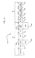
- FIGURE 3 the separate connections of the PIA 22 to each of the element processors 21 (processor 0 through processor 31) is illustrated.
- the PIA 22 is directly connected to element processors 0, 8, 16 and 24.
- Element processor 0 is in turn serially connected to element processors 1 through 7, processor 8 to processors 9 through 15, processor 16 to processors 17 through 23 and processor 24 to processors 25 through 31.
- the PIA 22 includes a vector instruction register (VIR) 22a connected to the IPU 24 for receiving a vector instruction therefrom and for temporarily storing the vector instruction.
- a vector data register (VDR) 22b is connected to storage 26 and to the IPU 24 for receiving data therefrom and for temporarily storing the data.
- a vector status register (VSR) 22c is also connected to the storage 26 and to the IPU 24 for receiving address control information from storage and for temporarily storing the information.
- a pico control store 22d is connected to the VIR 22a for decoding the vector instruction stored in the VIR 22a and for selecting a pico control routine residing in the store 22d.
- a command register 22e is connected to the pico control store 22d and to the element processors 21 via a command bus for driving the element processors 21.
- a counter 22i Also connected to the pico control store 22d is a counter 22i having a timer initiation signal (TIS) line for loading a value generated by the store 22d and an end of operation signal (EOS) line for transmitting an end of operation signal to the store 22d, as hereinbelow described.
- TIS timer initiation signal
- EOS end of operation signal
- a bus control 22f is connected to the VDR 22b for receiving data from the VDR 22b and for transmitting the data to the element processors 21 via a data bus.
- the bus control 22f can also steer data from one element processor 21 to another.
- the IPU 24 instructs the PIA 22 to load specific data into vector registers VR0 through VR15.
- the IPU 24 transmits a LOAD instruction to the PIA 22.
- the LOAD instruction is temporarily stored in the VIR 22a.
- the data to be loaded into the vector registers 12 resides in storage 26.
- the PIA 22 receives the LOAD instruction, it retrieves specific data from storage 26 and loads said data into the VDR 22b.
- the data stored in the VDR 22b is transmitted for storage in the selected processors 21 via the bus control 22f and associated data bus.
- the command information stored in the pico control store 22d and selected by the decoded LOAD instruction is transmitted to the selected processors 21 via command register 22e and associated command bus.
- the selected command information causes the data stored in the selected processors 21 to be loaded into elements of the smaller registers 12a, the elements being identified by the address information generated by the address control 22h.
- the IPU 24 instructs the PIA 22 to perform an ADD operation wherein the vector stored in vector register VR0 is to be added to the vector stored in vector register VR15, the result now to be stored in vector register VR15, replacing its original contents.
- the IPU 24 transmits the ADD instruction to the PIA 22.
- the ADD instruction is temporarily stored in the VIR 22a.
- particular command information residing in the store 22d is selected.
- the IPU 24 retrieves specific data from storage 26 representative of the addresses of the elements 13 in the smaller registers 12a undergoing the ADD operation and the address of the selected processors 21 which will perform the ADD operation. As a result, address information is generated by the address control 22h.
- the address information is transmitted to the selected processors 21 via the bus control 22g and associated address bus.
- the selected command information selected from the pico control store 22d instructs the selected processors 21 to retrieve the selected elements 13 of associated smaller registers 12a corresponding to vector registers VR0 and VR15.
- the selected command information causes the selected processors 21 to execute the ADD instruction.
- elements 0 through 3 associated with the vectors stored in vector registers VR0 and VR15 are received by element processor number 0.
- Element processor 0 adds the corresponding elements together and, in accordance with the selected command information, stores the results of the addition operation in the corresponding locations of vector register VR15. That is, element 0 of vector register VR0 is added to element 0 of vector register VR15 and the sum is now stored in the element 0 location of vector register VR15.
- the remaining elements 13 of the vectors, stored in vector registers VR0 and VR15, are processed simultaneously by element processors 2 through 31 in groups of four elements 13 each.
- the vector arithmetic operation performed on all the vectors stored in vector registers VR0 and VR15 is completed in the time required to process only four elements of the vector.
- control word 30 in accordance with the present invention.
- the control word 30 resides in the pico control store 22d (FIGURE 4).
- the control word 30 has 32 bits and is divided into two portions.
- the first portion, identified by reference numeral 54, contains operational instructions.
- the second portion 56 contains control and timing information.
- Bits 0-3 are used to identify a command 32.
- Bits 4-5 indicate a function 34.
- Bits 6-7 indicate a result 36a or a column 36b depending upon the command 32 that is used in the control word 30.
- Bits 8-11 indicate the identity of a data source (SRC) 38.
- SRC data source
- the SP mode operates on one element; the BC mode operates on n elements, where n is the number of processors; and the BA mode operates as a sequence of BC operations in a pipelined fashion.
- the interprocessor (IP) mode provides for one processor to communicate by passing an operand to another processor for execution therein.
- Bits 14-15 represent IPU branch conditions 42a, while bits 14-16 can be used, depending upon the command 32 specified in bits 0-3, to identify a row 42b. Thus, depending on the control word command 32, bits 6-7 and 14-16 are interpreted in one of two ways, the second of which identifies columns and rows, respectively.
- Bit 17 is an address update bit 44.
- Bit 18 is an end of operation bit 46. Bit 17 and 18 are used for internal control in the PIA 22.
- Bits 19-23 represent the programmable micro word cycle time 48. This is the value that indicates the number of cycles required to perform a specified command 32 by a given secondary or peripheral device, such as an array of element processors 21 (FIGURE 3). The value stored in bits 19-23 is normally preloaded by a programmer. This value is the sum of execution time and inter-execution delay time.
- Bits 24-28 represent the address for the next word 50. Thus, words need not be executed sequentially.
- Bits 29-31 represent a branch condition 52 based upon the outcome of execution of the current command 32.
- the operational instruction portion 54 of the control word 30 is transmitted to, and used by, any one of the element processors 21 (FIGURE 3). Bits 17 and 18, representing the address update bit 44 and end of operation bit 46, and the rest of the control portion 56 of the control word 30 remain in, and are used by, the PIA 22.
- the counter 22i connected to the pico control store 22d processes values representative of the number of cycles 48 in the control word 30.
- the operational instruction portion 54 thereof is transferred to the element processors 21 via the command register 22e and associated command bus at the same time that the control and timing portion 56 is used within the PIA 22.
- the pico control store 22d transfers the value 48 residing in the number of cycles bits 19-23 to the counter 22i over the TIS line.
- the counter 22i begins a decrementing operation, as is well known in the art, beginning at the value 48 loaded therein. When the counter 22i decrements to zero, it generates an end of decrementing operation signal and transmits that signal over the EOS line to the pico control store 22d.
- the store 22d is now in a position to begin execution of the next control word 30.
- the next word whose address 50 is also stored in the control word 30, begin execution.
- This next execution is initiated by transferring the operational instruction portion 54 of the control word 30 to the specified element processors 21 via the command register 22e and associated command bus.
- the new value 48 representing another time interval is transferred to the counter 22i over the TIS line for simultaneous decrementing operations, to be terminated when the counter value reaches zero.
- the counter 22i then generates its end of decrementing operation signal and sends that signal over the EOS line to the pico control store 22d.
- the counter 22i When the value 48 in the control word 30 is calculated with care by a programmer, the counter 22i reaches zero and generates an end of decrementing operation signal over the EOS line when or shortly after execution of the operational instruction portion 56 of the control word 30 has been completed. Thus, overall system efficiency is improved due to an improvement of individual operations on the micro word level.
Abstract
Description
- The present invention relates to a method for optimizing computer system performance and, in particular, to optimizing computer system performance by programming micro word cycle length.
- In sophisticated computer systems, especially in larger processors, there is often a need to execute a great number of operations in the shortest possible time. It has been found that as cycle length (i.e., the time required to perform the most simple operation) decreases to the millisecond and even nanosecond range, even a short delay time between executions of operations can become a significant factor in overall system operation. When thousands or millions of operations are performed each second, an inefficient or wasteful segment of time on a cycle level grows to an appreciable degradation of system performance when multiplied by hours, months or years.
- In systems that have a plurality of processors or one or more processors used in conjunction with a plurality of other (e.g., peripheral) devices, it would be helpful to predict the amount of time required to perform certain operations, thus eliminating a requirement for processors to be inactive or non-operational while such operations are performed.
- The prior art is replete with examples of inadequate solutions to the aforementioned problem. Predetermining the amount of delay time for a processor for each operation, for example, can result in estimating too short a time, in which case secondary devices connected to the processor may have insufficient time to complete their respective operations, resulting in malfunctions. In order to allocate enough time for secondary devices to execute their tasks, too much time may be reserved, resulting in occasional or even chronic delay. Obviously, neither of these cases represents optimum performance efficiency.
- The aforementioned problem is especially troublesome in a vector processor, which typically includes a plurality of vector registers, each vector register storing a vector having a plurality of vector elements. A pipeline processing unit is connected to a selector associated with the vector registers for receiving corresponding elements of a first vector from a first vector register and utilizing the corresponding elements to perform an arithmetic operation on the corresponding elements of a second vector stored in a second vector register. The results of the arithmetic operation are stored in corresponding locations of one of the vector registers or in corresponding locations of a third vector register.
- As a result of increasing sophistication of computer systems, the need exists to increase the performance of the vector processor portion of the computer system by decreasing time required to process or perform arithmetic operations on each of the corresponding elements of the plurality of vectors stored in the vector registers.
- If the vectors include 128 elements, for example, 128 operations must be performed in sequence. The time required to complete operations on all 128 elements of the vector is a function of the cycle time per operation of the pipeline unit as it operates on each of the corresponding elements.
- Each operation can require a unique predetermined time period in which to execute. Moreover, each secondary device has certain characteristics. So the cycle length value is a function both of the vector processor operating characteristics and of the secondary device.
- European patent application 84109081.4 gives an example of a vector processor.
- United States patent number 4,456,964 issued to Olander, Jr. et al and United States patent number 4,412,300 issued to Watson et al disclose an electronic calculator that contains micro instructions and codes to perform basic functions of the calculator. The micro instructions include a plurality of coded and non-coded micro instructions for transferring control to an input/output control unit, for controlling the addressing and accessing of a memory unit, and for controlling the operation of two accumulator registers, a program counter register, an extend register and an arithmetic logic unit. The micro instructions also include a plurality of clock codes for controlling the operation of a programmable clock, a plurality of qualifier selection codes for selecting qualifiers and serving as primary address codes for addressing the read only memory of the microprocessor and a plurality of secondary address codes for addressing the read only memory of the microprocessor. The micro words can be programmed for shift register timing.
- United States patent number 4,439,829 issued to Tsiang discloses a data processing machine having cache memory and a management system therefor. The length of a micro instruction cycle of a central processor varies according to the nature of the micro instruction. To determine the number of pulses to be generated for a cycle, control signals of the micro instruction controlling central processor are input therefrom to a decoder and counter. A hardware decoder is therefore required for operation of the Tsiang system.
- United States patent number 4,099,229 issued to Kancler discloses a variable architecture digital computer. An increment multiple cycle counter (IMCC) bit or field increments a multiple cycle counter in a control module which is used in operations requiring repetition of a set of micro instructions such as shifting or multiplying. The clock signal in conjunction with an a 2-bit micro multiplexer (MMX) field reduces the system clock rate so that operations which encounter extensive logic delays within the computer may be used. In the Kancler system, a value must be first placed in a counter. Then timing information with data can be loaded into each micro word.
- It would be advantageous to provide a system for allowing certain time values to be programmed within a micro word so that there will be a minimum amount of time wasted between operations.
- It would be advantageous to match or correlate such programmable delay time to the optimal response time or performance time of other components.
- Moreover, it would be advantageous to provide a system for predetermining the amount of time per instruction required for complete operation or execution.
- It would also be advantageous to provide a system in which delay time or execution time could be integrally carried with the micro word instruction corresponding thereto.
- It would also be advantageous to provide a timing or counting mechanism to generate a signal to indicate when a predetermined time interval has expired.
- It would further be advantageous to provide a system that allows processor operations to be performed while a timing or counting mechanism measures a predetermined time interval.
- It would also be advantageous to provide a system that allows a processor to execute a subsequent instruction when a counting mechanism indicates that the time interval required for execution of the previous instruction has expired.
- In accordance with the present invention there is provided a method for optimizing performance in a fixed clock rate computer system. A control word is provided having a control portion for operational instructions and a programmable timing portion. The programmable timing portion includes a value representative of the sum of execution time and inter-execution delay time. A counter is provided for receiving the value representative of the execution and inter-execution times. The counter is capable of generating a signal to indicate an end of decrementing operation. The operational instructions are executed simultaneously with the processing of the time value in the counter so that a subsequent instruction is executed only when an end of operation signal is received from the counter.
- A complete understanding of the present invention may be obtained by reference to the accompanying drawings, when taken in conjunction with the detailed description thereof and in which:
- FIGURE 1 illustrates a vector processor;
- FIGURE 2 illustrates a parallel vector processor;
- FIGURE 3 illustrates the connection of a processor interface adaptor to each of the element processors of FIGURE 2;
- FIGURE 4 illustrates the construction of the processor interface adaptor of FIGURES 2 and 3; and
- FIGURE 5 illustrates a control word in accordance with the present invention.
- Referring now to FIGURE 1, a
pipeline vector processor 10 is illustrated. A plurality of vector registers 12 (VR0 through VR15) are shown, each register storing 128 vector elements 13 (elements 0 through 127). In the preferred embodiment, anelement 13 comprises a four byte binary word. Aselector 14 is connected to each of thevector registers 12 for selectingcorresponding elements 13 from thevector registers 12 and for gating theselected elements 13 through to apipeline processing unit 16. - The
pipeline processing unit 16 is connected to theselector 14 for receiving thecorresponding elements 13 and for performing selected operations thereon, such as arithmetic operations. For example, theprocessing unit 16 may receiveelement 0 from vector register VR0 andcorresponding element 0 from vector register VR15 and may perform the following arithmetic operation on said elements:
VR0 + VR15→ VR3. - In this arithmetic operation, each bit of
element 0 in VR0 is added to each respective bit ofelement 0 in VR15. The resultant sum is stored in theelement 0 position of vector register VR3. - A
result register 18 is connected to thepipeline processing unit 16 for storing the resultant sum received therefrom. Theresultant register 18 is connected to each of the vector registers 12 via aselect gate 20 for transferring the resultant sum, in the aforementioned example, from the result register 18 to the appropriate vector register, in this case VR3. - Utilizing the example, a
first element 13 is selected from register VR0 and acorresponding element 13 is selected from register VR15. Theelements 13 are added.Second elements 13 are selected from each of registers VR0 and VR15 respectively and are also added. Each of the 128elements 13 must be selected from registers VR0 and VR15 and added together, in sequence, in order to complete processing. As a result, the time required to complete the processing of the vectors stored in vector registers VR0 and VR15 is a function of the number ofelements 13 per vector and the cycle time required to process a set ofcorresponding elements 13 per vector. The overall performance of a vector processor can thus be improved by decreasing the time required to process every pair of vectors stored in a set of vector registers 12. - Referring now also to FIGURE 2, a parallel vector processor is illustrated in which each of the vector registers VR0 and VR15 are subdivided into a plurality of
smaller registers 12a, eachsmaller register 12a containing four elements. A corresponding plurality ofelement processors 21 are connected to the plurality ofsmaller registers 12a for performing processing (arithmetic) operations on the corresponding elements of the vectors stored in theregisters 12. Each of theelement processors 21 performs processing operations on four corresponding elements of the vector registers 12. The results of the processing operation are simultaneously produced by eachelement processor 21, in parallel, and may be stored in corresponding locations of any one of the vector registers VR0 through VR15. - A processor interface adaptor (PIA) 22 is connected to all of the
element processors 21 for transmitting address, data and command information thereto. The actual connection of thePIA 22 to each of the element processors 0-31 is illustrated in FIGURE 3 of the drawings, as hereinbelow described. An instruction processing unit (IPU) 24 is connected to thePIA 22 for transmitting vector instructions thereto. A main memory orstorage 26 is connected to thePIA 22 for transmitting data information and address control information to thePIA 22 in response to its request for such data. - Referring now also to FIGURE 3, the separate connections of the
PIA 22 to each of the element processors 21 (processor 0 through processor 31) is illustrated. ThePIA 22 is directly connected toelement processors Element processor 0 is in turn serially connected toelement processors 1 through 7,processor 8 toprocessors 9 through 15,processor 16 toprocessors 17 through 23 andprocessor 24 toprocessors 25 through 31. - Referring now also to FIGURE 4, the construction of the
PIA 22 is illustrated. ThePIA 22 includes a vector instruction register (VIR) 22a connected to theIPU 24 for receiving a vector instruction therefrom and for temporarily storing the vector instruction. A vector data register (VDR) 22b is connected tostorage 26 and to theIPU 24 for receiving data therefrom and for temporarily storing the data. A vector status register (VSR) 22c is also connected to thestorage 26 and to theIPU 24 for receiving address control information from storage and for temporarily storing the information. - A
pico control store 22d is connected to theVIR 22a for decoding the vector instruction stored in theVIR 22a and for selecting a pico control routine residing in thestore 22d. Acommand register 22e is connected to thepico control store 22d and to theelement processors 21 via a command bus for driving theelement processors 21. Also connected to thepico control store 22d is a counter 22i having a timer initiation signal (TIS) line for loading a value generated by thestore 22d and an end of operation signal (EOS) line for transmitting an end of operation signal to thestore 22d, as hereinbelow described. - A
bus control 22f is connected to theVDR 22b for receiving data from theVDR 22b and for transmitting the data to theelement processors 21 via a data bus. Thebus control 22f can also steer data from oneelement processor 21 to another. - The
VSR 22c is also connected to abus control 22g via anaddress control 22h. Theaddress control 22h generates addresses corresponding to the data received from theVSR 22c. Thebus control 22g transmits the generated addresses to theelement processors 21 via an address bus. - In operation, the
IPU 24 instructs thePIA 22 to load specific data into vector registers VR0 through VR15. TheIPU 24 transmits a LOAD instruction to thePIA 22. The LOAD instruction is temporarily stored in theVIR 22a. The data to be loaded into the vector registers 12 resides instorage 26. When thePIA 22 receives the LOAD instruction, it retrieves specific data fromstorage 26 and loads said data into theVDR 22b. - Prior to the issuance of the LOAD instruction, the
IPU 24 has loaded address control information into theVSR 22c. As a result, specific address information is generated by theaddress control 22h. The address information comprises the address of selectedelement processors 21 into which the data is to be loaded. The address information also comprises the address ofelements 13 associated with the selectedelement processors 21 into which the data is to be stored. The LOAD instruction, stored in theVIR 22a, is decoded by thepico control store 22d. Command information corresponding to the LOAD instruction stored in thepico control store 22d is selected. - In accordance with the address information generated by the
address control 22h, the data stored in theVDR 22b is transmitted for storage in the selectedprocessors 21 via thebus control 22f and associated data bus. Furthermore, in accordance with the address information generated by theaddress control 22h, the command information stored in thepico control store 22d and selected by the decoded LOAD instruction is transmitted to the selectedprocessors 21 viacommand register 22e and associated command bus. The selected command information causes the data stored in the selectedprocessors 21 to be loaded into elements of thesmaller registers 12a, the elements being identified by the address information generated by theaddress control 22h. - By way of example, assume that a 128 element vector is stored in each of vector registers VR0 and VR15. An element comprises a four byte binary word. Assume further that the following vector arithmetic operation is to be performed on the vectors stored in vector registers VR0 and VR15:
VR0 + VR15→ VR15. - The
IPU 24 instructs thePIA 22 to perform an ADD operation wherein the vector stored in vector register VR0 is to be added to the vector stored in vector register VR15, the result now to be stored in vector register VR15, replacing its original contents. - The
IPU 24 transmits the ADD instruction to thePIA 22. The ADD instruction is temporarily stored in theVIR 22a. In accordance with the ADD instruction, particular command information residing in thestore 22d is selected. As the ADD instruction is received by thePIA 22, theIPU 24 retrieves specific data fromstorage 26 representative of the addresses of theelements 13 in thesmaller registers 12a undergoing the ADD operation and the address of the selectedprocessors 21 which will perform the ADD operation. As a result, address information is generated by theaddress control 22h. - The address information is transmitted to the selected
processors 21 via thebus control 22g and associated address bus. In accordance with this address information, the selected command information selected from thepico control store 22d instructs the selectedprocessors 21 to retrieve the selectedelements 13 of associatedsmaller registers 12a corresponding to vector registers VR0 and VR15. - When the
elements 13 are retrieved, the selected command information causes the selectedprocessors 21 to execute the ADD instruction. For example,elements 0 through 3 associated with the vectors stored in vector registers VR0 and VR15 are received byelement processor number 0.Element processor 0 adds the corresponding elements together and, in accordance with the selected command information, stores the results of the addition operation in the corresponding locations of vector register VR15. That is,element 0 of vector register VR0 is added toelement 0 of vector register VR15 and the sum is now stored in theelement 0 location of vector register VR15. -
Elements element Elements element processor 1 in the same manner as described above, the processing of theseelements 13 being performed simultaneously with the processing ofelements - The remaining
elements 13 of the vectors, stored in vector registers VR0 and VR15, are processed simultaneously byelement processors 2 through 31 in groups of fourelements 13 each. As a result, the vector arithmetic operation performed on all the vectors stored in vector registers VR0 and VR15 is completed in the time required to process only four elements of the vector. - Referring now also to FIGURE 5, there is shown a
control word 30 in accordance with the present invention. Thecontrol word 30 resides in thepico control store 22d (FIGURE 4). Thecontrol word 30 has 32 bits and is divided into two portions. The first portion, identified byreference numeral 54, contains operational instructions. Thesecond portion 56 contains control and timing information. - Bits 0-3 are used to identify a
command 32. Bits 4-5 indicate afunction 34. Bits 6-7 indicate aresult 36a or acolumn 36b depending upon thecommand 32 that is used in thecontrol word 30. Bits 8-11 indicate the identity of a data source (SRC) 38. - Bits 12-13 represent the interface mode (IM) 40. An interface mode may be a single processor (SP) mode, or a broadcast (BC) mode or a broadcast auto (BA) mode or an interprocessor (IP) mode or the like. The single processor mode represents a system in which one processor responds and executes the command sent to it. In broadcast mode, all processors are directed to operate on one set of instructions. The broadcast auto mode requires the use of a pipelining technique for all processors to operate on the same operating instructions. Thus, the difference between broadcast (BC) mode and broadcast auto (BA) mode is that the BC mode requires the execution once for all of the processors whereas the BA mode provides for multiple executions for all of the processors by means of the pipelining technique. In other words, the SP mode operates on one element; the BC mode operates on n elements, where n is the number of processors; and the BA mode operates as a sequence of BC operations in a pipelined fashion. The interprocessor (IP) mode provides for one processor to communicate by passing an operand to another processor for execution therein.
- Bits 14-15 represent
IPU branch conditions 42a, while bits 14-16 can be used, depending upon thecommand 32 specified in bits 0-3, to identify arow 42b. Thus, depending on thecontrol word command 32, bits 6-7 and 14-16 are interpreted in one of two ways, the second of which identifies columns and rows, respectively. -
Bit 17 is anaddress update bit 44.Bit 18 is an end ofoperation bit 46.Bit PIA 22. - Bits 19-23 represent the programmable micro
word cycle time 48. This is the value that indicates the number of cycles required to perform a specifiedcommand 32 by a given secondary or peripheral device, such as an array of element processors 21 (FIGURE 3). The value stored in bits 19-23 is normally preloaded by a programmer. This value is the sum of execution time and inter-execution delay time. - Bits 24-28 represent the address for the
next word 50. Thus, words need not be executed sequentially. Bits 29-31 represent abranch condition 52 based upon the outcome of execution of thecurrent command 32. - The
operational instruction portion 54 of thecontrol word 30 is transmitted to, and used by, any one of the element processors 21 (FIGURE 3).Bits address update bit 44 and end ofoperation bit 46, and the rest of thecontrol portion 56 of thecontrol word 30 remain in, and are used by, thePIA 22. - The counter 22i connected to the
pico control store 22d processes values representative of the number ofcycles 48 in thecontrol word 30. In operation, when thecontrol word 30 is executed, theoperational instruction portion 54 thereof is transferred to theelement processors 21 via thecommand register 22e and associated command bus at the same time that the control andtiming portion 56 is used within thePIA 22. In particular, thepico control store 22d transfers thevalue 48 residing in the number of cycles bits 19-23 to the counter 22i over the TIS line. The counter 22i, in turn, begins a decrementing operation, as is well known in the art, beginning at thevalue 48 loaded therein. When the counter 22i decrements to zero, it generates an end of decrementing operation signal and transmits that signal over the EOS line to thepico control store 22d. Thestore 22d is now in a position to begin execution of thenext control word 30. - Thus, only when the predetermined time interval, as represented by the
value 48 preprogrammed and stored in thecontrol word 30, expires does the next word, whoseaddress 50 is also stored in thecontrol word 30, begin execution. This next execution is initiated by transferring theoperational instruction portion 54 of thecontrol word 30 to the specifiedelement processors 21 via thecommand register 22e and associated command bus. Thenew value 48 representing another time interval is transferred to the counter 22i over the TIS line for simultaneous decrementing operations, to be terminated when the counter value reaches zero. The counter 22i then generates its end of decrementing operation signal and sends that signal over the EOS line to thepico control store 22d. - When the
value 48 in thecontrol word 30 is calculated with care by a programmer, the counter 22i reaches zero and generates an end of decrementing operation signal over the EOS line when or shortly after execution of theoperational instruction portion 56 of thecontrol word 30 has been completed. Thus, overall system efficiency is improved due to an improvement of individual operations on the micro word level.
Claims (9)
Applications Claiming Priority (2)
| Application Number | Priority Date | Filing Date | Title |
|---|---|---|---|
| US859557 | 1986-05-05 | ||
| US06/859,557 US4868739A (en) | 1986-05-05 | 1986-05-05 | Fixed clock rate vector processor having exclusive time cycle control programmable into each microword |
Publications (3)
| Publication Number | Publication Date |
|---|---|
| EP0244676A2 true EP0244676A2 (en) | 1987-11-11 |
| EP0244676A3 EP0244676A3 (en) | 1991-12-04 |
| EP0244676B1 EP0244676B1 (en) | 1994-09-14 |
Family
ID=25331201
Family Applications (1)
| Application Number | Title | Priority Date | Filing Date |
|---|---|---|---|
| EP87105554A Expired - Lifetime EP0244676B1 (en) | 1986-05-05 | 1987-04-14 | Method for improving system operation by programming micro word cycle length |
Country Status (4)
| Country | Link |
|---|---|
| US (1) | US4868739A (en) |
| EP (1) | EP0244676B1 (en) |
| JP (1) | JPS62263536A (en) |
| DE (1) | DE3750520T2 (en) |
Families Citing this family (6)
| Publication number | Priority date | Publication date | Assignee | Title |
|---|---|---|---|---|
| IT1216085B (en) * | 1988-03-15 | 1990-02-22 | Honeywell Bull Spa | QUICK LOCAL MEMORY SELECTION APPARATUS. |
| FR2631470A1 (en) * | 1988-05-11 | 1989-11-17 | Labo Electronique Physique | CONTROL UNIT OF AN INTEGRATED DATA PROCESSING CIRCUIT |
| US5212783A (en) * | 1988-06-13 | 1993-05-18 | Digital Equipment Corporation | System which directionally sums signals for identifying and resolving timing inconsistencies |
| US5506987A (en) * | 1991-02-01 | 1996-04-09 | Digital Equipment Corporation | Affinity scheduling of processes on symmetric multiprocessing systems |
| US5802360A (en) * | 1996-05-01 | 1998-09-01 | Lucent Technologies Inc. | Digital microprocessor device having dnamically selectable instruction execution intervals |
| GB2424503B (en) * | 2002-09-17 | 2007-06-20 | Micron Technology Inc | An active memory device |
Citations (3)
| Publication number | Priority date | Publication date | Assignee | Title |
|---|---|---|---|---|
| US4439829A (en) * | 1981-01-07 | 1984-03-27 | Wang Laboratories, Inc. | Data processing machine with improved cache memory management |
| EP0135721A2 (en) * | 1983-09-09 | 1985-04-03 | International Business Machines Corporation | High performance parallel vector processor |
| GB2162406A (en) * | 1984-06-18 | 1986-01-29 | Logica Uk Ltd | Computer system |
Family Cites Families (16)
| Publication number | Priority date | Publication date | Assignee | Title |
|---|---|---|---|---|
| US4412300A (en) * | 1971-06-15 | 1983-10-25 | Hewlett-Packard Company | Programmable calculator including alphabetic output capability |
| GB1426748A (en) * | 1973-06-05 | 1976-03-03 | Burroughs Corp | Small micro-programme data processing system employing multi- syllable micro instructions |
| US3969703A (en) * | 1973-10-19 | 1976-07-13 | Ball Corporation | Programmable automatic controller |
| US3868499A (en) * | 1974-03-25 | 1975-02-25 | Gca Corp | Spectrometric apparatus |
| IT1016854B (en) * | 1974-08-21 | 1977-06-20 | Olivetti & Co Spa | ELECTRONIC DATA PROCESSING CALCULATOR |
| US4099229A (en) * | 1977-02-14 | 1978-07-04 | The United States Of America As Represented By The Secretary Of The Navy | Variable architecture digital computer |
| JPS5431244A (en) * | 1977-08-12 | 1979-03-08 | Sanyo Electric Co Ltd | Microprogram control system |
| US4172281A (en) * | 1977-08-30 | 1979-10-23 | Hewlett-Packard Company | Microprogrammable control processor for a minicomputer or the like |
| US4241418A (en) * | 1977-11-23 | 1980-12-23 | Honeywell Information Systems Inc. | Clock system having a dynamically selectable clock period |
| US4179737A (en) * | 1977-12-23 | 1979-12-18 | Burroughs Corporation | Means and methods for providing greater speed and flexibility of microinstruction sequencing |
| US4366540A (en) * | 1978-10-23 | 1982-12-28 | International Business Machines Corporation | Cycle control for a microprocessor with multi-speed control stores |
| US4456964A (en) * | 1979-06-25 | 1984-06-26 | Hewlett-Packard Company | Calculator including means for displaying alphanumeric prompting messages to the operator |
| US4435757A (en) * | 1979-07-25 | 1984-03-06 | The Singer Company | Clock control for digital computer |
| US4396980A (en) * | 1980-07-11 | 1983-08-02 | Fairchild Camera & Instrument Corp. | Combined integrated injection logic and transistor-transistor logic microprocessor integrated circuit design |
| US4458308A (en) * | 1980-10-06 | 1984-07-03 | Honeywell Information Systems Inc. | Microprocessor controlled communications controller having a stretched clock cycle |
| US4509120A (en) * | 1982-09-30 | 1985-04-02 | Bell Telephone Laboratories, Inc. | Variable cycle-time microcomputer |
-
1986
- 1986-05-05 US US06/859,557 patent/US4868739A/en not_active Expired - Fee Related
-
1987
- 1987-04-03 JP JP62081370A patent/JPS62263536A/en active Pending
- 1987-04-14 EP EP87105554A patent/EP0244676B1/en not_active Expired - Lifetime
- 1987-04-14 DE DE3750520T patent/DE3750520T2/en not_active Expired - Fee Related
Patent Citations (3)
| Publication number | Priority date | Publication date | Assignee | Title |
|---|---|---|---|---|
| US4439829A (en) * | 1981-01-07 | 1984-03-27 | Wang Laboratories, Inc. | Data processing machine with improved cache memory management |
| EP0135721A2 (en) * | 1983-09-09 | 1985-04-03 | International Business Machines Corporation | High performance parallel vector processor |
| GB2162406A (en) * | 1984-06-18 | 1986-01-29 | Logica Uk Ltd | Computer system |
Also Published As
| Publication number | Publication date |
|---|---|
| JPS62263536A (en) | 1987-11-16 |
| EP0244676B1 (en) | 1994-09-14 |
| US4868739A (en) | 1989-09-19 |
| DE3750520T2 (en) | 1995-04-06 |
| DE3750520D1 (en) | 1994-10-20 |
| EP0244676A3 (en) | 1991-12-04 |
Similar Documents
| Publication | Publication Date | Title |
|---|---|---|
| EP0045634B1 (en) | Programmable digital data processing apparatus arranged for the execution of instructions in overlap | |
| US4862407A (en) | Digital signal processing apparatus | |
| US3735363A (en) | Information processing system employing stored microprogrammed processors and access free field memories | |
| US3983539A (en) | Polymorphic programmable units employing plural levels of sub-instruction sets | |
| US4439827A (en) | Dual fetch microsequencer | |
| US5261113A (en) | Apparatus and method for single operand register array for vector and scalar data processing operations | |
| US5706460A (en) | Variable architecture computer with vector parallel processor and using instructions with variable length fields | |
| EP0124597B1 (en) | Multiple control stores in a pipelined microcontroller for handling jump and return subroutines | |
| US3983541A (en) | Polymorphic programmable units employing plural levels of phased sub-instruction sets | |
| US4099229A (en) | Variable architecture digital computer | |
| US3573851A (en) | Memory buffer for vector streaming | |
| US4558411A (en) | Polymorphic programmable units employing plural levels of sub-instruction sets | |
| US4225920A (en) | Operator independent template control architecture | |
| EP0117493A2 (en) | Digital controller | |
| US4045782A (en) | Microprogrammed processor system having external memory | |
| GB1573895A (en) | Data processing apparatus | |
| CA1233260A (en) | High performance parallel vector processor having a modified vector register/element processor configuration | |
| EP0405495A2 (en) | Instruction unit logic management apparatus included in a pipelined processing unit | |
| US4943915A (en) | Apparatus and method for synchronization of a coprocessor unit in a pipelined central processing unit | |
| US7222346B2 (en) | System and method for the management of a multiple-resource architecture | |
| EP0126125B1 (en) | Multiple control stores for a pipelined microcontroller | |
| US4967343A (en) | Pipelined parallel vector processor including parallel configured element processors for processing vector elements in parallel fashion | |
| EP0042082B1 (en) | Microprogram sequencer for microprogrammed control unit | |
| EP0126124B1 (en) | Multiple control stores in a pipelined microcontroller for handling nested subroutines | |
| EP0244676B1 (en) | Method for improving system operation by programming micro word cycle length |
Legal Events
| Date | Code | Title | Description |
|---|---|---|---|
| PUAI | Public reference made under article 153(3) epc to a published international application that has entered the european phase |
Free format text: ORIGINAL CODE: 0009012 |
|
| AK | Designated contracting states |
Kind code of ref document: A2 Designated state(s): DE FR GB IT |
|
| 17P | Request for examination filed |
Effective date: 19880329 |
|
| PUAL | Search report despatched |
Free format text: ORIGINAL CODE: 0009013 |
|
| AK | Designated contracting states |
Kind code of ref document: A3 Designated state(s): DE FR GB IT |
|
| 17Q | First examination report despatched |
Effective date: 19930304 |
|
| GRAA | (expected) grant |
Free format text: ORIGINAL CODE: 0009210 |
|
| AK | Designated contracting states |
Kind code of ref document: B1 Designated state(s): DE FR GB IT |
|
| PG25 | Lapsed in a contracting state [announced via postgrant information from national office to epo] |
Ref country code: IT Free format text: LAPSE BECAUSE OF FAILURE TO SUBMIT A TRANSLATION OF THE DESCRIPTION OR TO PAY THE FEE WITHIN THE PRE;WARNING: LAPSES OF ITALIAN PATENTS WITH EFFECTIVE DATE BEFORE 2007 MAY HAVE OCCURRED AT ANY TIME BEFORE 2007. THE CORRECT EFFECTIVE DATE MAY BE DIFFERENT FROM THE ONE RECORDED.SCRIBED TIME-LIMIT Effective date: 19940914 |
|
| REF | Corresponds to: |
Ref document number: 3750520 Country of ref document: DE Date of ref document: 19941020 |
|
| ET | Fr: translation filed | ||
| PGFP | Annual fee paid to national office [announced via postgrant information from national office to epo] |
Ref country code: GB Payment date: 19950324 Year of fee payment: 9 |
|
| PGFP | Annual fee paid to national office [announced via postgrant information from national office to epo] |
Ref country code: FR Payment date: 19950328 Year of fee payment: 9 |
|
| PGFP | Annual fee paid to national office [announced via postgrant information from national office to epo] |
Ref country code: DE Payment date: 19950428 Year of fee payment: 9 |
|
| PLBE | No opposition filed within time limit |
Free format text: ORIGINAL CODE: 0009261 |
|
| STAA | Information on the status of an ep patent application or granted ep patent |
Free format text: STATUS: NO OPPOSITION FILED WITHIN TIME LIMIT |
|
| 26N | No opposition filed | ||
| PG25 | Lapsed in a contracting state [announced via postgrant information from national office to epo] |
Ref country code: GB Effective date: 19960414 |
|
| GBPC | Gb: european patent ceased through non-payment of renewal fee |
Effective date: 19960414 |
|
| PG25 | Lapsed in a contracting state [announced via postgrant information from national office to epo] |
Ref country code: FR Effective date: 19961227 |
|
| PG25 | Lapsed in a contracting state [announced via postgrant information from national office to epo] |
Ref country code: DE Effective date: 19970101 |
|
| REG | Reference to a national code |
Ref country code: FR Ref legal event code: ST |