EP0042082B1 - Microprogram sequencer for microprogrammed control unit - Google Patents
Microprogram sequencer for microprogrammed control unit Download PDFInfo
- Publication number
- EP0042082B1 EP0042082B1 EP81103979A EP81103979A EP0042082B1 EP 0042082 B1 EP0042082 B1 EP 0042082B1 EP 81103979 A EP81103979 A EP 81103979A EP 81103979 A EP81103979 A EP 81103979A EP 0042082 B1 EP0042082 B1 EP 0042082B1
- Authority
- EP
- European Patent Office
- Prior art keywords
- address
- register
- outputs
- inputs
- multiplexer
- Prior art date
- Legal status (The legal status is an assumption and is not a legal conclusion. Google has not performed a legal analysis and makes no representation as to the accuracy of the status listed.)
- Expired
Links
Images


Classifications
-
- G—PHYSICS
- G06—COMPUTING; CALCULATING OR COUNTING
- G06F—ELECTRIC DIGITAL DATA PROCESSING
- G06F9/00—Arrangements for program control, e.g. control units
- G06F9/06—Arrangements for program control, e.g. control units using stored programs, i.e. using an internal store of processing equipment to receive or retain programs
- G06F9/22—Microcontrol or microprogram arrangements
- G06F9/26—Address formation of the next micro-instruction ; Microprogram storage or retrieval arrangements
- G06F9/262—Arrangements for next microinstruction selection
- G06F9/268—Microinstruction selection not based on processing results, e.g. interrupt, patch, first cycle store, diagnostic programs
Definitions
- the present invention relates to microprogram sequencers for microprogrammed control units of data processing systems as set out in the first portion of Claim 1.
- a microprogram sequencer is a set of circuits which determines the orderly read out of the microinstructions stored in a control memory, that is the orderly read out of the microprograms in a control unit of a data processing system capable of performing operations of internal computation, of information transfer with a working memory and, at the same time, capable of managing the operation of peripheral devices.
- data processing systems generally comprise a central unit, a main work memory and a plurality of peripheral units connected to the central unit by means of a plurality of input/output channels for the exchange of information.
- the data processing system job consists of processing some data according to well defined program instructions.
- the central unit comprises a control unit and an operative unit.
- microprograms that is microinstruction sequences that the control unit reads out from a control memory, one micro- instruction at a time.
- microprograms that is microinstruction sequences that the control unit reads out from a control memory, one micro- instruction at a time.
- a set of elementary commands, or microcommands is generated which cause the working of the several logic/electric networks of the central unit in the manner required by the several program instructions.
- the operative processes performed by the system may be internal, that is executed within the central unit with possible data exchange with the working memory, or external, that is requiring the intervention of peripheral units.
- the "interruptions" can be caused by interrupt requests coming from peripheral units.
- the central unit must interrupt the execution of an internal process in progress in order to execute the service required by the peripheral unit.
- interrupts are asynchronous events which may occur at any time and phase of the internal processes and which, generally, require the immediate interruption of the process in progress and the immediate execution of the required service; this is particularly true in case the interrupt requests come from fast peripheral units, such as disk units.
- microprogrammed central units this involves the interruption of microprograms in progress, through which the program instructions of the internal process are executed, and the start of microprograms executing the services required by the interruption.
- control unit of a data processing system comprises three microprogram address registers.
- a first register is used to store the addresses of the microprogram which performs the program instructions of the internal processes;
- a second register is used to store the addresses of the microprogram executing the services required by interruptions having a certain priority level;
- a third register is used to store the addresses of the microprogram executing services required by interruptions having another priority level.
- microprogram structures Such structure allows to save microprogram addresses which, otherwise, would be lost owing to the interruptions, but it is not effective for the "saving" of addresses which should be saved within the same program.
- microprogram structures It is known that the several program instructions of an operative process are executed by microprograms consisting of a set of microinstructions stored in a control memory.
- microinstructions are preferably arranged in sequence to form a microprogram.
- a microinstruction stored in a memory address n is followed by a micro- instruction stored in address n+1, and so on.
- the memory addressing operation may be carried out by a network which increments the preceding address by one unit.
- the network is particularly simple and unexpensive.
- microprograms each one allowing for the interpretation of a well determined program instruction, may contain portions formed by identical microinstruction sequences.
- microinstruction portions or sequences identical for several microprograms, are named "subroutines" and it is clear that, for all the microprograms which use them, possibly with the exception of one, the access to such subroutines cannot follow the general criterium of sequential addressing.
- a subroutine may also form an intermediate portion of a microprogram. It is therefore necessary, at the end of the subroutine, to return to the specific microprogram by which the subroutine has been called.
- the subroutine is not able by itself to specify to which of the several microprograms it has to go back and which must be the subsequent return address in the microprogram basic sequence.
- the address to be saved is the jump microinstruction address, which calls for the subroutine, incremented by one.
- the last microinstruction of the subroutine must contain a command information which controls the return, that is the addressing of the subsequent microinstruction by using the saved address.
- a subroutine may also contain, in its turn, microprogram portions common to other subroutines or microprograms, which will be considered subroutines of second level or of subsequent level. It will be therefore necessary to provide a number of address saving registers equal to the subroutine levels which are foreseen and an automatic mechanism of return, that is of selection of one of these registers.
- registers devoted to save the several return addresses form a stack where the output order of the information stored therein is opposite to the input order, that is information is handled on a last in, first out basis (LIFO).
- LIFO last in, first out basis
- the last recorded information is always the first one to be read out.
- microprogram sequencers of the type described in the mentioned US-A-3,909,797 which are now present on the market in form of integrated circuits, as for instance the circuits with code 2911 and 2910 manufactured by Advanced Micro Devices Inc.
- the mentioned integrated microprogram sequencers comprise the features set out in the first portion of Claim 1, e.g. a multiplexer which transmits to its output set one of several addresses present on its input sets and coming form:
- Such integrated sequencers may supply the addressing inputs of a control memory with a sequential address, a return address from subroutine and a jump address to subroutine.
- the jump address is generally provided in absolute way by a suitable field of the jump microinstruction in progress.
- Such jump address is therefore applied to the input set of the sequencer multiplexer devoted to receive information from the outside.
- the same input set of multiplexer may receive through control gates an external microprogram address provided by an interrupting unit of the system. In such way, if an interruption is enabled during the execution of a microinstruction of address N, in the following machine cycle the microinstruction addressed by the interruption address is executed and, at the same time, the saving of address N+1 into stack is performed. It is obvious that the interruption microprogram ends with a micro- instruction allowing the return to the interrupted microprogram.
- the described arrangement and particularly the multiplexer constitutes a real bottleneck for the simultaneous transfer of two different addresses, one to the stack for saving purpose, the other to the control memory for addressing of the first microinstruction of the interrupting microprogram.
- microprogrammed control unit sequencer of the present invention as set out in Claim 1 which, in addition to the integrated sequencer such as the mentioned AMD 2911, providing a looped communication path for the sequential increment of the addresses and stack for address saving, comprises a second looped communication path including a present address register (ROSPA) and a summing unit for non sequential address generation.
- ROSPA present address register
- the second communication path has in common with the first communication path a first address node, and is further provided with a second address node immediately upstream said present address register, through which node interrupt addresses are received.
- the first microinstruction of the interrupt microprogram must be a jump micro- instruction with saving of address, to provide, during its execution, the saving in the stack of the address contained in the microprogram counter register, and the generation of the next address through the second looped communication path.
- the saving function specified by a predetermined microinstruction bit, is only present in the jump microinstructions, where it may be necessary.
- microprogrammed control unit of fig. 1A and 1 B may be associated to central processing units having a different architecture and which are not described herein because they are beyond the scope of the present invention.
- fig. 1A and 1B of the present invention integrally replace the circuits shown in fig. 8a and 8b of the mentioned patent.
- the control unit substantially comprises (fig. 1 B):
- the content of register IR7 may be saved in such bank and from there the previously saved statuses may be read out and reloaded in the index register IR7.
- the outputs of index register IR7 are connected through a channel 10 to inputs 11 of register bank 9, and the outputs 12 of register bank 9 are connected, through channel 13, to a set of inputs of multiplexer 8 which may selectively transfer to index register 7 the statuses read out from bank 9 or the statuses which occur during a machine cycle.
- index register 7 The outputs of index register 7 are further connected, through a channel 14 and a group 15 of enabling AND gates, to decoder 4, and provide it with information which adds to the one obtained from the read out microinstruction.
- the control unit sequencer that is the circuit set devoted to the control memory 1 addressing, comprises (Fig. 1A):
- the sequencing unit 16 substantially comprises:
- the sequencing unit 16 in the whole, has a set 27 of address inputs (by connecting in parallel a suitable number of integrated circuits AM 2911, any desired parallelism can be obtained), a set 28 of address outputs and a certain number of control inputs.
- Two pins So and S, are used to control multiplexer 23.
- Multiplexer 23 is provided with three sets of inputs and transfers the signals present on one of the three input sets to its output depending on the logical combination of the signals present on So, S 1 inputs.
- An input set 29 of multiplexer 23 is connected to input set 27.
- a second input set 30 is connected to outputs of register stack 20 and a third input set 31 is connected to the outputs of microprogram counter register ⁇ PCR21.
- Outputs of pPCR21 are further connected to the inputs of register stack 20.
- Outputs of multiplexer 23 are connected to inputs of AND gate set 25, the AND gates being enabled by a signal ZERO at logical level 1 applied to a control input 32.
- the outputs of AND set 25 are connected to the inputs of the tristate output set 24 and to the inputs of incrementer 22.
- the tristate output set 24 is enabled to the information transfer by a command signal applied to an input pin OE connected to the enabling inputs of tristates 24 through inverter 26.
- Incrementing counter 22 is controlled by a signal CN applied to input 33.
- the loading of register pPCR21 and of stack 20 is controlled by a timing signal CK applied to an input 34.
- register ⁇ PCP21 When CK signal rises from 0 to 1, register ⁇ PCP21 is loaded and, in case, stack 20 is enabled too.
- Stack 20 comprises 4 cascade connected registers 20A, 20B, 20C, 20D and its operation is controlled by two signals FILE EN and PUSH/POP applied to two control inputs 35 and 36 respectively.
- register 20A The information present, at this point, in register 20A is directly available on inputs 30 of multiplexer 23 through channel 37.
- Outputs 28 of sequencing unit 16 are connected, through channel 38, to the inputs of the memory addressing register 3 (ROSAR).
- ROSAR memory addressing register 3
- Such outputs are further connected, through channel 39, to the inputs of present address register 17 whose outputs are connected, through path 40, to a first input set A of summing network 18, which receives through path 41, on a second input set B a certain number of microinstruction bits read out from ROS memory 1.
- the outputs of summing network 18 are connected to a first input set of multiplexer 19, which receives on a second input set, through paths 41, 42, a certain number of bits read out from ROS memory 1.
- a third input set of multiplexer 19 receives a fixed binary addressing code: for instance OOOF.
- the outputs of multiplexer 19 are connected to inputs 27 of sequencing unit 16.
- the selection of the input set is determined by the logical level of the two signals on control inputs S 2 , S 3 .
- the sequencer is completed by some circuits for connection to a logical priority network intended to detect the interruptions coming from several channels connecting peripheral units.
- the logical priority network may be of the type described and shown in fig. 7 of the mentioned US-A-4.001.784.
- Such priority network emits on one of three output leads 99, 150, 154 an interrupt signal having high, low, intermediate priority respectively. On one of four leads 158, 159, 161, 162 it further emits a signal at logical level 1 which indicates which is the channel sending the interruption.
- a channel 1 is associated to lead 158, a channel 2 to lead 159 and so on.
- One or more peripheral units will be connected to each channel through a peripheral adapter or peripheral control unit.
- leads 99, 150, 154 are connected to the inputs of an OR gate 43, each one through an AND gate 47, 48, 49 having two, three, four inputs respectively.
- Or 43 output is connected to an input of a two input AND gate 44; AND gate 44 is controlled by a cyclical timing signal STINTA (INTERRUPTION STROBE) applied to its second input.
- STINTA INTERRUPTION STROBE
- the output of AND gate 44 is connected, through lead 50, to input OE of sequencing unit 16.
- Output of AND gate 44 is further connected to control input CN of sequencing unit 16 through a NOT 51 and to the control input of a tristate set 46.
- Tristate set 46 receives as an input an interruption vector (that is the first micro- instruction address of the microprogram called for by the interruption) and transfers such vector on channel 38 and on channel 39 when it is enabled by AND gate 44 with output at logical level 1.
- an interruption vector that is the first micro- instruction address of the microprogram called for by the interruption
- the interruption vector is generated by a logical network 45 (VECTOR GENERATOR) which suitably codes the input signals, constituted by the interruption signals at different priority level (received on leads 99, 150, 154, through AND 47, 48, 49) and by the interrupting channel signals received on leads 158, 159, 161, 162.
- VECTOR GENERATOR VECTOR GENERATOR
- circuital structure of logical network 45 is beyond the scope of the invention; this network is substantially a coding network which generates an address binary output code on channel 51 depending on the binary code received on its inputs (7 bits two of which at logical level 1).
- the interruption vector generator can be constituted by a coding network which generates an addressing binary output code which addresses, in its turn, an auxiliary memory where the interruption addresses are stored.
- the vector generator outputs are connected to the inputs of tristate set 46 through channel 51.
- AND gates 47, 48, 49 together with JK flip-flops 52, 53, 54 and with two AND gates 55, 56 provide suitably timing of interrupt signals and interrupt masking if a higher priority interruption was already in progress.
- Output of AND gate 47 is connected to J input of flip-flop 52; output of AND gate 48 to J input of flip-flop 53 and output of AND gate 49 to J input of flip-flop 54.
- the inverted output of flip-flop 53 is connected to an input of AND gates 48, 49.
- the inverted output of flip-flop 54 is connected to an input of AND gate 49.
- the inverted output of flip-flop 52 is further connected to an input of AND gates 55, 56 and the inverted output of flip-flop 53 is connected to an input of AND gate 56.
- a microcommand EOS (end of service) is applied to K input of flip-flop 52 through lead 57 and to an input of AND gates 55, 56 which have their outputs connected to K input of flip-flops 53, 54 respectively.
- Flip-flops 52, 53, 54 are set/reset according to the logical level on their J, K inputs, by the falling edge of a timing signal PH2 applied to their clock input.
- the set of such flip-flops determines the interruption level which is in progress.
- Fig. 2 shows, in timing diagram, the signals produced by timing unit 5 which are useful for understanding the sequencer working.
- a machine cycle consists of a time interval, from time to to time t' o which is the beginning of the subsequent cycle.
- a machine cycle start is determined by a timing signal STRORA (diagram a) which rises to logical level 1 at time to and remains at logical level 1 up to time t 5 .
- the rising edge of PH2 is used as strobe signal for register stack 9, whilst the falling edge of PH2 is used as clock signal for flip-flops 52, 53, 54.
- a third signal STSNA (diagram c) rises to logical level 1 and remains at such level up to time t 7 .
- the rising edge of STSNA is used as timing signal applied to network 6.
- microcommands IR or S 4 When one of microcommands IR or S 4 is present, it produces a timed microcommand STSNA (IR+S 4 ) used as strobe signal for register 7. At an instant t 4 a fourth signal STINTA (diagram d) rises to logical level 1 and remains at such level up to a time t 7 . Such signal is used to enable AND gate 44.
- STSNA timed microcommand STSNA
- a fifth signal STCSSA (diagram e) rises to logical level 1 and remains at such level up to time t 9 .
- STCSSA rising edge of STCSSA is used as strobe signal for register 3, memory 1, register 17 and sequencing unit 16.
- Times to, t 2 ... t orderly follow in the time.
- microinstructions controlling during each machine cycle the operation of the sequencer, the control unit and the whole data processing central system.
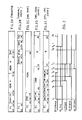
- Fig. 3A, 3B, 3C, 3D, 3E show the format of the several basic types of microinstructions, that is the meaning assumed by the several bits forming each microinstruction.
- microinstructions are of two types: OPERATIVE microinstructions (fig. 3A, 3B) and JUMP microinstructions (fig. 3C, 3D, 3E).
- OPERATIVE microinstructions may be TRANSFER microinstructions (fig. 3A TRANSFER) or LOGIC/ARITHMETIC operative microinstructions (fig. 3B LOGICAL/ARITM).
- a transfer microinstruction comprises several fields of bits having a precise meaning.
- a first field (bits 0-3), named FC or FUNCTION CODE, characterizes the micro- instruction and assigns to the subsequent fields a determined meaning.
- Decoding network 4 (fig. 1 B) decodes such function code and, according to it, distributes subsequent bit levels, turned into electrical levels, to determined outputs of theirs.
- the electrical levels at such outputs control the several registers and the several gates constituting the system in order to perform the function defined by the microinstruction bits.
- a second field (bits 04-07), named BLOCK SEL or block selector, defines which are the system elements involved in the transfer.
- the transfer microinstruction can control the information transfer from a register of a bank to a register of another bank, or from the output register of the working memory to an output register of channel interface, etc. (Such considerations are referred to the specific architecture described in the already mentioned US ⁇ A ⁇ 4.001.784).
- a third field (bits 08-13), named ADDR A, defines the specific address of one of the registers involved in the transfer, for instance one of the registers of a bank or one of the output registers.
- ADDR B A fourth field (bits 14-21), named ADDR B, defines the specific address of the other register involved in the transfer.
- a fifth field (bit 22), named DIR, defines the transfer direction, that is if the transfer has to occur from the location defined by ADDR A to the one defined by ADDR B or viceversa.
- bits 23-31 are used for control functions and as parity check bits.
- Fig. 3B shows the format of a LOGIC/ARITHMETIC operative microinstruction.
- bits 0-3) with meaning of function code FC there is a field (bits 0-3) with meaning of function code FC, a field (bits 18-20) with meaning of address of the register (SOURCE) containing the operand (the operator may be stored in a fixed register), a field (bits 21-23) which defines the logic/arithmetic operation to be executed (OP SEL), a field (bit 24-26) which defines the address of the register where the operation result is to be stored, and a field IR (bit 29) which defines whether the index register is to be updated with the conditions of carry/over- flow/etc. which have occurred owing to the operation.
- microinstructions do not contain, contrarily to the jump ones, any useful information defining the subsequent microinstruction address.
- the subsequent microinstruction will be therefore called for by the sequencer through the increment by one unit of the previous operative microinstruction address.
- Fig. 3C shows the format of an absolute jump microinstruction (ABS. JUMP).
- Such kind of microinstruction specifies the address of the following microinstruction itself.
- a first field (bits 0-5) constitutes the function code.
- a second field defines whether the progressive address of the jump microinstruction in progress, incremented by one unit, must be saved into stack 20 in order to be called for later on; if bit 06 is at logical level 1, the saving operation occurs.
- a third field (bit 07-22), named ADDR, constitutes the absolute address of the subsequent microinstruction.
- Fig. 3D shows the format of a relative conditioned jump micro- instruction (REL. COND. JUMP).
- Such kind of microinstruction having a generical address N, defines that the subsequent microinstruction must be the one having address N+1 if a condition specified by the same microinstruction is not verified, and must be the one having address N+K if the condition specified by the same microinstruction is verified.
- the displacement K is provided by the same microinstruction.
- a first field (bit 0-5) defines the function code.
- a second field (bit 06), named SAVE, defines whether the progressive address of the jump microinstruction in progress, incremented by one unit, must be saved into stack 20 in order to be recalled later on.
- a third field (bit 07), named C DR, defines whether the condition to be verified is contained in a DIRECT REGISTER.
- a fourth field defines which is the condition COND to be verified.
- a fifth field (bit 17-29) defines the displacement K.
- Such microinstruction is typical for the start of a subroutine or of an interrupting microprogram and for the return from a subroutine or from an interrupting microprogram.
- a first field defines a function code and a second field (bit 06), named SAVE, indicates if the progressive address of the jump microinstruction in progress, or, more generally, the address present in register ROSPA, incremented or not by one unit, must be saved into stack 20 in order to be recalled later on.
- a third field (bit 07), named RD DR, defines if the content of a DIRECT REGISTER must be read out and transferred into register IR7.
- a fourth field (bit 08), named WR DR, defines if the content of register IR7 must be saved by writing it in a DIRECT REGISTER.
- a fifth field (bit 09), named RET, defines if the microinstruction is a microinstruction of return from a subroutine or from an interrupting microprogram; in this last case a pop operation of stack 20 is commanded and the subsequent microinstruction address is read out from stack 20.
- a sixth field (bits 10-13), named DR ADDR, defines which DIRECT REGISTER of stack 9 is interested in the transfer (read or write).
- PC PRIORITY CHANGE
- a start address 0 is forced on channels 38 and 39 and is applied to inputs of incrementer 22.
- Such address is loaded into registers 17 (ROSPA) and 3 (ROSAR) by the rising edge of signal STCSSA, while address +1 is loaded into counter ⁇ CPCR21.
- a read operation of ROS memory 1 starts, at the end of which the microinstruction of address 0 is available on the output of such memory.
- the read out microinstruction is loaded into register ROR 2 by the rising edge of timing signal STRORA, so that the microinstruction is available on inputs of decoder 4 and a set of microcommands is produced on the outputs of decoder 4.
- microcommands allow the micro- instruction execution during the cycle.
- Microcommands So and S 1 at logical level 0 are two of the microcommands generated by decoder 4 and they are available from time to.
- Such microcommands select input set 31 of multiplexer 23, so that the new address "1", present in register ⁇ PCR21, is transferred on channels 38 and 39 and applied to inputs of incrementer 22.
- the new address N+ is transferred by the rising edge of STCSSA from ⁇ PCR21 to channels 38, 39 through multiplexer 23, AND gates 25, tristate circuits 24, and then loaded into registers ROSPA and ROSAR.
- field IR may define, if at logical level 1, that register IR7 must be loaded with the conditions verified during the execution of such microinstruction.
- Such conditions coming from a condition check network, not shown, are transferred through multiplexer 8 (enabled by a microcommand S 4 ) to inputs of register 7 and loaded into it by the rising edge of a signal STSNA ⁇ !R which is obtained as a logical AND of microcommand IR with timing signal STSNA.
- Register IR7 is therefore loaded at time t 3 and its outputs are connected, through AND gates 15 enabled by STSNA ⁇ IR, to channel 14 which supplies decoding network 4.
- microcommands So S 1 assume a logical condition which selects input set 29 of multiplexer 23 and microcommands S 2 S 3 assume a logical level which selects inputs OOOF of multiplexer 19.
- Field 07-22 defines a new address NA to be used to address the subsequent micro- instruction: such bit field is transferred through channels 41, 42 to an input set of multiplexer 19.
- the microinstruction decoding produces a group of microcommands S 2 , S 3 at logical level such as to select the input set of multiplexer 19 connected to channel 42, as well as a set of microcommands S 0 , S 1 which select input set 29 of multiplexer 23.
- new address NA is loaded into registers ROSPA 16 and ROSAR 3, while address N+1 contained in ,uPCR21 is loaded into register 20A of stack 20.
- address NA+1 present on outputs of network 22 is loaded into register ,uPCR21.
- the new microinstruction which will be recalled, will therefore be the one of address NA, while the sequential address N+1 is saved into stack 20 and will be recalled later on.
- an address N is loaded into registers ROSPA 17 and ROSAR 3 and an address N+1 is loaded into register ⁇ PCR21.
- Field 17-29 defines a jump displacement K to be used to address the subsequent micro- instruction if a determined condition is verified.
- Such bit field is transferred, through channel 41, to input set B of summing network 18 which receives on its input set A the address N coming from ROSPA through channel 40.
- microinstruction bit 07 defines whether the condition to be examined is contained in a register DR of bank 9, whose address is expressed by the field of bits 10-13.
- addressing microcommands of bank 9 and a read microcommand RDR are generated by network 4.
- Timing signal PH2 therefore controls the reading of the selected register.
- the selected register content defines the condition to be examined and is transferred through multiplexer 8, controlled by microcommand S 4 at suitable logical level, to the inputs of register IR7.
- Such network selects in the contained information the condition to be verified and, if this last one is verified, it generates a set of microcommands S 2 , S 3 at a logical level such as to select the input set of multiplexer 19 which is connected to the output set of summing network 19, and a set of microcommands S 0 , S, which select input set 29.
- microcommands FILE EN at logical level 0 and PUSH/POP at logical level 1 are also generated.
- address N+K is loaded into ROSPA 17 and ROSAR 3
- address N+1 contained in ,uPCR21 is transferred to register 20A of stack 20 and address N+K+ is loaded into ⁇ PCR21.
- Such completely asynchronous event is considered at a suitable time of a machine cycle; it is recognized only if there are not interruption requests of higher priority or interruption requests in progress having the same priority level and is presented to the central unit in order to develop an interruption execution microprogram.
- such network provides leads 99, 154, 150, with signals indicating an interruption having high, mean, low priority and leads 158, 159, 161, 162 with signals indicating an interrupting channel.
- the number of such leads is variable and it depends on the number of priority levels that the system is able to consider and on the number of interface channels.
- Fig. 1B is considered and assumption is made that an intermediate priority interruption occurs on lead 154 during the initial phase of a machine cycle and that, at the same time, a signal of interrupting channel is applied to lead 158.
- flip-flops 52 and 53 are reset.
- the interruption is therefore transferred through AND 48, is applied to vector generator 45 and, through OR 43, is applied to an input of AND gate 44.
- the interruption is transferred to lead 50 by the rising edge of STINTA and it enables tristate circuits 46, while NOT 51' applies a logical level 0 to input CN.
- the interruption signal is present on lead 50 for a suitable portion of the cycle, that is from time t 4 (signal STINTA rising to 1) up to time t 7 , when signal STINTA falls to logical level 0.
- the several commands So, S 1 , S 2' S 3 enable multiplexers 19 and 23 to transfer address N+1 to output set 28 of sequencing unit 16 and to inputs of incrementer 22.
- address N+1 is not loaded into registers ROSPA and ROSAR by the rising edge of STCSSA.
- Microinstruction MI is therefore addressed and it is executed during the subsequent cycle.
- micro- instruction is a jump microinstruction and not an operative microinstruction and it allows to save the machine states existing before the interruption.
- microinstruction has the format shown in fig. 3E.
- a first field (bits 0-5) constitutes the function code.
- a second field (bit 06), named SAVE, in this case at logical level 1, defines that the preexistent microprogram address must be saved.
- a third field (bit 07), named RDR, is not used in this case and is at logical level 0.
- a fourth field (bit 08), named WDR, is at logical level 1 and determines that the information contained in register IR7 must be saved into a DIRECT REGISTER.
- a fifth field (bit 09), named RET, is in this case at logical level 0 and is not used.
- a sixth field (bit 10-13), named DR ADDR, determines the DIRECT REGISTER address to be used for the writing operation specified by bit 08.
- a seventh field (bit 14), named PC, is in this case at logical level 0 and is not used.
- An eighth field (bit 17-29), named K, defines the jump displacement K to be used to establish the subsequent microinstruction address.
- the called microinstruction of address MI contains the following useful information:
- DR ADDR information allows to select a register of bank 9.
- timing signal STCSSA address N+1 present in ⁇ PCR21 is saved by loading it into stack register 20A and address MI+1 is loaded into ROSPA 17 and ROSAR 3.
- a new address MI+2 which can be used for the following sequential addressing of the microprogram, is loaded into ⁇ PCR21.
- MI+2 which can be used for the following sequential addressing of the microprogram
- register ⁇ PCR21 contains address N+1.
- interrupting microinstruction is a jump micro- instruction (with saving) which does not use, for the address increment, network 22 and register jM PCR21 as temporary store, but it uses a path different from the first one.
- Such different path has only a section in common with the first path and is provided with summing network 18 and with temporary storing register of the addresses (ROSPA).
- register ⁇ PCR21 can be used as temporary register of the jump address which can therefore be saved.
- the unconditioned relative jump micro- instruction having the format shown in fig. 3E, is also used as return microinstruction both from interrupting microprogram and from subroutine.
- the last microinstruction of the microprogram is of the type shown in fig. 4E.
- Field 09 is at logical level 1 and commands, when decoded, a pop operation of stack 20: the address of the following micro- instruction is read out from stack 20.
- the flip-flops indicating the several priority levels are flip-flops 52, 53, 54.
- Fig. 1B shows that an high priority interruption INT HP is transferred through AND gate 47 only if flip-flop 52 was reset.
- interruption INT HP addresses the interruption treatment microprogram by means of signals STINTA (which enables AND gate 44) and by signal STCSSA.
- flip-flop 52 is set by the falling edge of PH2, because its J input is at logical level 1.
- the set of flip-flop 52 locks AND gate 47 and, from now onwards, interruption INT HP may be removed from lead 99.
- the set of flip-flop 52 also locks gates 48 and 49 so that the interruptions having lower priority level cannot be recognized too.
- an intermediate priority interruption if it is recognized, sets flip-flop 53, which inhibits, till it is set, that other subsequent interruptions having intermediate or low priority be recognized.
- a low priority interruption INT BP if recognized, sets flip-flop 54, which inhibits, till set, that other subsequent low priority interruptions be recognized.
- PC priority level
- Field 14 when it is decoded, generates a microcommand EOS which is applied to K input of flip-flop 52 through lead 57, and to K input of flip-flops 53, 54 through AND gates 55 and 56 respectively.
- sequencer is able to generate microprogram addresses with possibility of inserting subroutines at the same priority level and saving microprogram addresses, as well as with possibility of interrupting microprograms to jump to interrupting microprograms, and saving addresses and, finally, of returning from such subroutines or interrupting microprograms.
- a first loop is formed by multiplexer 23, by AND gate set 25, by incrementer 22, by register ,uPCR21 and by the connection between output set of juPCR21 and input set 31 of multiplexer 23.
- a second loop is formed by multiplexer 23, by gate sets 25 and 24, by channel 39, by register 17, by channel 40, by summing network 18, by multiplexer 19 and by the connection between the output set of multiplexer 19 and input set 29 of multiplexer 23.
- the use of two multiplexers 19 and 23 connected in cascade is arbitrary and is due to the advantage of using a component (sequencing unit 16) available on the market.
- multiplexers 19 and 23 may be included in one multiplexer 23A, as shown in fig. 4.
- the two address generation loops, essential for the sequencer working, are evidenced by a double line.
- Fig. 5 shows a second modified embodiment of the sequencer of fig. 1A; such modified embodiment uses two multiplexers and differs from fig. 1A only because multiplexer 19 is downstream of multiplexer 23. Also in this figure the elements corresponding to those of fig. 1 A are identified by the same reference numbers and the two address generation loops are evidenced by a double line.
Description
- The present invention relates to microprogram sequencers for microprogrammed control units of data processing systems as set out in the first portion of
Claim 1. A microprogram sequencer is a set of circuits which determines the orderly read out of the microinstructions stored in a control memory, that is the orderly read out of the microprograms in a control unit of a data processing system capable of performing operations of internal computation, of information transfer with a working memory and, at the same time, capable of managing the operation of peripheral devices. - It is known that data processing systems generally comprise a central unit, a main work memory and a plurality of peripheral units connected to the central unit by means of a plurality of input/output channels for the exchange of information.
- The data processing system job consists of processing some data according to well defined program instructions.
- From the logical point of view the central unit comprises a control unit and an operative unit.
- The program instructions are interpreted and executed by means of microprograms, that is microinstruction sequences that the control unit reads out from a control memory, one micro- instruction at a time. Through suitable decoding of the microinstructions a set of elementary commands, or microcommands, is generated which cause the working of the several logic/electric networks of the central unit in the manner required by the several program instructions.
- The operative processes performed by the system may be internal, that is executed within the central unit with possible data exchange with the working memory, or external, that is requiring the intervention of peripheral units.
- In the second case they require an information transfer between some peripheral units and the central processing unit through input/output channels which connect the peripheral units to the central processing unit.
- The operative processes which develop within the peripheral units are synchronized neither among them nor with the ones which develop within the central unit.
- Therefore, the whole system monitoring is not carried out by one program, univocally determined as to the timing, but it is rather performed with "interruptions" which require the execution of predetermined services.
- The "interruptions" can be caused by interrupt requests coming from peripheral units.
- Owing to an interrupt request, the central unit must interrupt the execution of an internal process in progress in order to execute the service required by the peripheral unit.
- As already mentioned, the "interruptions" are asynchronous events which may occur at any time and phase of the internal processes and which, generally, require the immediate interruption of the process in progress and the immediate execution of the required service; this is particularly true in case the interrupt requests come from fast peripheral units, such as disk units.
- In microprogrammed central units this involves the interruption of microprograms in progress, through which the program instructions of the internal process are executed, and the start of microprograms executing the services required by the interruption.
- However, when an interruption occurs, information about the status of the internal interrupted process must be saved in order to resume such process once the required service has been executed.
- This problem has been solved, in the prior art, by a multiplication of resources, particularly of registers, devoted to the storing of the microprogram address and determined states of the several overlapping processes.
- For instance, in US-A-4.001.784 the control unit of a data processing system comprises three microprogram address registers. A first register is used to store the addresses of the microprogram which performs the program instructions of the internal processes; a second register is used to store the addresses of the microprogram executing the services required by interruptions having a certain priority level; a third register is used to store the addresses of the microprogram executing services required by interruptions having another priority level.
- Such structure allows to save microprogram addresses which, otherwise, would be lost owing to the interruptions, but it is not effective for the "saving" of addresses which should be saved within the same program. Such concept may be explained by referring to microprogram structures. It is known that the several program instructions of an operative process are executed by microprograms consisting of a set of microinstructions stored in a control memory.
- The microinstructions are preferably arranged in sequence to form a microprogram.
- In other words, a microinstruction stored in a memory address n is followed by a micro- instruction stored in address n+1, and so on. In such a way the memory addressing operation, may be carried out by a network which increments the preceding address by one unit.
- The network is particularly simple and unexpensive.
- However such criterium cannot be always adopted.
- First of all, during the execution of a microprogram, it is often necessary to choose between two possible paths, according to particular conditions which occur and, for one at least of such paths, the sequential addressing is no longer possible.
- Further, the several microprograms, each one allowing for the interpretation of a well determined program instruction, may contain portions formed by identical microinstruction sequences.
- To avoid a memory waste it is suitable to store such microprogram portions in the control memory once only as to avoid duplications. Such microinstruction portions or sequences, identical for several microprograms, are named "subroutines" and it is clear that, for all the microprograms which use them, possibly with the exception of one, the access to such subroutines cannot follow the general criterium of sequential addressing.
- During the microprogram execution some jump microinstructions, for sake of precision unconditioned jump microinstructions, are therefore provided: the execution of such jump microinstructions causes the interruption of the sequential addressing operation and the jump to a microinstruction whose address is determined by the information contained in the jump microinstruction.
- If all the subroutines were final portions of the microprograms, their execution would complete the microprogram which has called for one of them and there will be no further problems.
- On the contrary a subroutine may also form an intermediate portion of a microprogram. It is therefore necessary, at the end of the subroutine, to return to the specific microprogram by which the subroutine has been called.
- Evidently, the subroutine is not able by itself to specify to which of the several microprograms it has to go back and which must be the subsequent return address in the microprogram basic sequence.
- Therefore, the return address necessary to go back to the main microprogram after the execution of a subroutine, must be previously saved before starting the subroutine in a suitable register.
- Generally the address to be saved is the jump microinstruction address, which calls for the subroutine, incremented by one.
- The last microinstruction of the subroutine must contain a command information which controls the return, that is the addressing of the subsequent microinstruction by using the saved address.
- However, it cannot contain information concerning the specific register where the address has been saved, but the read out from the register of address to be used must be automatically obtained.
- Generally a subroutine may also contain, in its turn, microprogram portions common to other subroutines or microprograms, which will be considered subroutines of second level or of subsequent level. It will be therefore necessary to provide a number of address saving registers equal to the subroutine levels which are foreseen and an automatic mechanism of return, that is of selection of one of these registers.
- A particularly effective solution of such problem is described in US-A-3,909,797.
- According to the solution suggested by such patent the registers devoted to save the several return addresses form a stack where the output order of the information stored therein is opposite to the input order, that is information is handled on a last in, first out basis (LIFO).
- In other words the last recorded information is always the first one to be read out.
- This allows the "nesting" of subroutines of different level, the one inside the other, and the orderly return to the several subroutines up to the internal computation microprogram.
- However such solution does not consider the problems rising from a microprogrammed system where a microprogram interruption may be caused by external events; in fact the above solution does not satisfy the requirements of a control unit which jointly uses microprograms comprising common subroutines and interruption mechanisms.
- A partial solution to such problem is offered by microprogram sequencers of the type described in the mentioned US-A-3,909,797, which are now present on the market in form of integrated circuits, as for instance the circuits with code 2911 and 2910 manufactured by Advanced Micro Devices Inc.
- A clear description of such circuits may be found in the article by Claude Brie: "Panorama des processeurs en tranches. I- les sequenceurs" (Publication: Le Nouvel Auto- matisme, Vol. 24, No. 1/2, Janvier/Fevrier 1979,
pages 31 to 39. - The mentioned integrated microprogram sequencers comprise the features set out in the first portion of
Claim 1, e.g. a multiplexer which transmits to its output set one of several addresses present on its input sets and coming form: - -the outside (directly or through an internal address/holding register),
- -an internal microprogram counter register latching the address of the microinstruction in progress incremented by one,
- - an internal register stack of LIFO type (last in first out).
- Such integrated sequencers, suitably controlled, may supply the addressing inputs of a control memory with a sequential address, a return address from subroutine and a jump address to subroutine.
- In case of jump to subroutine, the jump address is generally provided in absolute way by a suitable field of the jump microinstruction in progress.
- Such jump address is therefore applied to the input set of the sequencer multiplexer devoted to receive information from the outside. When interruption mechanisms are provided for in the system, the same input set of multiplexer may receive through control gates an external microprogram address provided by an interrupting unit of the system. In such way, if an interruption is enabled during the execution of a microinstruction of address N, in the following machine cycle the microinstruction addressed by the interruption address is executed and, at the same time, the saving of address N+1 into stack is performed. It is obvious that the interruption microprogram ends with a micro- instruction allowing the return to the interrupted microprogram.
- However if an interruption occurs during execution of a microinstruction which call for non sequential addressing of the next one, such as for instance a jump microinstruction, the described arrangement and particularly the multiplexer constitutes a real bottleneck for the simultaneous transfer of two different addresses, one to the stack for saving purpose, the other to the control memory for addressing of the first microinstruction of the interrupting microprogram.
- Interference occurs.
- Moreover it may even be required to save two addresses, such as, in case of jump to subroutine microinstruction with address saving, the address N+1 of the next sequential micro- instruction and the address K of the subroutine first microinstruction.
- Thus the solution offered by the prior art is limited by this constraint. This constraint might be overcome by taking interruptions into consideration only on the occurrence of selected microinstructions, with a firmware approach which involves a relatively slow interrupt response time, or through the use of expensive additional circuits, such as interruption mask- unmask logic responsive to the nature of the microinstruction in progress and deferring of the interrupt consideration whenever required.
- These disadvantages are overcome in a simple and unexpensive way by the microprogrammed control unit sequencer of the present invention as set out in
Claim 1 which, in addition to the integrated sequencer such as the mentioned AMD 2911, providing a looped communication path for the sequential increment of the addresses and stack for address saving, comprises a second looped communication path including a present address register (ROSPA) and a summing unit for non sequential address generation. - The second communication path has in common with the first communication path a first address node, and is further provided with a second address node immediately upstream said present address register, through which node interrupt addresses are received.
- By this arrangement the following advantages are achieved:
- When an interrupt address is received at the second address node during execution of whatever microinstruction, the present address register may be loaded with such address and the memory addressing can be performed without interfering in the first and second looped communication path with the flow, updating and saving of the address already contained in the present address register and in the microprogram counter register of the sequencer.
- This is particularly true for jump micro- instruction with address saving. Therefore interruptions may arise, without delay, during execution of whatever microinstruction.
- The sole constraint intrinsic in such architecture is that the first microinstruction of the interrupt microprogram must be a jump micro- instruction with saving of address, to provide, during its execution, the saving in the stack of the address contained in the microprogram counter register, and the generation of the next address through the second looped communication path.
- By this, the further advantage is obtained to secure an homogeneous format to the program microinstructions: the saving function, specified by a predetermined microinstruction bit, is only present in the jump microinstructions, where it may be necessary.
- Such function is not present, in any case, in the sequential microinstructions where it would be unuseful and where the utilization of a bit with such a specific use is inconsistent with the need to assign a different meaning to the several microinstruction bits. Ways of carrying out the invention will appear more clearly from the following description of preferred embodiments of the invention and from the enclosed drawings where:
- Fig. 1 shows how fig. 1A and 1B are to be juxtaposed for their reading.
- Fig. 1 A and 1 B jointly show a microprogrammed control unit comprising a sequencer according to the present embodiment.
- Fig. 2 shows the timing diagrams of some timing signals used in the unit of fig. 1 A and 1 B.
- Figures 3 (3A to 3E) show the format of the microinstructions used in the control unit of fig. 1A and 1B.
- Fig. 4 shows a slightly modified form of the sequencer of fig. 1A.
- Fig. 5 shows a second modified form of the sequencer of fig. 1A.
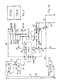
- Fig. 1 A and 1 B jointly show a microprogrammed control unit comprising a sequencer according to the present invention.
- The microprogrammed control unit of fig. 1A and 1 B may be associated to central processing units having a different architecture and which are not described herein because they are beyond the scope of the present invention.
- Particularly it may be used in the data processing system described in US-A-4.001.784 to which reference is made in order to have a complete understanding of the whole central processing unit.
- In such a central processing unit, fig. 1A and 1B of the present invention integrally replace the circuits shown in fig. 8a and 8b of the mentioned patent.
- The control unit substantially comprises (fig. 1 B):
- - a control memory or
ROS 1 where the microprograms are stored; - - an output register 2 (ROR) for ROS memory, receiving and storing at each machine cycle a microinstruction read out from
ROS memory 1; - - an addressing
register ROSAR 3 having its outputs connected to the address inputs ofROS memory 1 and receiving and storing at each machine cycle a ROS address; - - a microinstruction decoder 4 which receives on its inputs the microinstruction contained in
register ROR 2 and decodes it providing on its outputs elementary commands or microcommands. Such decoder may be of the type described in the US-A-3.812.464 which decodes the microinstructions according to a field of the sames, the field having variable length and being named function code. Fig. 1 B shows, as an output from decoder 4, only the microcommands necessary for the understanding of the embodiment and precisely So, S1, S2, S3, S4, FILE EN, PUSH/POP, RDR, WDR, DR ADDR, EOS, IR; - ―a
timing unit 5 which cyclically generates timing signals for each machine cycle. Such timing signals are forwarded to the several elements forming the central unit for timing them. Fig. 1 B shows as an output fromunit 5 the signals necessary for understanding the invention, and precisely: STRORA, PH2, STCSSA, STINTA, STSNA; - ―a
timing network 6 which receives on its inputs microcommands decoded by decoder 4 and timing signals produced bytimer 5.Network 6 performs logical AND operations among timing signals and microcommands, and supplies on its outputs suitable timed microcommands during each machine cycle. - In fig. 1B only signal STSNA · (IR+S4) is shown as an output from
network 6, which signal is necessary for a full understanding of the embodiment; - -the control unit further comprises an
index register IR 7 intended to receive and to store particular machine statuses or conditions, as for instance the occurrence of an input (CI) or an output (COT) carry due to arithmetical or shift operations, or the occurrence of conditions, detected by comparison and indicated by a positive comparison signal NZ2. - These statuses received from other central unit elements (described for instance in the mentioned US-A-4.001.784) are sent to inputs of register IR7 through a two
path multiplexer circuit 8. A bank of registers DR9 is further provided, which may be addressed by microcommands. - The content of register IR7 may be saved in such bank and from there the previously saved statuses may be read out and reloaded in the index register IR7. To this purpose, the outputs of index register IR7 are connected through a
channel 10 toinputs 11 of register bank 9, and theoutputs 12 of register bank 9 are connected, throughchannel 13, to a set of inputs ofmultiplexer 8 which may selectively transfer to index register 7 the statuses read out from bank 9 or the statuses which occur during a machine cycle. - The outputs of
index register 7 are further connected, through achannel 14 and agroup 15 of enabling AND gates, to decoder 4, and provide it with information which adds to the one obtained from the read out microinstruction. - The control unit sequencer, that is the circuit set devoted to the
control memory 1 addressing, comprises (Fig. 1A): - - a
sequencing unit 16 carried out by the already mentioned integrated circuit Am 2911; - - an auxiliary register 17 (ROSPA) intended to contain the address of the microinstruction in course of execution;
- - a summing
network 18; - ―a
multiplexer circuit 19. - The
sequencing unit 16 substantially comprises: - ― a
stack 20; - - a microprogram counter register µPCR21;
- - a + counter or
incrementer 22; - - a
multiplexer circuit 23; - - a
set 24 of tristate output control circuits; - - a
set 25 of AND gates; - - an
inverter 26 connected to the control input of thetristate set 24. - The
sequencing unit 16, in the whole, has a set 27 of address inputs (by connecting in parallel a suitable number of integrated circuits AM 2911, any desired parallelism can be obtained), aset 28 of address outputs and a certain number of control inputs. - Two pins So and S, are used to control
multiplexer 23. -
Multiplexer 23 is provided with three sets of inputs and transfers the signals present on one of the three input sets to its output depending on the logical combination of the signals present on So, S1 inputs. - An input set 29 of
multiplexer 23 is connected to input set 27. - A second input set 30 is connected to outputs of
register stack 20 and a third input set 31 is connected to the outputs of microprogram counter register µPCR21. - Outputs of pPCR21 are further connected to the inputs of
register stack 20. - Outputs of
multiplexer 23 are connected to inputs of AND gate set 25, the AND gates being enabled by a signal ZERO atlogical level 1 applied to acontrol input 32. - The outputs of AND set 25 are connected to the inputs of the tristate output set 24 and to the inputs of
incrementer 22. - The tristate output set 24 is enabled to the information transfer by a command signal applied to an input pin OE connected to the enabling inputs of
tristates 24 throughinverter 26. -
Incrementing counter 22 is controlled by a signal CN applied to input 33. - When CN is at
logical level 1counter 22 increments by one unit the binary information applied to its inputs and transfers it on its outputs; when CN=0 the binary information applied to inputs ofcounter 22 is transferred unchanged. - The loading of register pPCR21 and of
stack 20 is controlled by a timing signal CK applied to aninput 34. - When CK signal rises from 0 to 1, register µPCP21 is loaded and, in case, stack 20 is enabled too.
-
Stack 20 comprises 4 cascade connectedregisters control inputs 35 and 36 respectively. - When FILE EN=1 no operation is performed by
stack 20. - When FILE EN=0
stack 20 operates according to signal PUSH/POP. - In case PUSH/POP=1 the information present on the output of ,uPCR21 is stored in register 20A with the rising edge of signal CK (it is therefore available on
inputs 30 ofmultiplexer 23 through channel 37). At the same time the information previously stored inregisters 20A, 20B, 20C is transferred or pushed intoregisters - In case PUSH/POP=0, the information stored in
register 20D, 20C, 208, is transferred or popped intoregister 20C, 20B, 20A respectively, with the rising edge of signal CK. - The information present, at this point, in register 20A is directly available on
inputs 30 ofmultiplexer 23 throughchannel 37. -
Outputs 28 ofsequencing unit 16 are connected, throughchannel 38, to the inputs of the memory addressing register 3 (ROSAR). - Such outputs are further connected, through channel 39, to the inputs of
present address register 17 whose outputs are connected, throughpath 40, to a first input set A of summingnetwork 18, which receives throughpath 41, on a second input set B a certain number of microinstruction bits read out fromROS memory 1. - The outputs of summing
network 18 are connected to a first input set ofmultiplexer 19, which receives on a second input set, throughpaths ROS memory 1. - A third input set of
multiplexer 19 receives a fixed binary addressing code: for instance OOOF. - The outputs of
multiplexer 19 are connected toinputs 27 ofsequencing unit 16. - The selection of the input set is determined by the logical level of the two signals on control inputs S2, S3.
- The sequencer is completed by some circuits for connection to a logical priority network intended to detect the interruptions coming from several channels connecting peripheral units.
- The logical priority network may be of the type described and shown in fig. 7 of the mentioned US-A-4.001.784.
- Such priority network emits on one of three output leads 99, 150, 154 an interrupt signal having high, low, intermediate priority respectively. On one of four
leads logical level 1 which indicates which is the channel sending the interruption. - For instance a
channel 1 is associated to lead 158, achannel 2 to lead 159 and so on. - One or more peripheral units will be connected to each channel through a peripheral adapter or peripheral control unit.
- Turning to fig. 1B, leads 99, 150, 154 are connected to the inputs of an
OR gate 43, each one through an ANDgate - Or 43 output is connected to an input of a two input AND
gate 44; ANDgate 44 is controlled by a cyclical timing signal STINTA (INTERRUPTION STROBE) applied to its second input. - The output of AND
gate 44 is connected, throughlead 50, to input OE ofsequencing unit 16. - When OE is at
logical level 1 theoutputs 28 of thesequencing unit 16 are locked (in high impedance output status). - Output of AND
gate 44 is further connected to control input CN ofsequencing unit 16 through aNOT 51 and to the control input of atristate set 46. - Tristate set 46 receives as an input an interruption vector (that is the first micro- instruction address of the microprogram called for by the interruption) and transfers such vector on
channel 38 and on channel 39 when it is enabled by ANDgate 44 with output atlogical level 1. - The interruption vector is generated by a logical network 45 (VECTOR GENERATOR) which suitably codes the input signals, constituted by the interruption signals at different priority level (received on
leads leads - The circuital structure of
logical network 45 is beyond the scope of the invention; this network is substantially a coding network which generates an address binary output code onchannel 51 depending on the binary code received on its inputs (7 bits two of which at logical level 1). - In alternative, in order to have a higher flexibility, the interruption vector generator can be constituted by a coding network which generates an addressing binary output code which addresses, in its turn, an auxiliary memory where the interruption addresses are stored.
- The vector generator outputs are connected to the inputs of tristate set 46 through
channel 51. - AND
gates flops gates 55, 56 (fig. 1 B) provide suitably timing of interrupt signals and interrupt masking if a higher priority interruption was already in progress. - Output of AND
gate 47 is connected to J input of flip-flop 52; output of ANDgate 48 to J input of flip-flop 53 and output of ANDgate 49 to J input of flip-flop 54. - The inverted output of flip-
flop 53 is connected to an input of ANDgates - The inverted output of flip-
flop 54 is connected to an input of ANDgate 49. - The inverted output of flip-
flop 52 is further connected to an input of ANDgates flop 53 is connected to an input of ANDgate 56. - A microcommand EOS (end of service) is applied to K input of flip-
flop 52 throughlead 57 and to an input of ANDgates flops - Flip-
flops - The set of such flip-flops determines the interruption level which is in progress.
- The timed operation of such network will be explained later on.
- Before explaining the operation of the sequencer object of the present invention, a brief description is made about the system timing and the organization of the microinstructions controlling it with particular reference to the sequencer working.
- Fig. 2 shows, in timing diagram, the signals produced by timing
unit 5 which are useful for understanding the sequencer working. - A machine cycle consists of a time interval, from time to to time t'o which is the beginning of the subsequent cycle.
- A machine cycle start is determined by a timing signal STRORA (diagram a) which rises to
logical level 1 at time to and remains atlogical level 1 up to time t5. - The rising edge of STRORA is used as strobe signal for register ROR2. At a time t2 a second signal PH2 (diagram b) rises to
logical level 1 and remains at such level up to time tio, - The rising edge of PH2 is used as strobe signal for register stack 9, whilst the falling edge of PH2 is used as clock signal for flip-
flops - At a time t3 a third signal STSNA (diagram c) rises to
logical level 1 and remains at such level up to time t7. - The rising edge of STSNA is used as timing signal applied to
network 6. - When one of microcommands IR or S4 is present, it produces a timed microcommand STSNA (IR+S4) used as strobe signal for
register 7. At an instant t4 a fourth signal STINTA (diagram d) rises tological level 1 and remains at such level up to a time t7. Such signal is used to enable ANDgate 44. - At a time t6 a fifth signal STCSSA (diagram e) rises to
logical level 1 and remains at such level up to time t9. - The rising edge of STCSSA is used as strobe signal for
register 3,memory 1, register 17 andsequencing unit 16. - Times to, t2 ... t", orderly follow in the time.
- The organization of the microinstructions is now considered, such microinstructions controlling during each machine cycle the operation of the sequencer, the control unit and the whole data processing central system.
- Fig. 3A, 3B, 3C, 3D, 3E show the format of the several basic types of microinstructions, that is the meaning assumed by the several bits forming each microinstruction.
- Essentially the microinstructions are of two types: OPERATIVE microinstructions (fig. 3A, 3B) and JUMP microinstructions (fig. 3C, 3D, 3E). The OPERATIVE microinstructions may be TRANSFER microinstructions (fig. 3A TRANSFER) or LOGIC/ARITHMETIC operative microinstructions (fig. 3B LOGICAL/ARITM).
- A transfer microinstruction comprises several fields of bits having a precise meaning.
- A first field (bits 0-3), named FC or FUNCTION CODE, characterizes the micro- instruction and assigns to the subsequent fields a determined meaning.
- Decoding network 4 (fig. 1 B) decodes such function code and, according to it, distributes subsequent bit levels, turned into electrical levels, to determined outputs of theirs.
- The electrical levels at such outputs control the several registers and the several gates constituting the system in order to perform the function defined by the microinstruction bits.
- A second field (bits 04-07), named BLOCK SEL or block selector, defines which are the system elements involved in the transfer.
- For instance the transfer microinstruction can control the information transfer from a register of a bank to a register of another bank, or from the output register of the working memory to an output register of channel interface, etc. (Such considerations are referred to the specific architecture described in the already mentioned US―A―4.001.784).
- A third field (bits 08-13), named ADDR A, defines the specific address of one of the registers involved in the transfer, for instance one of the registers of a bank or one of the output registers.
- A fourth field (bits 14-21), named ADDR B, defines the specific address of the other register involved in the transfer.
- A fifth field (bit 22), named DIR, defines the transfer direction, that is if the transfer has to occur from the location defined by ADDR A to the one defined by ADDR B or viceversa.
- Other fields (bit 23-31 ) are used for control functions and as parity check bits.
- Fig. 3B shows the format of a LOGIC/ARITHMETIC operative microinstruction.
- Also in this case there is a field (bits 0-3) with meaning of function code FC, a field (bits 18-20) with meaning of address of the register (SOURCE) containing the operand (the operator may be stored in a fixed register), a field (bits 21-23) which defines the logic/arithmetic operation to be executed (OP SEL), a field (bit 24-26) which defines the address of the register where the operation result is to be stored, and a field IR (bit 29) which defines whether the index register is to be updated with the conditions of carry/over- flow/etc. which have occurred owing to the operation.
- Other fields, not specifically shown, may assume suitable meanings. The operative microinstructions do not contain, contrarily to the jump ones, any useful information defining the subsequent microinstruction address.
- The subsequent microinstruction will be therefore called for by the sequencer through the increment by one unit of the previous operative microinstruction address.
- Fig. 3C shows the format of an absolute jump microinstruction (ABS. JUMP).
- Such kind of microinstruction specifies the address of the following microinstruction itself.
- A first field (bits 0-5) constitutes the function code.
- A second field (bit 06), named SAVE, defines whether the progressive address of the jump microinstruction in progress, incremented by one unit, must be saved into
stack 20 in order to be called for later on; ifbit 06 is atlogical level 1, the saving operation occurs. - A third field (bit 07-22), named ADDR, constitutes the absolute address of the subsequent microinstruction.
- Other fields, not specifically shown, may assume suitable meanings. Fig. 3D shows the format of a relative conditioned jump micro- instruction (REL. COND. JUMP).
- Such kind of microinstruction, having a generical address N, defines that the subsequent microinstruction must be the one having address N+1 if a condition specified by the same microinstruction is not verified, and must be the one having address N+K if the condition specified by the same microinstruction is verified.
- The displacement K is provided by the same microinstruction.
- Also in this case, a first field (bit 0-5) defines the function code.
- A second field (bit 06), named SAVE, defines whether the progressive address of the jump microinstruction in progress, incremented by one unit, must be saved into
stack 20 in order to be recalled later on. - A third field (bit 07), named C DR, defines whether the condition to be verified is contained in a DIRECT REGISTER.
- A fourth field (bit 08-16) defines which is the condition COND to be verified.
- A fifth field (bit 17-29) defines the displacement K.
- At last fig. 3E shows the format of a relative unconditioned jump microinstruction (REL. UNC. JUMP), with possible operations of saving and of return from subroutine and with possible priority change.
- Such microinstruction is typical for the start of a subroutine or of an interrupting microprogram and for the return from a subroutine or from an interrupting microprogram.
- Also in this case a first field (bit 0-05) defines a function code and a second field (bit 06), named SAVE, indicates if the progressive address of the jump microinstruction in progress, or, more generally, the address present in register ROSPA, incremented or not by one unit, must be saved into
stack 20 in order to be recalled later on. - A third field (bit 07), named RD DR, defines if the content of a DIRECT REGISTER must be read out and transferred into register IR7.
- A fourth field (bit 08), named WR DR, defines if the content of register IR7 must be saved by writing it in a DIRECT REGISTER.
- A fifth field (bit 09), named RET, defines if the microinstruction is a microinstruction of return from a subroutine or from an interrupting microprogram; in this last case a pop operation of
stack 20 is commanded and the subsequent microinstruction address is read out fromstack 20. - A sixth field (bits 10-13), named DR ADDR, defines which DIRECT REGISTER of stack 9 is interested in the transfer (read or write).
- A seventh field (bit 14), named PC (PRIORITY CHANGE), defines if a priority change must occur, for instance because a microprogram of interruption treatment ends.
- An eighth field (bits 17-29) gives the jump displacement K.
- Once described the format of the microinstructions used to control the central system and the sequencer object of the invention, as well as the essential timings of a machine cycle, the sequencer working may be examined in the different possible cases.
- To initialize the system it is enough to force by a start push button (not shown), which activates at the same time a machine cycle, a logical level 0 on
input 32 which locks ANDgates 25. - As assumption is made that no external interruption be present, a start address 0 is forced on
channels 38 and 39 and is applied to inputs ofincrementer 22. Such address is loaded into registers 17 (ROSPA) and 3 (ROSAR) by the rising edge of signal STCSSA, while address +1 is loaded into counter µCPCR21. - A read operation of
ROS memory 1 starts, at the end of which the microinstruction of address 0 is available on the output of such memory. At the subsequent cycle start (time to) the read out microinstruction is loaded intoregister ROR 2 by the rising edge of timing signal STRORA, so that the microinstruction is available on inputs of decoder 4 and a set of microcommands is produced on the outputs of decoder 4. - Such microcommands allow the micro- instruction execution during the cycle.
- Supposing that the read out micro- instruction is an operative microinstruction, it causes an address sequential updating.
- Microcommands So and S1 at logical level 0 are two of the microcommands generated by decoder 4 and they are available from time to.
- Such microcommands select input set 31 of
multiplexer 23, so that the new address "1", present in register µPCR21, is transferred onchannels 38 and 39 and applied to inputs ofincrementer 22. - At instant t6 the new address "1" is loaded into
registers - Generally, if at instant to of any cycle an operative microinstruction of address N is loaded into
register ROR 2, this means that during the previous cycle address N was loaded intoregisters ROSPA 17 andROSAR 3 and that address N+ was loaded into register µPCR21, all these loadings occurring at a time t6 by the rising edge of timing signal STCSSA. - During the cycle within which the micro- instruction of address N is executed, the new address N+ is transferred by the rising edge of STCSSA from µPCR21 to
channels 38, 39 throughmultiplexer 23, ANDgates 25,tristate circuits 24, and then loaded into registers ROSPA and ROSAR. - At the same time the content of µPCR21 is incremented to N+2.
- It is to be noted that, if the operative micro- instruction in progress is of the logic/arithmetic kind, field IR (bit 29) may define, if at
logical level 1, that register IR7 must be loaded with the conditions verified during the execution of such microinstruction. - Such conditions, coming from a condition check network, not shown, are transferred through multiplexer 8 (enabled by a microcommand S4) to inputs of
register 7 and loaded into it by the rising edge of a signal STSNA · !R which is obtained as a logical AND of microcommand IR with timing signal STSNA. - Register IR7 is therefore loaded at time t3 and its outputs are connected, through AND
gates 15 enabled by STSNA · IR, to channel 14 which supplies decoding network 4. - Some microcommands generated by such network are therefore modified. Particularly, if among the conditions received by register IR7 an ERROR condition is present, microcommands So S1 assume a logical condition which selects input set 29 of
multiplexer 23 and microcommands S2 S3 assume a logical level which selects inputs OOOF ofmultiplexer 19. - So, starting from time t3, when STSNA signal rises (or better with a certain delay due to the signal propagation time, but however before time t6) an address OOOF is forced, through
multiplexer 19,inputs multiplexer 23,gates 25,tristates 24, onchannels 38 and 39. A start address OOOF of an error treatment routine is therefore loaded into registers 17 (ROSPA) and 3 (ROSAR) by timing signal STCSSA. At the same time the address OOOF+ is loaded into register µPCR21, whilst the previous address contained into µPCR21 is lost. In fact, when an error occurs, it is unuseful to save information in progress (microprogram addresses included) in order to resume operations which have not been correctly executed. - Assumption is made that, during a general machine cycle n-1, an absolute jump micro- instruction of address N is addressed.
- At time t6 of cycle n-1
registers ROSPA 17 andROSAR 3 are loaded with address N and register µPCR21 is loaded with address N+1. - At time to of cycle n, the microinstruction of address N is available in register ROR2 and is decoded.
- Field 07-22 defines a new address NA to be used to address the subsequent micro- instruction: such bit field is transferred through
channels multiplexer 19. - The microinstruction decoding produces a group of microcommands S2, S3 at logical level such as to select the input set of
multiplexer 19 connected to channel 42, as well as a set of microcommands S0, S1 which select input set 29 ofmultiplexer 23. - Therefore new address NA is transferred on
channels 38, 39 and to inputs ofincrementer 22. - Besides, if bit 06 (SAVE field) is at
logical level 1, two microcommands FILE EN at logical level 0 and PUSH/POP atlogical level 1 are generated; such microcommands are applied toinputs 35, 36 of thesequencing unit 16 respectively. - At time t6 of cycle n, new address NA is loaded into
registers ROSPA 16 andROSAR 3, while address N+1 contained in ,uPCR21 is loaded into register 20A ofstack 20. - At the same time address NA+1, present on outputs of
network 22, is loaded into register ,uPCR21. The new microinstruction, which will be recalled, will therefore be the one of address NA, while the sequential address N+1 is saved intostack 20 and will be recalled later on. - If the microinstruction of address N was a jump microinstruction without address saving (that is
bit 06 SAVE was at logical level 0), the saving operation would not have occurred. - Assumption is made that, during a general machine cycle n-1, a relative conditioned jump microinstruction of address N is addressed.
- At time t6 of cycle n-1, an address N is loaded into
registers ROSPA 17 andROSAR 3 and an address N+1 is loaded into register µPCR21. - At time to of cycle n, the microinstruction of address N is available into register ROR2 and is decoded.
- Field 17-29 defines a jump displacement K to be used to address the subsequent micro- instruction if a determined condition is verified. Such bit field is transferred, through
channel 41, to input set B of summingnetwork 18 which receives on its input set A the address N coming from ROSPA throughchannel 40. - The microinstruction decoding produces a group of microcommands:
microinstruction bit 07 defines whether the condition to be examined is contained in a register DR of bank 9, whose address is expressed by the field of bits 10-13. - In the affirmative case, addressing microcommands of bank 9 and a read microcommand RDR are generated by network 4.
- Timing signal PH2 therefore controls the reading of the selected register.
- At time t2, the content of the selected register is available on output set 12.
- The selected register content defines the condition to be examined and is transferred through
multiplexer 8, controlled by microcommand S4 at suitable logical level, to the inputs of register IR7. - At time t3, by the rising edge of STSNA, the content read out from the selected register is loaded into register IR7 and transferred, then, through AND
gates 15 andchannel 14, to decoding network 4. - Such network selects in the contained information the condition to be verified and, if this last one is verified, it generates a set of microcommands S2, S3 at a logical level such as to select the input set of
multiplexer 19 which is connected to the output set of summingnetwork 19, and a set of microcommands S0, S, which select input set 29. - Besides, if
bit 06 is at logical level 1 (that is the command of saving into stack is present), microcommands FILE EN at logical level 0 and PUSH/POP atlogical level 1 are also generated. - So, as time t6, address N+K is loaded into
ROSPA 17 andROSAR 3, while address N+1 contained in ,uPCR21 is transferred to register 20A ofstack 20 and address N+K+ is loaded into µPCR21. - If the condition had not been verified, no saving would have occurred and the address loaded into
ROSPA 17 andROSAR 3 would be N+1, while the address contained in µPCR21 would be N+2. - Assumption is made that an interruption request is presented by a peripheral unit of the system.
- Such completely asynchronous event is considered at a suitable time of a machine cycle; it is recognized only if there are not interruption requests of higher priority or interruption requests in progress having the same priority level and is presented to the central unit in order to develop an interruption execution microprogram.
- These operations are performed by an interface priority network, not shown because it is beyond the scope of the invention.
- An embodiment of such network is described in the already mentioned US-A-4.001.784.
- For the invention purposes it suffices to point out that such network provides leads 99, 154, 150, with signals indicating an interruption having high, mean, low priority and leads 158, 159, 161, 162 with signals indicating an interrupting channel.
- The number of such leads is variable and it depends on the number of priority levels that the system is able to consider and on the number of interface channels.
- Fig. 1B is considered and assumption is made that an intermediate priority interruption occurs on
lead 154 during the initial phase of a machine cycle and that, at the same time, a signal of interrupting channel is applied to lead 158. - It is further to be supposed that no treatment of high or intermediate priority interruption is in progress, that is flip-
flops - The interruption is therefore transferred through AND 48, is applied to
vector generator 45 and, through OR 43, is applied to an input of ANDgate 44. - At time t4, the interruption is transferred to lead 50 by the rising edge of STINTA and it enables
tristate circuits 46, while NOT 51' applies a logical level 0 to input CN. - Therefore an interrupting microprogram address MI, coming from
network 45 as interrupting vector and present onchannel 51, is applied tochannels 38 and 39. - The interruption signal is present on
lead 50 for a suitable portion of the cycle, that is from time t4 (signal STINTA rising to 1) up to time t7, when signal STINTA falls to logical level 0. - When the interruption is received, the sequencer is in a state determined by the micro- instruction in progress. Assumption is made that an operative microinstruction of address N is in progress. It is therefore clear that address N is contained in registers ROSAR 3 and
ROSPA 17 and an address N+1 is contained in register µPCR21. - The several commands So, S1, S2' S3 enable
multiplexers sequencing unit 16 and to inputs ofincrementer 22. - But, at time t4, the output
tristate gates 24 are locked by the interruption and a signal CN=0 is applied toinput 33. - So, at instant t6, address N+1 is not loaded into registers ROSPA and ROSAR by the rising edge of STCSSA.
- Instead of it address MI of interrupting microprogram is loaded.
- At the same time address N+2 is not loaded into register µPCR21, but, instead of it, N+ is loaded again (because CN=0).
- Microinstruction MI is therefore addressed and it is executed during the subsequent cycle.
- According to an aspect such micro- instruction is a jump microinstruction and not an operative microinstruction and it allows to save the machine states existing before the interruption. Such microinstruction has the format shown in fig. 3E.
- A first field (bits 0-5) constitutes the function code.
- A second field (bit 06), named SAVE, in this case at
logical level 1, defines that the preexistent microprogram address must be saved. - A third field (bit 07), named RDR, is not used in this case and is at logical level 0.
- A fourth field (bit 08), named WDR, is at
logical level 1 and determines that the information contained in register IR7 must be saved into a DIRECT REGISTER. - A fifth field (bit 09), named RET, is in this case at logical level 0 and is not used.
- A sixth field (bit 10-13), named DR ADDR, determines the DIRECT REGISTER address to be used for the writing operation specified by
bit 08. - A seventh field (bit 14), named PC, is in this case at logical level 0 and is not used.
- An eighth field (bit 17-29), named K, defines the jump displacement K to be used to establish the subsequent microinstruction address.
- Therefore, in case of interruption, the called microinstruction of address MI (specified by the interruption vector) contains the following useful information:
- A) SAVE=1 to save the preexistent address.
- B) WDR=1 to save the content of register IR7 into a DIRECT REGISTER.
- C) DR ADDR: DIRECT REGISTER address.
- D) K: jump displacement necessary to generate the subsequent address. Such quantity may suitably be equal to 1.
- All these information are available at time to, that is at the machine cycle start.
- DR ADDR information allows to select a register of bank 9.
- Information WDR=1 together with signal PH2 allows to control a writing operation at instant t4: the content of register IR7 is loaded into the selected DR register through
channel 10 andinputs 11. The function code specifies that the microinstruction is a relative unconditioned jump microinstruction and generates, when it is decoded, signals S2. S3 such as to select the input set ofmultiplexer 19 which is connected to the output set of summingnetwork 18. - It also generates signals S0, S1 such as to select input set 29 of
multiplexer 23. - So, address MI present in ROSPA is added to jump displacement K (which is assumed=1), is transferred on
channels 38, 39 and is applied to inputs ofnetwork 22. - Command SAVE=1, suitably decoded, generates a signal FILE EN at logical level level 0 and a command PUSH/POP at
logical level 1. - So, by timing signal STCSSA, address N+1 present in µPCR21 is saved by loading it into stack register 20A and address MI+1 is loaded into
ROSPA 17 andROSAR 3. - At the same time a new address MI+2, which can be used for the following sequential addressing of the microprogram, is loaded into µPCR21. In case the interruption occurs during a jump microinstruction, the several addresses can be easily saved by using the several available paths.
- If a jump microinstruction of address N is in progress, register µPCR21 contains address N+1.
- Such address is saved into the stack by signal STCSSA (if SAVE=1) and, at the same time, µPCR21 is loaded with the jump address (absolute or relative) obtained through
multiplexers gates 25 and network 22 (which does not increment such jump address because an interruption has been previously recognized by signal STINTA). - Always by signal STINTA
tristate circuits 24 have been locked andtristates 46 enabled, so that, by STCSSA, the interrupt vector, instead of the jump address, is loaded into ROSPA and ROSAR. - During the execution of the interrupt micro- instruction, also the jump address contained into pPCR21 is then saved into
stack 20. - Evidently this is possible only because the interrupting microinstruction is a jump micro- instruction (with saving) which does not use, for the address increment,
network 22 and register jMPCR21 as temporary store, but it uses a path different from the first one. Such different path has only a section in common with the first path and is provided with summingnetwork 18 and with temporary storing register of the addresses (ROSPA). - So, during the second phase of the cycle within which an interruption occurs and during the first phase of the executing cycle of the first microinstruction, register µPCR21 can be used as temporary register of the jump address which can therefore be saved.
- The unconditioned relative jump micro- instruction, having the format shown in fig. 3E, is also used as return microinstruction both from interrupting microprogram and from subroutine.
- In such case, the last microinstruction of the microprogram is of the type shown in fig. 4E.
- Field 09 (RET) is at
logical level 1 and commands, when decoded, a pop operation of stack 20: the address of the following micro- instruction is read out fromstack 20. - Every time an interruption at a certain priority level is recognized, that is it causes a jump to an interruption treatment microprogram, a flip-flop indicating the interruption priority level is set.
- The flip-flops indicating the several priority levels are flip-
flops - Fig. 1B shows that an high priority interruption INT HP is transferred through AND
gate 47 only if flip-flop 52 was reset. - During the same machine cycle, interruption INT HP addresses the interruption treatment microprogram by means of signals STINTA (which enables AND gate 44) and by signal STCSSA.
- Always during the same machine cycle, flip-
flop 52 is set by the falling edge of PH2, because its J input is atlogical level 1. - The set of flip-
flop 52 locks ANDgate 47 and, from now onwards, interruption INT HP may be removed fromlead 99. - No other interruption occurring on
lead 99 is recognized, till flip-flop 52 is set. - The set of flip-
flop 52 also locksgates - Likewise an intermediate priority interruption, if it is recognized, sets flip-
flop 53, which inhibits, till it is set, that other subsequent interruptions having intermediate or low priority be recognized. Likewise, a low priority interruption INT BP, if recognized, sets flip-flop 54, which inhibits, till set, that other subsequent low priority interruptions be recognized. - The function of the return microinstruction from interrupting microprogram is in this case double.
- On one side such return microinstruction commands, by field 09 (RET) at
logical level 1, a pop operation of the stack and the recall fromstack 20 of the lower priority microprogram address previously interrupted. - On the other side it commands the transition to a lower priority level by field 14 (PC) at
logical level 1. -
Field 14, when it is decoded, generates a microcommand EOS which is applied to K input of flip-flop 52 throughlead 57, and to K input of flip-flops gates - As AND
gate 55 receives to its input the signal present on Ô output of flip-flop 52 and ANDgate 56 receives to its inputs the signals present on output Q of flip-flops logical level 1 to input K of flip-flops flop 52 is reset, as well as that EOS applies a signal atlogical level 1 to input K of flip-flop 54 only if flip-flops - Therefore, when during the execution of the microinstruction of return from interrupting microprogram timing signal PH2 falls to logical level 0, that flip-flop is reset among flip-
flops - In conclusion the sequencer is able to generate microprogram addresses with possibility of inserting subroutines at the same priority level and saving microprogram addresses, as well as with possibility of interrupting microprograms to jump to interrupting microprograms, and saving addresses and, finally, of returning from such subroutines or interrupting microprograms.
- This is allowed because two address generation loops having a common section and two address latch registers are provided, as well as a stack connected to one of such loops.
- A first loop is formed by
multiplexer 23, by AND gate set 25, byincrementer 22, by register ,uPCR21 and by the connection between output set of juPCR21 and input set 31 ofmultiplexer 23. - A second loop is formed by
multiplexer 23, by gate sets 25 and 24, by channel 39, byregister 17, bychannel 40, by summingnetwork 18, bymultiplexer 19 and by the connection between the output set ofmultiplexer 19 and input set 29 ofmultiplexer 23. - On the first loop the
stack 20 of address saving is inserted. - A preferred embodiment of the invention has been described, but it is clear that several modifications can be made without departing from the scope of the invention.
- For instance, the use of two
multiplexers - Actually two
multiplexers multiplexer 23A, as shown in fig. 4. - In fig. 4 a modified embodiment of the sequencer of fig. 1A is shown.
- The elements corresponding to those of fig. 1A are identified by the same reference numbers.
- The two address generation loops, essential for the sequencer working, are evidenced by a double line.
- Fig. 5 shows a second modified embodiment of the sequencer of fig. 1A; such modified embodiment uses two multiplexers and differs from fig. 1A only because
multiplexer 19 is downstream ofmultiplexer 23. Also in this figure the elements corresponding to those of fig. 1 A are identified by the same reference numbers and the two address generation loops are evidenced by a double line.
Claims (3)
and characterized in that it comprises further
Applications Claiming Priority (2)
| Application Number | Priority Date | Filing Date | Title |
|---|---|---|---|
| IT2273280 | 1980-06-12 | ||
| IT22732/80A IT1149809B (en) | 1980-06-12 | 1980-06-12 | SEQUENCER FOR MICROPROGRAMMED CONTROL UNIT |
Publications (2)
| Publication Number | Publication Date |
|---|---|
| EP0042082A1 EP0042082A1 (en) | 1981-12-23 |
| EP0042082B1 true EP0042082B1 (en) | 1984-05-16 |
Family
ID=11199784
Family Applications (1)
| Application Number | Title | Priority Date | Filing Date |
|---|---|---|---|
| EP81103979A Expired EP0042082B1 (en) | 1980-06-12 | 1981-05-23 | Microprogram sequencer for microprogrammed control unit |
Country Status (7)
| Country | Link |
|---|---|
| US (1) | US4429361A (en) |
| EP (1) | EP0042082B1 (en) |
| JP (1) | JPS5729151A (en) |
| AU (1) | AU535972B2 (en) |
| CA (1) | CA1158777A (en) |
| DE (1) | DE3163594D1 (en) |
| IT (1) | IT1149809B (en) |
Families Citing this family (16)
| Publication number | Priority date | Publication date | Assignee | Title |
|---|---|---|---|---|
| EP0309068A3 (en) * | 1982-11-15 | 1990-08-16 | Data General Corporation | Digital data processing system |
| JPS6054897U (en) * | 1983-09-21 | 1985-04-17 | 株式会社東芝 | Mounting device for wall-mounted fan |
| DE3751287T2 (en) * | 1986-12-01 | 1995-11-16 | Nec Corp | Microprogram controller receiving an interrupt request during instruction execution. |
| US4821183A (en) * | 1986-12-04 | 1989-04-11 | International Business Machines Corporation | A microsequencer circuit with plural microprogrom instruction counters |
| US4910664A (en) * | 1987-11-27 | 1990-03-20 | Mitsubishi Denki Kabushiki Kaisha | Data processor with apparatus for reducing loop processing time |
| US5117498A (en) * | 1988-08-19 | 1992-05-26 | Motorola, Inc. | Processer with flexible return from subroutine |
| EP0374419A3 (en) * | 1988-12-21 | 1991-04-10 | International Business Machines Corporation | Method and apparatus for efficient loop constructs in hardware and microcode |
| US5134693A (en) * | 1989-01-18 | 1992-07-28 | Intel Corporation | System for handling occurrence of exceptions during execution of microinstructions while running floating point and non-floating point instructions in parallel |
| US5093917A (en) * | 1990-01-17 | 1992-03-03 | Ag Communication Systems Corporation | Method for passing data parameters between a calling program and a called subroutine in a command analysis table of a computer stored data base system |
| JPH0440700A (en) * | 1990-06-06 | 1992-02-12 | Mitsubishi Electric Corp | Counter circuit |
| US5410660A (en) * | 1992-12-24 | 1995-04-25 | Motorola, Inc. | System and method for executing branch on bit set/clear instructions using microprogramming flow |
| WO1994027215A1 (en) * | 1993-05-07 | 1994-11-24 | Apple Computer, Inc. | Method for decoding guest instructions for a host computer |
| WO1994027214A1 (en) * | 1993-05-07 | 1994-11-24 | Apple Computer, Inc. | Method for decoding sequences of guest instructions for a host computer |
| US5644741A (en) * | 1993-10-18 | 1997-07-01 | Cyrix Corporation | Processor with single clock decode architecture employing single microROM |
| US5794026A (en) * | 1993-10-18 | 1998-08-11 | National Semiconductor | Microprocessor having expedited execution of condition dependent instructions |
| US7401210B2 (en) * | 2005-03-30 | 2008-07-15 | Arm Limited | Selecting subroutine return mechanisms |
Family Cites Families (7)
| Publication number | Priority date | Publication date | Assignee | Title |
|---|---|---|---|---|
| US3939455A (en) * | 1971-10-01 | 1976-02-17 | Hitachi, Ltd. | Microprocessor having an interface for connection of external devices |
| US3909797A (en) * | 1973-12-13 | 1975-09-30 | Honeywell Inf Systems | Data processing system utilizing control store unit and push down stack for nested subroutines |
| US3938098A (en) * | 1973-12-26 | 1976-02-10 | Xerox Corporation | Input/output connection arrangement for microprogrammable computer |
| IT1002275B (en) * | 1973-12-27 | 1976-05-20 | Honeywell Inf Systems | DATA PROCESSING SYSTEM WITH MULTIPLE INPUT CHANNELS OUTPUT TO RESOURCES ORIENTED FOR DISTINCT AND INTERRUPTBLE SERVICE LEVELS |
| US4001788A (en) * | 1975-03-26 | 1977-01-04 | Honeywell Information Systems, Inc. | Pathfinder microprogram control system |
| US4075687A (en) * | 1976-03-01 | 1978-02-21 | Raytheon Company | Microprogram controlled digital computer |
| US4179737A (en) * | 1977-12-23 | 1979-12-18 | Burroughs Corporation | Means and methods for providing greater speed and flexibility of microinstruction sequencing |
-
1980
- 1980-06-12 IT IT22732/80A patent/IT1149809B/en active
-
1981
- 1981-05-23 EP EP81103979A patent/EP0042082B1/en not_active Expired
- 1981-05-23 DE DE8181103979T patent/DE3163594D1/en not_active Expired
- 1981-06-03 AU AU71294/81A patent/AU535972B2/en not_active Ceased
- 1981-06-08 US US06/271,167 patent/US4429361A/en not_active Expired - Fee Related
- 1981-06-10 CA CA000379443A patent/CA1158777A/en not_active Expired
- 1981-06-12 JP JP9070581A patent/JPS5729151A/en active Granted
Also Published As
| Publication number | Publication date |
|---|---|
| AU7129481A (en) | 1981-12-17 |
| JPS5729151A (en) | 1982-02-17 |
| CA1158777A (en) | 1983-12-13 |
| IT8022732A0 (en) | 1980-06-12 |
| US4429361A (en) | 1984-01-31 |
| AU535972B2 (en) | 1984-04-12 |
| JPS6338725B2 (en) | 1988-08-02 |
| DE3163594D1 (en) | 1984-06-20 |
| IT1149809B (en) | 1986-12-10 |
| EP0042082A1 (en) | 1981-12-23 |
Similar Documents
| Publication | Publication Date | Title |
|---|---|---|
| EP0042082B1 (en) | Microprogram sequencer for microprogrammed control unit | |
| US3735363A (en) | Information processing system employing stored microprogrammed processors and access free field memories | |
| US4724517A (en) | Microcomputer with prefixing functions | |
| US4432051A (en) | Process execution time accounting system | |
| US4369494A (en) | Apparatus and method for providing synchronization between processes and events occurring at different times in a data processing system | |
| US4395757A (en) | Process synchronization utilizing semaphores | |
| US4016545A (en) | Plural memory controller apparatus | |
| US4084228A (en) | Process management structures and hardware/firmware control | |
| US4297743A (en) | Call and stack mechanism for procedures executing in different rings | |
| US3886523A (en) | Micro program data processor having parallel instruction flow streams for plural levels of sub instruction sets | |
| US4868735A (en) | Interruptible structured microprogrammed sixteen-bit address sequence controller | |
| US3997895A (en) | Data processing system with a microprogrammed dispatcher for working either in native or non-native mode | |
| US4371925A (en) | Data processing system having unique bus control operation | |
| US4005391A (en) | Peripheral interrupt priority resolution in a micro program data processor having plural levels of subinstruction sets | |
| US4045782A (en) | Microprogrammed processor system having external memory | |
| GB1594014A (en) | Microprogramme system with fixed jump addressing | |
| EP0126124B1 (en) | Multiple control stores in a pipelined microcontroller for handling nested subroutines | |
| EP0035334A2 (en) | Data processing system with two level microprogramming | |
| US4225921A (en) | Transfer control technique between two units included in a data processing system | |
| US4432050A (en) | Data processing system write protection mechanism | |
| EP0010196B1 (en) | Control circuit and process for digital storage devices | |
| CA1272295A (en) | Multi-channel shared resource processor | |
| EP0010197A1 (en) | Data processing system for interfacing a main store with a control sectron and a data processing section | |
| US4217639A (en) | Logic for generating multiple clock pulses within a single clock cycle | |
| US5034879A (en) | Programmable data path width in a programmable unit having plural levels of subinstruction sets |
Legal Events
| Date | Code | Title | Description |
|---|---|---|---|
| PUAI | Public reference made under article 153(3) epc to a published international application that has entered the european phase |
Free format text: ORIGINAL CODE: 0009012 |
|
| AK | Designated contracting states |
Designated state(s): CH DE FR GB LI NL SE |
|
| 17P | Request for examination filed |
Effective date: 19820318 |
|
| RAP1 | Party data changed (applicant data changed or rights of an application transferred) |
Owner name: HONEYWELL INFORMATION SYSTEMS ITALIA S.P.A. |
|
| GRAA | (expected) grant |
Free format text: ORIGINAL CODE: 0009210 |
|
| AK | Designated contracting states |
Designated state(s): CH DE FR GB LI NL SE |
|
| REF | Corresponds to: |
Ref document number: 3163594 Country of ref document: DE Date of ref document: 19840620 |
|
| ET | Fr: translation filed | ||
| PLBE | No opposition filed within time limit |
Free format text: ORIGINAL CODE: 0009261 |
|
| STAA | Information on the status of an ep patent application or granted ep patent |
Free format text: STATUS: NO OPPOSITION FILED WITHIN TIME LIMIT |
|
| 26N | No opposition filed | ||
| PGFP | Annual fee paid to national office [announced via postgrant information from national office to epo] |
Ref country code: NL Payment date: 19870531 Year of fee payment: 7 |
|
| PG25 | Lapsed in a contracting state [announced via postgrant information from national office to epo] |
Ref country code: NL Effective date: 19891201 |
|
| NLV4 | Nl: lapsed or anulled due to non-payment of the annual fee | ||
| PGFP | Annual fee paid to national office [announced via postgrant information from national office to epo] |
Ref country code: DE Payment date: 19900420 Year of fee payment: 10 |
|
| PGFP | Annual fee paid to national office [announced via postgrant information from national office to epo] |
Ref country code: SE Payment date: 19910327 Year of fee payment: 11 |
|
| PGFP | Annual fee paid to national office [announced via postgrant information from national office to epo] |
Ref country code: GB Payment date: 19910513 Year of fee payment: 11 |
|
| PGFP | Annual fee paid to national office [announced via postgrant information from national office to epo] |
Ref country code: FR Payment date: 19910528 Year of fee payment: 11 |
|
| PGFP | Annual fee paid to national office [announced via postgrant information from national office to epo] |
Ref country code: CH Payment date: 19910826 Year of fee payment: 11 |
|
| PG25 | Lapsed in a contracting state [announced via postgrant information from national office to epo] |
Ref country code: DE Effective date: 19920303 |
|
| PG25 | Lapsed in a contracting state [announced via postgrant information from national office to epo] |
Ref country code: GB Effective date: 19920523 |
|
| PG25 | Lapsed in a contracting state [announced via postgrant information from national office to epo] |
Ref country code: SE Effective date: 19920524 |
|
| PG25 | Lapsed in a contracting state [announced via postgrant information from national office to epo] |
Ref country code: LI Effective date: 19920531 Ref country code: CH Effective date: 19920531 |
|
| GBPC | Gb: european patent ceased through non-payment of renewal fee |
Effective date: 19920523 |
|
| PG25 | Lapsed in a contracting state [announced via postgrant information from national office to epo] |
Ref country code: FR Effective date: 19930129 |
|
| REG | Reference to a national code |
Ref country code: CH Ref legal event code: PL |
|
| REG | Reference to a national code |
Ref country code: FR Ref legal event code: ST |
|
| EUG | Se: european patent has lapsed |
Ref document number: 81103979.1 Effective date: 19921204 |