EP0244632A2 - Tube bundle reactor, its use in exothermal organic reactions and process for the preparation of ketones and aldehydes - Google Patents
Tube bundle reactor, its use in exothermal organic reactions and process for the preparation of ketones and aldehydes Download PDFInfo
- Publication number
- EP0244632A2 EP0244632A2 EP87104722A EP87104722A EP0244632A2 EP 0244632 A2 EP0244632 A2 EP 0244632A2 EP 87104722 A EP87104722 A EP 87104722A EP 87104722 A EP87104722 A EP 87104722A EP 0244632 A2 EP0244632 A2 EP 0244632A2
- Authority
- EP
- European Patent Office
- Prior art keywords
- tube
- reaction
- tube bundle
- bundle reactor
- alcohol
- Prior art date
- Legal status (The legal status is an assumption and is not a legal conclusion. Google has not performed a legal analysis and makes no representation as to the accuracy of the status listed.)
- Granted
Links
Images


Classifications
-
- B—PERFORMING OPERATIONS; TRANSPORTING
- B01—PHYSICAL OR CHEMICAL PROCESSES OR APPARATUS IN GENERAL
- B01J—CHEMICAL OR PHYSICAL PROCESSES, e.g. CATALYSIS OR COLLOID CHEMISTRY; THEIR RELEVANT APPARATUS
- B01J8/00—Chemical or physical processes in general, conducted in the presence of fluids and solid particles; Apparatus for such processes
- B01J8/02—Chemical or physical processes in general, conducted in the presence of fluids and solid particles; Apparatus for such processes with stationary particles, e.g. in fixed beds
- B01J8/06—Chemical or physical processes in general, conducted in the presence of fluids and solid particles; Apparatus for such processes with stationary particles, e.g. in fixed beds in tube reactors; the solid particles being arranged in tubes
- B01J8/067—Heating or cooling the reactor
-
- C—CHEMISTRY; METALLURGY
- C07—ORGANIC CHEMISTRY
- C07C—ACYCLIC OR CARBOCYCLIC COMPOUNDS
- C07C45/00—Preparation of compounds having >C = O groups bound only to carbon or hydrogen atoms; Preparation of chelates of such compounds
- C07C45/27—Preparation of compounds having >C = O groups bound only to carbon or hydrogen atoms; Preparation of chelates of such compounds by oxidation
- C07C45/32—Preparation of compounds having >C = O groups bound only to carbon or hydrogen atoms; Preparation of chelates of such compounds by oxidation with molecular oxygen
- C07C45/37—Preparation of compounds having >C = O groups bound only to carbon or hydrogen atoms; Preparation of chelates of such compounds by oxidation with molecular oxygen of >C—O—functional groups to >C=O groups
- C07C45/38—Preparation of compounds having >C = O groups bound only to carbon or hydrogen atoms; Preparation of chelates of such compounds by oxidation with molecular oxygen of >C—O—functional groups to >C=O groups being a primary hydroxyl group
-
- C—CHEMISTRY; METALLURGY
- C07—ORGANIC CHEMISTRY
- C07C—ACYCLIC OR CARBOCYCLIC COMPOUNDS
- C07C45/00—Preparation of compounds having >C = O groups bound only to carbon or hydrogen atoms; Preparation of chelates of such compounds
- C07C45/27—Preparation of compounds having >C = O groups bound only to carbon or hydrogen atoms; Preparation of chelates of such compounds by oxidation
- C07C45/32—Preparation of compounds having >C = O groups bound only to carbon or hydrogen atoms; Preparation of chelates of such compounds by oxidation with molecular oxygen
- C07C45/37—Preparation of compounds having >C = O groups bound only to carbon or hydrogen atoms; Preparation of chelates of such compounds by oxidation with molecular oxygen of >C—O—functional groups to >C=O groups
- C07C45/39—Preparation of compounds having >C = O groups bound only to carbon or hydrogen atoms; Preparation of chelates of such compounds by oxidation with molecular oxygen of >C—O—functional groups to >C=O groups being a secondary hydroxyl group
-
- B—PERFORMING OPERATIONS; TRANSPORTING
- B01—PHYSICAL OR CHEMICAL PROCESSES OR APPARATUS IN GENERAL
- B01J—CHEMICAL OR PHYSICAL PROCESSES, e.g. CATALYSIS OR COLLOID CHEMISTRY; THEIR RELEVANT APPARATUS
- B01J2208/00—Processes carried out in the presence of solid particles; Reactors therefor
- B01J2208/00008—Controlling the process
- B01J2208/00017—Controlling the temperature
- B01J2208/00106—Controlling the temperature by indirect heat exchange
- B01J2208/00168—Controlling the temperature by indirect heat exchange with heat exchange elements outside the bed of solid particles
- B01J2208/00212—Plates; Jackets; Cylinders
-
- B—PERFORMING OPERATIONS; TRANSPORTING
- B01—PHYSICAL OR CHEMICAL PROCESSES OR APPARATUS IN GENERAL
- B01J—CHEMICAL OR PHYSICAL PROCESSES, e.g. CATALYSIS OR COLLOID CHEMISTRY; THEIR RELEVANT APPARATUS
- B01J2208/00—Processes carried out in the presence of solid particles; Reactors therefor
- B01J2208/00008—Controlling the process
- B01J2208/00017—Controlling the temperature
- B01J2208/0053—Controlling multiple zones along the direction of flow, e.g. pre-heating and after-cooling
Definitions
- the invention relates to a tube bundle reactor for carrying out organic reactions in the gas phase with reaction tubes arranged between tube sheets.
- the invention further relates to the use of the tube bundle reactor in exothermic organic reactions.
- the invention also relates to a process for the preparation of aliphatic, aromatic or araliphatic ketones and aldehydes using the tube bundle reactor according to the invention.
- the tube bundle reactor according to the invention is particularly suitable for carrying out catalytically accelerated reactions which are highly exothermic and the rate of which depends strongly on the temperature.
- a reactor which combines the very short residence time of the adiabatic reactor with a short catalyst bed and at least the good heat dissipation of the tube bundle reactor.
- EP-A-55 354 describes a catalytic process for the continuous production of 3-alkyl-buten-1-alene by oxidizing dehydrogenation of the corresponding alcohols in a tubular reactor.
- the tube reactor is of a conventional design, nothing is said in the document about tube dimensions and other constructive configurations, since, according to the known teaching, it obviously does not matter.
- the invention is based on the object of designing a tube-bundle reactor of the type mentioned at the outset such that well-defined reaction control is possible in the gas phase in the case of strongly exothermic reactions, in particular on extremely active catalysts, for example on noble metal contacts. In particular, high selectivities should be achieved in such reactions.
- reaction tubes have an inside diameter in the range from 0.5 to 3 cm, the ratio of the reaction tube length to the inside diameter is between 2 and 10 and that the reaction tubes are of a fluid Flow around heat transfer medium in the lateral direction.
- the reaction tubes have a length of 5 to 20 cm.
- a tube inside diameter of 1 to 2 cm is particularly preferred.
- the usual heat carriers come into consideration as fluid heat carriers; molten salts are particularly preferred.
- the direction of flow of the fluid heat transfer medium is essentially perpendicular to the longitudinal axis of the respective reaction tube.
- the ratio of tube length to tube diameter is 100 to 1000
- this ratio for the short tube bundle reactor according to the invention is in the range of 2 to 10.
- the short tubes give a technical reactor the shape of a flat disk with a relatively small volume. With this type of reactor, the heat transfer medium does not need to be distributed in a large, three-dimensional space.
- the invention also relates to the use of the tube bundle reactor according to the invention in exothermic organic reactions.
- the invention further relates to a process for the preparation of aliphatic, aromatic or araliphatic ketones and aldehydes by oxidizing dehydrogenation of the corresponding alcohols with a catalyst from group 1b of the periodic table of the elements. This process is characterized in that the oxidizing dehydrogenation is carried out in a tube bundle reactor as defined above.
- a particularly advantageous embodiment of the process according to the invention is used to prepare 3-alkyl-buten-1-alene of the general formula I wherein R1 is hydrogen and R2 the rest means or R1 and R2 together the rest mean, which is characterized in that 3-alkyl-buten-1-ols of the general formula II wherein R1 and R2 are as previously defined, with oxygen at temperatures of 300 to 600 ° C over the catalyst and the reaction gases after cooling in a conventional manner.
- the desired products of value are obtained with high selectivities and conversions.
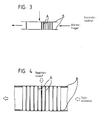
- the short-tube reactor according to the invention shown schematically in FIG. 3, has a series of reaction tubes A which are fastened between two tube plates B. Between the tube sheets B, a heat transfer medium flows in a direction substantially perpendicular to the longitudinal axis of the reaction tube and flows around the reaction tubes A.
- the direction of flow of the heat transfer medium which is preferably a molten salt, is indicated in FIG. 3 by the arrows pointing to the left.
- the reaction stream is indicated by the arrow pointing downwards.
- the reaction flow takes place through the reaction tubes.
- the reaction tubes are expediently arranged offset from one another.
- FIG. 4 A sectional view through a short tube reactor according to the invention is partially shown in FIG.
- the reaction tubes are designated A in FIG. 4 and the tube sheets are designated B.
- the embodiment shown in FIG. 4 has a reaction tube inside diameter of preferably 10 to 15 mm and a tube length of preferably 50 to 200 mm.
- the tubes are welded into the tube sheets using automatic machines.
- Figure 5 shows a tube plate in a top view.
- the tube sheet B is provided with openings in which the reaction tubes are inserted. It can be seen that the construction of the short tube reactor according to the invention is very simple. This affects the manufacturing costs. Especially when pressure-free the short tube reactor can be manufactured particularly inexpensively with little material.
- the heat transfer medium preferably a molten salt, flows in the transverse direction onto the reaction tubes. This results in a uniform inflow over the pipe length.
- the temperature distribution in the reaction tube can be set in a defined manner with the aid of the salt temperature. An optimal yield of valuable product can thus always be achieved with a variable composition of the reactor feed.
- the use of inert gases can be greatly reduced.
- the short-tube reactor according to the invention is particularly suitable for the continuous implementation of catalytically accelerated reactions which are highly exothermic and whose reaction rate is strongly dependent on the temperature. Examples of such reactions are: oxidations, in particular oxidative dehydrogenations and halogenations.
- the short tube reactor is particularly suitable for the production of aliphatic, aromatic and araliphatic ketones and aldehydes by oxidative dehydrogenation of corresponding alcohols in the presence of a catalyst from group 1b of the periodic table of the elements.
- Alcohols of the general formula II ⁇ come as starting products into consideration where R1 and R2 are the same or different and represent hydrogen or a saturated or unsaturated, branched or unbranched aliphatic radical, preferably having 1 to 20, in particular 1 to 12, carbon atoms, moreover a mono- or polysubstituted aryl, preferably phenyl, which, if substituted, is preferably substituted 1 or 2 times, in particular by C1 to C5-alkyl radicals and C1-to C5-alkoxy radical, or where R1 and R2 can also be an aralkyl radical.
- Examples of possible starting materials of the general formula II ⁇ are: methanol, ethanol, propanol, isopropanol, n-butanol, iso-butanol, sec-butanol, n-pentanol, 2-pentanol, 3-pentanol, 2-methylbutanol, 3-methylbutanol, hexanol, 2-hexanol, 3-hexanol, 2-methylhexanol, 3-methylhexanol, 2-ethylhexanol, heptanol, 2-heptanol, but-2-en-1-ol, but-3-en-1- ol, 2-methyl-but-3-en-1-ol, 3-methyl-but-3-en-1-ol, pent-3-en-1-ol, hex-2-en-1-ol, Octen-1-en-3-o, 2-methylbenzyl alcohol, 3-methylbenzyl alcohol, 4-methylbenzyl alcohol, 2-methoxybenzy
- -Butyl group are substituted twice; o-, m- and p-hydroxymethyl-benzyl alcohol and corresponding di- (hydroxymethyl) -benzenes substituted in the aforementioned manner on the nucleus; unsubstituted or substituted in the aforementioned manner phenylethyl, phenylpropyl, phenylisopropyl, phenylbutyl, phenyl sec-butyl, phenyl tert-butyl, phenylsiobutyl, phenylpentyl, phenylhexyl, phenylisopentyl alcohols.
- alcohol of the general formula II or alcohol of the general formula II ⁇ is fed to the reaction space together with a solvent in vapor form and advantageously in a mixture with inert gas.
- Tetrahydrofuran, dioxane, toluene or H2O are advantageously used as solvents which are inert under the reaction conditions.
- the ratio of solvent to alcohol is advantageously 0 to 1: 1.
- Both inert gases, but preferably nitrogen, carbon oxide and / or carbon dioxide, can be used as the inert gas.
- the molar ratio of inert gas to oxygen is at least 4.4: 1, expediently 4.4 to 20: 1, the information regarding inert gas always relating to the total amount, i.e. the inert gas portion of the air preferably used.
- Oxygen usually in the form of air and alcohol, is expediently used in a molar ratio of 0.1 to 0.5, in particular 0.15 to 0.35, mol of oxygen per mol of alcohol.
- the residence time of the gas mixture in the reaction space is 0.0005 to 1, preferably 0.001 to 0.05 seconds. Because of the short residence time, side reactions are almost completely suppressed.
- the reaction tubes are charged with the catalyst in the tube bundle reactor according to the invention.
- the layer thickness of the catalyst is advantageously 10 to 150, preferably 20 to 80 mm.
- the catalyst particles are layered, for example, on a mesh of silver or stainless steel in the vertically placed reactor. Particles with a grain size of 0.1 to 5 mm are suitable as catalyst particles.
- the service life of the catalyst with constant activity and selectivity is 3 months and more.
- the catalyst is expediently loaded with 0.2 to 2 t, in particular 0.3 to 1.5 t, of alcohol per m2 of catalyst cross section and hour.
- the gas mixture of alcohol, air and inert gas is passed through the catalyst in the amounts mentioned at temperatures of 300 to 600 ° C., preferably at 380 to 520 ° C.
- the reaction is generally carried out continuously at pressures between 0.8 to 2 bar, preferably 1.05 to 1.5 bar.
- reaction gases emerging from the reactor are rapidly co-cooled with the product mixture or an inert solvent or the product-containing solvent mixture to room temperature and condensed.
- Suitable solvents are water or a water-forming solvent from the class of hydrocarbons, substituted hydrocarbons or ethers, such as hexane, toluene or methyl tert-butyl ether.
- the mixture is passed together with the reaction gases over a column filled with glass rings to completely dissolve the products in the solvent.
- the condensable components can be obtained completely.
- the invention is further illustrated by the following examples and comparative examples.
- a system with feeds for air (1) and educt vapor (2) is used on a short tube bundle reactor (3).
- the contact tubes are 60 mm high with silver catalysts with a grain size of 0.4 to 0.7 mm.
- a molten salt (4) flows around the contact tubes for heat dissipation.
- the hot reaction gases are cooled in a quench with a subsequent column (5), which is charged with the water phase (6) of the product discharge.
- the two liquid phases of the discharge are taken up for working up via line (8) or (7);
- the gaseous components are disposed of via line (9).
- Example 2 a silver fraction with a grain size of 1.0-2.5 mm and a bed height of 100 mm is used instead of the fine silver catalyst. If 44 Nl of air, 113 g of 3-methyl-3-buten-1-ol vapor and 21.5 g of steam per hour and tube are fed to the reactor, the catalyst temperature is 440 ° C. (salt bath temperature 385 ° C.) ) 520 g of unreacted 3-methyl-3-buten-1-ol and 53.6 g of 3-methyl-2-buten-al corresponding to a conversion of 3-methyl-3-buten-1-ol of 54% and one 90% selectivity.
- the catalyst temperature is 440 ° C. (salt bath temperature 385 ° C.) ) 520 g of unreacted 3-methyl-3-buten-1-ol and 53.6 g of 3-methyl-2-buten-al corresponding to a conversion of 3-methyl-3-buten-1-ol of 54% and one 90% selectivity.
- 3-buten-1-ol is converted to 3-buten-al in a laboratory apparatus which consists only of a tube cooled by a salt bath.
- Example 4 65.3 g of 4-pentan-1-ol are reacted with 20.3 Nl of air per hour at 440 ° C. (salt temperature 390 ° C.). 28.7 g are obtained unreacted 4-penten-1-ol and 32.4 g of 4-pentenal, corresponding to a conversion of 66% and a selectivity of 77%.
- a system with feeds for air (1) and educt vapor (2) is used on a crucible reactor.
- the crucible has a diameter of 20 mm.
- the crucible contains a silver catalyst layer of the following composition (seen in the direction of flow):
- reaction gases leaving the reactor are treated as described in Example 1.
- a system according to FIG. 7 is used with a feed for air (1) and educt vapor (2) onto a crucible reactor (3).
- the crucible has a diameter of 800 mm.
- the perforated bottom is covered with a stainless steel net.
- 3-buten-1-ol is converted to 3-butenal.
- 55.9 Nl of air and 151 g of 3-buten-1-ol per hour at a reaction temperature of 510 ° C 10.6 g of unreacted 3-buten-1-ol and 20.5 g of 3-butenal are obtained from the discharge corresponding to a conversion of 3-buten-1-ol of 93% and a selectivity of 15%.
Landscapes
- Chemical & Material Sciences (AREA)
- Organic Chemistry (AREA)
- Chemical Kinetics & Catalysis (AREA)
- Organic Low-Molecular-Weight Compounds And Preparation Thereof (AREA)
- Low-Molecular Organic Synthesis Reactions Using Catalysts (AREA)
- Devices And Processes Conducted In The Presence Of Fluids And Solid Particles (AREA)
Abstract
Description
Die Erfindung betrifft einen Rohrbündelreaktor zur Durchführung organischer Reaktionen in der Gasphase mit zwischen Rohrböden angeordneten Reaktionsrohren. Die Erfindung betrifft ferner die Verwendung des Rohrbündelreaktors bei exothermen organischen Reaktionen. Gegenstand der Erfindung ist auch ein Verfahren zur Herstellung aliphatischer, aromatischer oder araliphatischer Ketone und Aldehyde unter Verwendung des erfindungsgemäßen Rohrbündelreaktors. Der erfindungsgemäße Rohrbündelreaktor ist besonders geeignet zur Durchführung katalytisch beschleunigter Reaktionen, die stark exotherm sind und deren Reaktionsgeschwindigkeit stark von der Temperatur abhängt.The invention relates to a tube bundle reactor for carrying out organic reactions in the gas phase with reaction tubes arranged between tube sheets. The invention further relates to the use of the tube bundle reactor in exothermic organic reactions. The invention also relates to a process for the preparation of aliphatic, aromatic or araliphatic ketones and aldehydes using the tube bundle reactor according to the invention. The tube bundle reactor according to the invention is particularly suitable for carrying out catalytically accelerated reactions which are highly exothermic and the rate of which depends strongly on the temperature.
Wenn die Stabilität von Reaktanden und Produkten dies gestattet, kann man derartige Reaktionen adiabatisch bei extrem kurzen Verweilzeiten durchführen. Beispiele sind die Ammonoxidation an Platinnetzen oder die oxidative Dehydrierung von Methanol zu Formaldehyd an einer Schüttung von Silberkristallen von ca. 20 mm Höhe.If the stability of reactants and products allows this, such reactions can be carried out adiabatically with extremely short residence times. Examples are the ammoxidation on platinum nets or the oxidative dehydrogenation of methanol to formaldehyde on a bed of silver crystals with a height of approx. 20 mm.
Sind die Reaktanden oder Produkte instabil, so daß eine adiabatische Reaktionsführung nicht möglich ist, so muß über eine Wärmetauschfläche zumindest ein Teil der Reaktionswärme abgeführt werden. Man kann den Katalysator entweder zwischen (Linde-Reaktor: DE-A-34 14 717) oder in (Rohrbündelreaktor: Chemie Ingenieur Technik 51 (79) S. 257-265) die Rohre eines Wärmetauschers einbringen. Reaktoren dieser Art besitzen Rohre von mehreren Zentimetern Durchmesser und Längen von 2 bis 20 Metern, d.h. sie haben relativ lange Verweilzeiten. Bei stark exothermen Reaktionen bildet sich ein hot spot aus, der häufig zu erheblichen Selektivitätsverlusten oder Schädigungen des Kontaktes führt. Man kann versuchen, den hot spot dadurch zu beseitigen, daß der Katalysator am Beginn der Schüttung mit inertem Material verdünnt wird, oder daß man bei partiellem Umsatz fährt und Kreisgas in den Reaktor zurückführt. Dies erzwingt einen großen technischen Aufwand, nämlich große Reaktoren, eine umfangreiche Abgasaufarbeitung und die Bewältigung großer Kreisgasmengen, und dennoch sind häufig Selektivitätsverluste nicht zu vermeiden.If the reactants or products are unstable, so that an adiabatic reaction is not possible, at least some of the heat of reaction must be removed via a heat exchange surface. You can either insert the catalyst between (Linde reactor: DE-A-34 14 717) or in (tube bundle reactor: chemical engineer technology 51 (79) pp. 257-265) the tubes of a heat exchanger. Reactors of this type have tubes of several centimeters in diameter and lengths of 2 to 20 meters, i.e. they have relatively long dwell times. In the case of strongly exothermic reactions, a hot spot forms, which often leads to considerable loss of selectivity or damage to the contact. One can try to eliminate the hot spot by diluting the catalyst with inert material at the beginning of the bed, or by driving at partial conversion and recycle gas into the reactor. This requires a great deal of technical effort, namely large reactors, extensive exhaust gas processing and coping with large amounts of circulating gas, and yet selectivity losses are often unavoidable.
Wenn zur thermischen Instabilität von Reaktanden und Produkten eine große Reaktionswärme und eine hohe Aktivierungsenergie hinzukommen, so ist ein Reaktor erforderlich, der einerseits die sehr kleine Verweilzeit des adiabatischen Reaktors mit einer kurzen Katalysatorschüttung und andererseits mindestens die gute Wärmeabfuhr des Rohrbündelreaktors vereinigt.If a large heat of reaction and a high activation energy are added to the thermal instability of reactants and products, a reactor is required which combines the very short residence time of the adiabatic reactor with a short catalyst bed and at least the good heat dissipation of the tube bundle reactor.
Die EP-A-55 354 beschreibt ein katalytisches Verfahren zur kontinuierlichen Herstellung von 3-Alkyl-buten-1-alen durch oxidierende Dehydrierung der entsprechenden Alkohole in einem Rohrreaktor. Der Rohrreaktor ist ersichtlich von üblicher Bauart, über Rohrabmessungen und sonstige konstruktive Ausgestaltungen ist in der Druckschrift nichts gesagt, da es nach der bekannten Lehre darauf auch offensichtlich nicht ankommt.EP-A-55 354 describes a catalytic process for the continuous production of 3-alkyl-buten-1-alene by oxidizing dehydrogenation of the corresponding alcohols in a tubular reactor. The tube reactor is of a conventional design, nothing is said in the document about tube dimensions and other constructive configurations, since, according to the known teaching, it obviously does not matter.
Der Erfindung liegt die Aufgabe zugrunde, einen Rohrbündelreaktor der eingangs genannten Art so auszugestalten, daß bei stark exothermen Reaktionen, insbesondere an extrem aktiven Katalysatoren, beispielsweise an Edelmetallkontakten, in der Gasphase eine wohl definierte Reaktionsführung möglich ist. Insbesondere sollen bei derartigen Reaktionen hohe Selektivitäten erzielt werden.The invention is based on the object of designing a tube-bundle reactor of the type mentioned at the outset such that well-defined reaction control is possible in the gas phase in the case of strongly exothermic reactions, in particular on extremely active catalysts, for example on noble metal contacts. In particular, high selectivities should be achieved in such reactions.
Diese Aufgabe wird gelöst mit einem Rohrbündelreaktor der eingangs genannten Art, der dadurch gekennzeichnet ist, daß die Reaktionsrohre einen Innendurchmesser im Bereich von 0,5 bis 3 cm aufweisen, das Verhältnis Reaktionsrohrlänge zu Innendurchmesser zwischen 2 und 10 liegt und daß die Reaktionsrohre von einem fluiden Wärmeträger in seitlicher Richtung umströmt werden.This object is achieved with a tube bundle reactor of the type mentioned at the outset, which is characterized in that the reaction tubes have an inside diameter in the range from 0.5 to 3 cm, the ratio of the reaction tube length to the inside diameter is between 2 and 10 and that the reaction tubes are of a fluid Flow around heat transfer medium in the lateral direction.
Nach einer bevorzugten Ausführungsform weisen die Reaktionsrohre eine Länge von 5 bis 20 cm auf.According to a preferred embodiment, the reaction tubes have a length of 5 to 20 cm.
Besonders bevorzugt ist ein Rohrinnendurchmesser von 1 bis 2 cm.A tube inside diameter of 1 to 2 cm is particularly preferred.
Als fluider Wärmeträger kommen die üblichen Wärmeträger in Betracht, besonders bevorzugt sind Salzschmelzen. Die Strömungsrichtung des fluiden Wärmeträgers verläuft im wesentlichen senkrecht zur Längsachse des jeweiligen Reaktionsrohrs.The usual heat carriers come into consideration as fluid heat carriers; molten salts are particularly preferred. The direction of flow of the fluid heat transfer medium is essentially perpendicular to the longitudinal axis of the respective reaction tube.
Mit Hilfe des erfindungsgemäßen Kurzrohrbündelreaktors läßt sich eine extrem hohe und gleichmäßige Anströmung der Rohre und damit eine besonders große Wärmeabfuhr erzielen. Die kompakte Bauweise erlaubt zudem eine einfache Führung des Wärmeträgers und führt zu einem preiswerten Reaktor mit hoher Raum-Zeit-Ausbeute. Darüber hinaus müssen über die Bedürfnisse des speziellen chemischen Prozesses hinausgehende Inertgasmengen nicht oder nur in geringfügigem Maße zugefahren werden.With the help of the short tube bundle reactor according to the invention, an extremely high and uniform flow against the tubes and thus a particularly large heat dissipation can be achieved. The compact design also allows easy management of the heat transfer medium and leads to an inexpensive reactor with a high space-time yield. In addition, quantities of inert gas that go beyond the needs of the special chemical process do not have to be added or only to a small extent.
Während bei den bekannten Rohrbündelreaktoren das Verhältnis Rohrlänge zu Rohrdurchmesser bei 100 bis 1000 liegt, liegt dieses Verhältnis beim erfindungsgemäßen Kurzrohrbündelreaktor im Bereich von 2 bis 10. Durch die kurzen Rohre erhält ein technischer Reaktor die Form einer flachen Scheibe mit relativ kleinem Volumen. Bei dieser Reaktorform braucht der Wärmeträger nicht in einem großen, dreidimensionalen Raum verteilt werden.While in the known tube bundle reactors the ratio of tube length to tube diameter is 100 to 1000, this ratio for the short tube bundle reactor according to the invention is in the range of 2 to 10. The short tubes give a technical reactor the shape of a flat disk with a relatively small volume. With this type of reactor, the heat transfer medium does not need to be distributed in a large, three-dimensional space.
Gegenstand der Erfindung ist auch die Verwendung des erfindungsgemäßen Rohrbündelreaktors bei exothermen organischem Reaktionen. Insbesondere ist weiterer Gegenstand der Erfindung ein Verfahren zur Herstellung aliphatischer, aromatischer oder araliphatischer Ketone und Aldehyde durch oxidierende Dehydrierung der entsprechenden Alkohole mit einem Katalysator der Gruppe 1b des Periodensystems der Elemente. Dieses Verfahren ist dadurch gekennzeichnet, daß man die oxidierende Dehydrierung in einem wie zuvor definierten Rohrbündelreaktor durchführt.The invention also relates to the use of the tube bundle reactor according to the invention in exothermic organic reactions. In particular, the invention further relates to a process for the preparation of aliphatic, aromatic or araliphatic ketones and aldehydes by oxidizing dehydrogenation of the corresponding alcohols with a catalyst from group 1b of the periodic table of the elements. This process is characterized in that the oxidizing dehydrogenation is carried out in a tube bundle reactor as defined above.
Eine besonders vorteilhafte Ausgestaltung des erfindungsgemäßen Verfahrens dient zur Herstellung von 3-Alkyl-buten-1-alen der allgemeinen Formel I


Unter Verwendung des erfindungsgemäßen Rohrbündelreaktors erhält man die gewünschten Wertprodukte mit hohen Selektivitäten und Umsätzen.Using the tube bundle reactor according to the invention, the desired products of value are obtained with high selectivities and conversions.
Die Erfindung und der Stand der Technik sind in den Figuren 1 bis 7 der Zeichnungen näher erläutert. In der Zeichnung bedeuten:
Figur 1 einen Querschnitt durch einen schematisch dargestellten Längsstromreaktor des Standes der Technik;Figur 2 einen Querschnitt durch einen schematisch dargestellten Radialstromreaktor des Standes der Technik;- Figur 3 einen Querschnitt durch eine schematische Darstellung eines erfindungsgemäßen Kurzrohrreaktors;
Figur 4 einen Ausschnitt aus dem Kurzrohrreaktor der Figur 3;Figur 5 eine Aufsicht auf einen Teil des Kurzrohrreaktors gemäßFigur 4;Figur 6 eine Anlage zur Durchführung exothermer organischer Reaktionen, insbesondere zur oxidativen Dehydrierung von Ketonen und Aldehyden unter Verwendung eines erfindungsgemäßen Rohrbündelreaktors; undFigur 7 eine nicht erfindungsgemäße Anlage zur Durchführung derselben Reaktion mit einen Tiegelreaktor (Vergleichsbeispiele 1 bis 4).
- 1 shows a cross section through a schematically illustrated longitudinal flow reactor of the prior art;
- Figure 2 shows a cross section through a schematically illustrated radial flow reactor of the prior art;
- Figure 3 shows a cross section through a schematic representation of a short tube reactor according to the invention;
- FIG. 4 shows a detail from the short tube reactor of FIG. 3;
- FIG. 5 shows a plan view of a part of the short tube reactor according to FIG. 4;
- FIG. 6 shows a plant for carrying out exothermic organic reactions, in particular for the oxidative dehydrogenation of ketones and aldehydes using a tube bundle reactor according to the invention; and
- Figure 7 shows a system according to the invention for carrying out the same reaction with a crucible reactor (comparative examples 1 to 4).
Beim Längsstromreaktor des Standes der Technik gemäß Figur 1 werden die Reaktionsrohre parallel zur Längsachse des jeweiligen Reaktionsrohrs gleichmäßig mit einem Salzstrom angeströmt. Nachteilig an dem Längsstromreaktor ist, daß der salzseitige Wärmeübergangskoeffizient infolge der Längsanströmung relativ gering ist.In the longitudinal flow reactor of the prior art according to FIG. 1, a parallel flow of salt flows onto the reaction tubes parallel to the longitudinal axis of the respective reaction tube. A disadvantage of the longitudinal flow reactor is that the heat transfer coefficient on the salt side is relatively low due to the longitudinal flow.
Die Queranströmung der Rohre beim Radialstromreaktor gemäß Figur 2 führt zwar zu einem deutlich höheren Wärmeübergangskoeffizienten auf der Salzseite, jedoch sind Umlenkungen des Salzstromes erforderlich. Um eine ungleichmäßige Anströmung der Rohre zu vermeiden, kann nur ein Ringraum mit Reaktionsrohren bestückt werden.The transverse flow of the tubes in the radial flow reactor according to FIG. 2 leads to a significantly higher heat transfer coefficient on the salt side, but deflections of the salt flow are necessary. In order to avoid an uneven flow to the tubes, only one annulus can be equipped with reaction tubes.
Der in Figur 3 schematisch dargestellte erfindungsgemäße Kurzrohrreaktor weist eine Reihe von Reaktionsrohren A auf, die zwischen 2 Rohrböden B befestigt sind. Zwischen den Rohrböden B strömt in einer zur Reaktionsrohrlängsachse im wesentlichen senkrechten Richtung ein Wärmeträger und umströmt die Reaktionsrohre A. Die Strömungsrichtung des Wärmeträgers, bei dem es sich vorzugsweise um eine Salzschmelze handelt, ist in der Figur 3 durch die nach links weisenden Pfeile angedeutet. Der Reaktionsstrom ist durch den nach unten deutenden Pfeil bezeichnet. Der Reaktionsstrom erfolgt durch die Reaktionsrohre. Die Reaktionsrohre sind zweckmäßig zueinander versetzt angeordnet.The short-tube reactor according to the invention, shown schematically in FIG. 3, has a series of reaction tubes A which are fastened between two tube plates B. Between the tube sheets B, a heat transfer medium flows in a direction substantially perpendicular to the longitudinal axis of the reaction tube and flows around the reaction tubes A. The direction of flow of the heat transfer medium, which is preferably a molten salt, is indicated in FIG. 3 by the arrows pointing to the left. The reaction stream is indicated by the arrow pointing downwards. The reaction flow takes place through the reaction tubes. The reaction tubes are expediently arranged offset from one another.
In der Figur 4 ist eine Schnittansicht durch einen erfindungsgemäßen Kurzrohrreaktor teilweise dargestellt. Ebenso wie in der Figur 3 sind in der Figur 4 die Reaktionsrohre mit A und die Rohrböden mit B bezeichnet. Die in der Figur 4 dargestellte Ausführungsform weist einen Reaktionsrohrinnendurchmesser von vorzugsweise 10 bis 15 mm und eine Rohrlänge von vorzugsweise 50 bis 200 mm auf. Die Rohre werden mit Hilfe von Automaten in die Rohrböden geschweißt. In der Figure 5 ist ein Rohrboden in der Aufsicht zu sehen. Der Rohrboden B ist mit Öffnungen versehen, in welche die Reaktionsrohre eingesetzt sind. Es ist ersichtlich, daß die Konstruktion des erfindungsgemäßen Kurzrohrreaktors sehr einfach ist. Das wirkt sich in den Fertigungskosten aus. Insbesondere bei druckloser Ausführung läßt sich der Kurzrohrreaktor mit geringem Materialaufwand besonders kostengünstig fertigen.A sectional view through a short tube reactor according to the invention is partially shown in FIG. As in FIG. 3, the reaction tubes are designated A in FIG. 4 and the tube sheets are designated B. The embodiment shown in FIG. 4 has a reaction tube inside diameter of preferably 10 to 15 mm and a tube length of preferably 50 to 200 mm. The tubes are welded into the tube sheets using automatic machines. Figure 5 shows a tube plate in a top view. The tube sheet B is provided with openings in which the reaction tubes are inserted. It can be seen that the construction of the short tube reactor according to the invention is very simple. This affects the manufacturing costs. Especially when pressure-free the short tube reactor can be manufactured particularly inexpensively with little material.
Die Reaktionsrohre werden vom Wärmeträger, vorzugsweise einer Salzschmelze, in Querrichtung angeströmt. Hierdurch ergibt sich über die Rohrlänge eine gleichmäßige Anströmung. Infolge der sehr hohen spezifischen Kühlfläche läßt sich die Temperaturverteilung im Reaktionsrohr mit Hilfe der Salztemperatur definiert einstellen. Man kann somit bei variabler Zusammensetzung des Reaktorzulaufes stets eine optimale Ausbeute an Wertprodukt erzielen. Bei den vorzugsweise eingesetzten Edelmetallkatalysatoren kann der Einsatz von Inertgasen stark reduziert werden.The heat transfer medium, preferably a molten salt, flows in the transverse direction onto the reaction tubes. This results in a uniform inflow over the pipe length. As a result of the very high specific cooling surface, the temperature distribution in the reaction tube can be set in a defined manner with the aid of the salt temperature. An optimal yield of valuable product can thus always be achieved with a variable composition of the reactor feed. In the case of the noble metal catalysts which are preferably used, the use of inert gases can be greatly reduced.
Im Vergleich zum Stand der Technik ergeben sich beim erfindungsgemäßen Rohrbündelreaktor insbesondere die folgenden Vorteile:
- 1. Stark exotherme organische Reaktionen, vorzugsweise an Edelmetallkontakten, können bei definierten Temperaturen durchgeführt werden. Eine flexible Anpassung der Reaktionsbedingungen an die jeweiligen Reaktanden ist möglich.
- 2. Der erfindungsgemäße Kurzrohrreaktor erlaubt eine sehr gleichmäßige Queranströmung aller Rohre. Hieraus resultiert eine sehr kompakte Bauweise mit maximalen Wärmeübergangskoeffizienten.
- 3. Selbst bei Verwendung von feinkörnigem Katalysatormaterial in den Reaktionsrohren ist der Druckabfall in den Rohren gering. Verwendet man poröse Katalysatoren, ergeben sich auf einfache Weise kurze Diffusionswege in den Poren des Katalysators.
- 1. Strongly exothermic organic reactions, preferably on precious metal contacts, can be carried out at defined temperatures. A flexible adaptation of the reaction conditions to the respective reactants is possible.
- 2. The short tube reactor according to the invention allows a very uniform cross-flow to all tubes. This results in a very compact design with maximum heat transfer coefficients.
- 3. Even if fine-grained catalyst material is used in the reaction tubes, the pressure drop in the tubes is low. If porous catalysts are used, short diffusion paths in the pores of the catalyst result in a simple manner.
Der erfindungsgemäße Kurzrohrreaktor eignet sich insbesondere zur kontinuierlichen Durchführung von katalytisch beschleunigten Reaktionen, die stark exotherm sind und deren Reaktionsgeschwindigkeit stark von der Temperatur abhängt. Als solche Reaktionen kommen beispielsweise in Frage: Oxidationen, insbesondere oxidative Dehydrierungen und Halogenierungen.The short-tube reactor according to the invention is particularly suitable for the continuous implementation of catalytically accelerated reactions which are highly exothermic and whose reaction rate is strongly dependent on the temperature. Examples of such reactions are: oxidations, in particular oxidative dehydrogenations and halogenations.
Der Kurzrohrreaktor eignet sich insbesondere zur Herstellung von aliphatischen, aromatischen und araliphatischen Ketonen und Aldehyden durch oxidative Dehydrierung von entsprechenden Alkoholen in Gegenwart eines Katalysators der Gruppe 1b des Periodensystems der Elemente.The short tube reactor is particularly suitable for the production of aliphatic, aromatic and araliphatic ketones and aldehydes by oxidative dehydrogenation of corresponding alcohols in the presence of a catalyst from group 1b of the periodic table of the elements.
Als Ausgangsprodukte kommen Alkohole der allgemeinen Formel IIʹ

wobei R¹ und R² gleich oder verschieden sind und für Wasserstoff oder einen gesättigten oder ungesättigten, verzweigten oder unverzweigten aliphatischen Rest, vorzugsweise mit 1 bis 20, insbesondere 1 bis 12 Kohlenstoffatomen, darüber hinaus für einen ein- oder mehrfach substituierten Aryl-, vorzugsweise Phenylrest, der, wenn er substituiert ist, vorzugsweise 1- oder 2-mal, insbesondere durch C₁- bis C₅-Alkylreste und C₁-bis C₅-Alkoxyrest substituiert ist, oder wobei R¹ und R² auch für einen Aralkylrest stehen können.Alcohols of the general formula IIʹ come as starting products
where R¹ and R² are the same or different and represent hydrogen or a saturated or unsaturated, branched or unbranched aliphatic radical, preferably having 1 to 20, in particular 1 to 12, carbon atoms, moreover a mono- or polysubstituted aryl, preferably phenyl, which, if substituted, is preferably substituted 1 or 2 times, in particular by C₁ to C₅-alkyl radicals and C₁-to C₅-alkoxy radical, or where R¹ and R² can also be an aralkyl radical.
Es kommen z.B. als Ausgangsstoffe der allgemeinen Formel IIʹ in Frage: Methanol, Ethanol, Propanol, iso-Propanol, n-Butanol, iso-Butanol, sek.Butanol, n-Pentanol, 2-Pentanol, 3-Pentanol, 2-Methylbutanol, 3-Methylbutanol, Hexanol, 2-Hexanol, 3-Hexanol, 2-Methylhexanol, 3-Methylhexanol, 2-Ethylhexanol, Heptanol, 2-Heptanol, But-2-en-1-ol, But-3-en-1-ol, 2-Methyl-but-3-en-1-ol, 3-Methyl-but-3-en-1-ol, Pent-3-en-1-ol, Hex-2-en-1-ol, Octen-1-en-3-o, 2-Methylbenzylalkohol, 3-Methylbenzylalkohol, 4-Methylbenzylalkohol, 2-Methoxybenzylalkohol, 3-Methoxybenzylalkohol, 4-Methoxybenzylalkohol, 2,3-Dimethylbenzylalkohol, 3,4-Dimethylbenzylalkohol, 2,6-Dimethylbenzylalkohol, 3,5-Dimethylbenzylalkohol, 2,3-Dimethoxybenzylalkohol, 3,4-Dimethoxybenzylalkohol, 3,5-Dimethoxybenzylalkohol, 2-Ethylbenzylalkohol, 3-Ethylbenzylalkohol, 4-Ethylbenzylalkohol, 2,3-Diethylbenzylalkohol, 3,4-Diethylbenzylalkohol, 2,6-Diethylbenzylalkohol, 3,5-Diethylbenzylalkohol, 2-Ethoxybenzylalkohol, 3-Ethoxybenzylalkohol, 4-Ethoxybenzylalkohol, 2-n-Propylbenzylalkohol, 3-n-Propylbenzylalkohol, 4-n-Propylbenzylalkohol, 2,3-Di-n-propylbenzylalkohol, 3,4-Di-n-propylbenzylalkohol, 2,6-Di-n-propylbenzylalkohol, 3,5-Di-n-propylbenzylalkohol, 2-Isopropylbenzylalkohol, 3-Isopropylbenzylalkohol, 4-Isopropylbenzylalkohol, 2-Butylbenzylalkohol, 3-Butylbenzylalkohol, 4-Butylbenzylalkohol, 2-Isobutylbenzylalkohol, 3-Isobutylbenzylalkohol, 4-Isobutylbenzylalkohol, 2-tert.-Butylbenzylalkohol, 3-tert.-Butylbenzylalkohol, 4-tert.-Butylbenzylalkohol, 2,3-Diethoxybenzylalkohol, 3,4-Diethoxybenzylalkohol, 2,6-Diethoxybenzylalkohol, 3,5-Diethoxybenzylalkohol, Benzylalkohol; 2,3,4-Trimethoxybenzylalkohol, 3,4,5-Trimethoxybenzylalkohol, 2,4,6-Trimethoxybenzylalkohol und entsprechende durch die Ethyl-, n-Propyl-, Isopropyl-, n-Butyl-, sek.-Butyl-, Isobutyl-, tert.- Butylgruppe veretherte Trihydroxybenzylalkohole; unsubstituierte oder in vorgenannter Weise substituierte o-, m-oder p-Aminobenzylalkohole, deren Stickstoffatome durch die Methyl-, Ethyl-, n-Propyl-, Isopropyl-, n-Butyl-, sek.-Butyl-, Isobutyl-, tert.-Butylgruppe zweifach substituiert sind; o-, m- und p-Hydroxymethyl-benzylalkohol und entsprechende, in vorgenannter Weise am Kern substituierte Di-(hydroxymethyl)-benzole; unsubstituierte oder in vorgenannter Weise substituierte Phenylethyl-, Phenylpropyl-, Phenylisopropyl-, Phenylbutyl-, Phenyl-sek.-butyl-, Phenyltert.-butyl-, Phenylsiobutyl-, Phenylpentyl-, Phenylhexyl-, Phenylisopentylalkohole.Examples of possible starting materials of the general formula IIʹ are: methanol, ethanol, propanol, isopropanol, n-butanol, iso-butanol, sec-butanol, n-pentanol, 2-pentanol, 3-pentanol, 2-methylbutanol, 3-methylbutanol, hexanol, 2-hexanol, 3-hexanol, 2-methylhexanol, 3-methylhexanol, 2-ethylhexanol, heptanol, 2-heptanol, but-2-en-1-ol, but-3-en-1- ol, 2-methyl-but-3-en-1-ol, 3-methyl-but-3-en-1-ol, pent-3-en-1-ol, hex-2-en-1-ol, Octen-1-en-3-o, 2-methylbenzyl alcohol, 3-methylbenzyl alcohol, 4-methylbenzyl alcohol, 2-methoxybenzyl alcohol, 3-methoxybenzyl alcohol, 4-methoxybenzyl alcohol, 2,3-dimethylbenzyl alcohol, 3,4-dimethylbenzyl alcohol, 2,6- Dimethylbenzyl alcohol, 3,5-dimethylbenzyl alcohol, 2,3-dimethoxybenzyl alcohol, 3,4-dimethoxybenzyl alcohol, 3,5-dimethoxybenzyl alcohol, 2-ethylbenzyl alcohol, 3-ethylbenzyl alcohol, 4-ethylbenzyl alcohol, 2,3-diethylbenzyl alcohol, 3,4-diethylbenzyl 2,6-diethylbenzyl alcohol, 3,5-diethylbenzyl alcohol, 2-ethoxybenzyl alcohol, 3-ethoxybenzyl alcohol, 4-Et hoxybenzyl alcohol, 2-n-propylbenzyl alcohol, 3-n-propylbenzyl alcohol, 4-n-propylbenzyl alcohol, 2,3-di-n-propylbenzyl alcohol, 3,4-di-n-propylbenzyl alcohol, 2,6-di-n-propylbenzyl alcohol, 3,5-di-n-propylbenzyl alcohol, 2-isopropylbenzyl alcohol, 3-isopropylbenzyl alcohol, 4-isopropylbenzyl alcohol, 2-butylbenzyl alcohol, 3-butylbenzyl alcohol, 4-butylbenzyl alcohol, 2-isobutylbenzyl alcohol, 3-isobutylbenzyl alcohol, 3-isobutylbenzyl alcohol, 3-isobutyl benzyl alcohol. -Butylbenzyl alcohol, 3-tert-butylbenzyl alcohol, 4-tert-butylbenzyl alcohol, 2,3-diethoxybenzyl alcohol, 3,4-diethoxybenzyl alcohol, 2,6-diethoxybenzyl alcohol, 3,5-diethoxybenzyl alcohol, benzyl alcohol; 2,3,4-trimethoxybenzyl alcohol, 3,4,5-trimethoxybenzyl alcohol, 2,4,6-trimethoxybenzyl alcohol and corresponding ones by the ethyl, n-propyl, isopropyl, n-butyl, sec-butyl, isobutyl -, tert.- Trihydroxybenzyl alcohols etherified by butyl group; unsubstituted or substituted in the aforementioned manner, o-, m- or p-aminobenzyl alcohols, the nitrogen atoms of which are substituted by the methyl, ethyl, n-propyl, isopropyl, n-butyl, sec-butyl, isobutyl, tert. -Butyl group are substituted twice; o-, m- and p-hydroxymethyl-benzyl alcohol and corresponding di- (hydroxymethyl) -benzenes substituted in the aforementioned manner on the nucleus; unsubstituted or substituted in the aforementioned manner phenylethyl, phenylpropyl, phenylisopropyl, phenylbutyl, phenyl sec-butyl, phenyl tert-butyl, phenylsiobutyl, phenylpentyl, phenylhexyl, phenylisopentyl alcohols.
Für die Umsetzung wird Alkohol der allgemeinen Formel II oder Alkohol der allgemeinen Formel IIʹ zusammen mit einem Lösemittel in Dampfform und vorteilhaft im Gemisch mit Inertgas dem Reaktionsraum zugeführt. Als unter Reaktionsbedingungen inerte Lösemittel werden zweckmäßig Tetrahydrofuran, Dioxan, Toluol oder H₂O verwendet. Das Verhältnis Lösemittel zu Alkohol beträgt vorteilhaft 0 bis 1:1. Als Inertgas können sowohl Edelgase, bevorzugt jedoch Stickstoff, Kohlenoxid und/oder Kohlendioxid, verwendet werden. Das Molverhältnis von Inertgas zu Sauerstoff beträgt mindestens 4,4:1, zweckmäßig 4,4 bis 20:1, wobei sich die Angaben bezüglich Inertgas stets auf die Gesamtmenge, d.h. des Inertgasanteils der bevorzugt verwendeten Luft beziehen.For the reaction, alcohol of the general formula II or alcohol of the general formula IIʹ is fed to the reaction space together with a solvent in vapor form and advantageously in a mixture with inert gas. Tetrahydrofuran, dioxane, toluene or H₂O are advantageously used as solvents which are inert under the reaction conditions. The ratio of solvent to alcohol is advantageously 0 to 1: 1. Both inert gases, but preferably nitrogen, carbon oxide and / or carbon dioxide, can be used as the inert gas. The molar ratio of inert gas to oxygen is at least 4.4: 1, expediently 4.4 to 20: 1, the information regarding inert gas always relating to the total amount, i.e. the inert gas portion of the air preferably used.
Als oxidierendes Agens lassen sich sowohl der reine Sauerstoff als auch Sauerstoff enthaltende Gase, insbesondere Luft, verwenden. Sauerstoff, in der Regel in Gestalt von Luft und Alkohol, werden zweckmäßig im Molverhältnis von 0,1 bis 0,5, insbesondere 0,15 bis 0,35 Mol Sauerstoff je Mol Alkohol angewandt.Both pure oxygen and gases containing oxygen, in particular air, can be used as the oxidizing agent. Oxygen, usually in the form of air and alcohol, is expediently used in a molar ratio of 0.1 to 0.5, in particular 0.15 to 0.35, mol of oxygen per mol of alcohol.
Die Verweilzeit des Gasgemisches im Reaktionsraum beträgt 0,0005 bis 1, bevorzugt 0,001 bis 0,05 Sekunden, Aufgrund der kurzen Verweilzeit werden Nebenreaktionen fast vollständig unterdrückt.The residence time of the gas mixture in the reaction space is 0.0005 to 1, preferably 0.001 to 0.05 seconds. Because of the short residence time, side reactions are almost completely suppressed.
Im erfindungsgemäßen Rohrbündelreaktor werden die Reaktionsrohre mit dem Katalysator beschickt. Die Schichtdicke des Katalysators beträgt zweckmäßig 10 bis 150, vorzugsweise 20 bis 80 mm. Die Katalysatorteilchen werden beispielsweise auf ein Netz aus Silber oder Edelstahl in den vertikal aufgestellten Reaktor geschichtet. Als Katalysatorteilchen eignen sich Teilchen der Korngröße 0,1 bis 5 mm.The reaction tubes are charged with the catalyst in the tube bundle reactor according to the invention. The layer thickness of the catalyst is advantageously 10 to 150, preferably 20 to 80 mm. The catalyst particles are layered, for example, on a mesh of silver or stainless steel in the vertically placed reactor. Particles with a grain size of 0.1 to 5 mm are suitable as catalyst particles.
Die Standzeit des Katalysators mit konstanter Aktivität und Selektivität beträgt 3 Monate und mehr. Der Katalysator wird zweckmäßigerweise mit 0,2 bis 2 t, insbesondere 0,3 bis 1,5 t Alkohol je m² Katalysatorquerschnitt und Stunde belastet.The service life of the catalyst with constant activity and selectivity is 3 months and more. The catalyst is expediently loaded with 0.2 to 2 t, in particular 0.3 to 1.5 t, of alcohol per m² of catalyst cross section and hour.
Für die oxidative Dehydrierung leitet man das Gasgemisch aus Alkohol, Luft und Inertgas in den genannten Mengen bei Temperaturen von 300 bis 600°C, vorzugsweise bei 380 bis 520°C, durch den Katalysator. Die Reaktion wird im allgemeinen bei Drücken zwischen 0,8 bis 2 bar, vorzugsweise 1,05 bis 1,5 bar, kontinuierlich durchgeführt.For the oxidative dehydrogenation, the gas mixture of alcohol, air and inert gas is passed through the catalyst in the amounts mentioned at temperatures of 300 to 600 ° C., preferably at 380 to 520 ° C. The reaction is generally carried out continuously at pressures between 0.8 to 2 bar, preferably 1.05 to 1.5 bar.
Die aus dem Reaktor austretenden Reaktionsgase werden im Gleichstrom mit dem Produktgemisch oder einem inerten Lösungsmittel oder dem produktenthaltenden Lösungsmittelgemisch rasch auf Raumtemperatur abgekühlt und kondensiert. Als Lösungsmittel eignet sich Wasser oder ein mit Wasser zwei Phasen bildendes Lösungsmittel aus der Verbindungsklasse der Kohlenwasserstoffe, substituierten Kohlenwasserstoffe oder Ether, wie Hexan, Toluol oder Methyl-tert.-butylether. Das Gemisch wird zusammen mit den Reaktionsgasen über eine mit Glasringen gefüllte Säule zum vollständigen Lösen der Produkte im Lösungsmittel geführt.The reaction gases emerging from the reactor are rapidly co-cooled with the product mixture or an inert solvent or the product-containing solvent mixture to room temperature and condensed. Suitable solvents are water or a water-forming solvent from the class of hydrocarbons, substituted hydrocarbons or ethers, such as hexane, toluene or methyl tert-butyl ether. The mixture is passed together with the reaction gases over a column filled with glass rings to completely dissolve the products in the solvent.
Durch die Wahl der Quenchflüssigkeit, der Temperatur und der Menge Quenchflüssigkeit können die kondensierbaren Anteile vollständig gewonnen werden.By choosing the quench liquid, the temperature and the amount of quench liquid, the condensable components can be obtained completely.
Die Erfindung wird durch die nachstehenden Beispiele und Vergleichsbeispiele weiter erläutert.The invention is further illustrated by the following examples and comparative examples.
Wie in Figur 6 dargestellt, verwendet man eine Anlage mit Zuführungen für Luft (1) und Eduktdampf (2) auf einen Kurzrohrbündelreaktor (3). Die Kontaktrohre sind 60 mm hoch mit Silberkatalysatoren der Korngröße 0,4 bis 0,7 mm gefüllt. Die Kontaktrohre werden von einer Salzschmelze (4) zur Wärmeabfuhr umströmt.As shown in FIG. 6, a system with feeds for air (1) and educt vapor (2) is used on a short tube bundle reactor (3). The contact tubes are 60 mm high with silver catalysts with a grain size of 0.4 to 0.7 mm. A molten salt (4) flows around the contact tubes for heat dissipation.
Die heißen Reaktionsgase werden in einem Quench mit anschließender Kolonne (5), der mit der Wasserphase (6) des Produktaustrags beschickt wird, abgekühlt. Über die Leitung (8) bzw. (7) werden die beiden flüssigen Phasen des Austrages zur Aufarbeitung entnommen; über Leitung (9) werden die gasförmigen Anteile entsorgt.The hot reaction gases are cooled in a quench with a subsequent column (5), which is charged with the water phase (6) of the product discharge. The two liquid phases of the discharge are taken up for working up via line (8) or (7); The gaseous components are disposed of via line (9).
Dem Reaktor werden pro Stunde und Rohr (12 mm ⌀) 44 Nl Luft und 113 g 3-Methyl-3-buten-1-ol-dampf zugeführt. Die Temperatur beträgt an der heißesten Stelle 420°C.44 Nl of air and 113 g of 3-methyl-3-buten-1-ol vapor are fed to the reactor per hour and tube (12 mm ⌀). The temperature at the hottest point is 420 ° C.
Man erhält nach Isomerisierung des 3-Methyl-3-buten-als zu 3-Methyl-2-buten-al 55,8 g 3-Methyl-2-buten-al und 50,9 g nicht umgesetztes 3-Methyl-3-buten-1-ol entsprechend einem Umsatz von 55 % und einer Selektivität von 92 %.After isomerization of the 3-methyl-3-butene to 3-methyl-2-buten-al, 55.8 g of 3-methyl-2-buten-al and 50.9 g of unreacted 3-methyl-3- buten-1-ol corresponding to a conversion of 55% and a selectivity of 92%.
Unter Befolgung der Arbeitsweise des Beispiels 1 verwendet man statt des feinen Silberkatalysators eine Silberfraktion mit der Korngröße 1,0 -2,5 mm in einer Schütthöhe von 100 mm. Bei Zufuhr von 44 Nl Luft, 113 g 3-Methyl-3-buten-1-ol-dampf und 21,5 g Wasserdampf pro Stunde und Rohr zum Reaktor erhält man bei einer Maximaltemperatur im Katalysator von 440°C (Salzbadtemperatur 385°C) 520 g nicht umgesetztes 3-Methyl-3-buten-1-ol und 53,6 g 3-Methyl-2-buten-al entsprechend einem Umsatz an 3-Methyl-3-buten-1-ol von 54 % und einer Selektivität von 90 %.Following the procedure of Example 1, a silver fraction with a grain size of 1.0-2.5 mm and a bed height of 100 mm is used instead of the fine silver catalyst. If 44 Nl of air, 113 g of 3-methyl-3-buten-1-ol vapor and 21.5 g of steam per hour and tube are fed to the reactor, the catalyst temperature is 440 ° C. (salt bath temperature 385 ° C.) ) 520 g of unreacted 3-methyl-3-buten-1-ol and 53.6 g of 3-methyl-2-buten-al corresponding to a conversion of 3-methyl-3-buten-1-ol of 54% and one 90% selectivity.
Man verfährt analog Beispiel 2, setzt jedoch statt 3-Methyl-3-buten-1-ol 3-Methyl-2-buten-1-ol in der gleichen Menge ein.The procedure is analogous to Example 2, but 3-methyl-2-buten-1-ol is used in the same amount instead of 3-methyl-3-buten-1-ol.
Man erhält bei einer Reaktionstemperatur von 430°C (Salzbadtemperatur 380°C) 50,2 g nicht umgesetztes 3-Methyl-2-buten-1-ol und 56,6 g 3-Methyl-2-buten-al entsprechend einem Umsatz von 55,6 % an 3-Methyl-2-buten-1-ol und einer Selektivität von 92,3 %.50.2 g of unreacted 3-methyl-2-buten-1-ol and 56.6 g of 3-methyl-2-buten-al are obtained at a reaction temperature of 430 ° C. (salt bath temperature 380 ° C.) and a conversion of 55.6% of 3-methyl-2-buten-1-ol and a selectivity of 92.3%.
Gemäß dem Beispiel 1 wird in einer Laborapparatur, die nur aus einem Salzbad-gekühlten Rohr besteht, 3-Buten-1-ol zu 3-Buten-al umgesetzt.According to Example 1, 3-buten-1-ol is converted to 3-buten-al in a laboratory apparatus which consists only of a tube cooled by a salt bath.
Bei Zufuhr von 21 Nl Luft und 56,5 g 3-Buten-1-ol pro Stunde werden bei einer Kontakttemperatur von 420°C (Salztemperatur 380°C) 18,7 g nicht umgesetztes 3-Buten-1-ol und 26,5 g 3-Butenal erhalten. Dies entspricht einem Umsatz von 67 % und einer Selektivität von 72 %.When 21 Nl of air and 56.5 g of 3-buten-1-ol are added per hour, at a contact temperature of 420 ° C. (salt temperature 380 ° C.), 18.7 g of unreacted 3-buten-1-ol and 26. Get 5 g of 3-butenal. This corresponds to a conversion of 67% and a selectivity of 72%.
Gemäß dem Beispiel 4 werden 65,3 g 4-Pentan-1-ol mit 20,3 Nl Luft pro Stunde bei 440°C (Salztemperatur 390°C) umgesetzt. Man erhält 28,7 g nicht umgesetztes 4-Penten-1-ol und 32,4 g 4-Pentenal, entsprechend einem Umsatz von 66 % und einer Selektivität von 77 %.According to Example 4, 65.3 g of 4-pentan-1-ol are reacted with 20.3 Nl of air per hour at 440 ° C. (salt temperature 390 ° C.). 28.7 g are obtained unreacted 4-penten-1-ol and 32.4 g of 4-pentenal, corresponding to a conversion of 66% and a selectivity of 77%.
Wie in Figur 7 dargestellt, verwendet man eine Anlage mit Zuführungen für Luft (1) und Eduktdampf (2) auf einen Tiegelreaktor. Der Tiegel hat einen Durchmesser von 20 mm. Der Tiegel enthält eine Silberkatalysatorschicht folgender Zusammensetzung (in Strömungsrichtung gesehen):

Die den Reaktor verlassenden Reaktionsgase werden wie in Beispiel 1 beschrieben behandelt.The reaction gases leaving the reactor are treated as described in Example 1.
Dem Labortiegelreaktor werden nach Vorheizen von außen pro Stunde 58,5 Nl Luft und 157,1 g 3-Methyl-3-buten-1-ol-dampf zugeführt. Die sich nach Wegnahme der Außenheizung einstellende Temperatur beträgt 495°C. Man erhält nach der üblichen Aufarbeitung 72,3 g nicht umgesetztes 3-Methyl-3-buten-1-ol entsprechend einem Umsatz von 54 % sowie 70,7 g 3-Methyl-2-buten-al. Dies entspricht einer Selektivität von 85,4 %.After preheating, 58.5 Nl of air and 157.1 g of 3-methyl-3-buten-1-ol vapor are fed to the laboratory crucible reactor from the outside per hour. The temperature that arises after the external heating is removed is 495 ° C. After the usual work-up, 72.3 g of unreacted 3-methyl-3-buten-1-ol corresponding to a conversion of 54% and 70.7 g of 3-methyl-2-buten-al are obtained. This corresponds to a selectivity of 85.4%.
Man verwendet eine Anlage gemäß Figur 7 mit Zuführung für Luft (1) und Eduktdampf (2) auf einen Tiegelreaktor (3).A system according to FIG. 7 is used with a feed for air (1) and educt vapor (2) onto a crucible reactor (3).
Der Tiegel hat einen Durchmesser von 800 mm. Der gelochte Boden ist mit einem Edelstahlnetz belegt. Darauf befindet sich eine Schüttung von Silberkristallen folgender Zusammensetzung:

Die den Reaktor verlassenden Reaktionsgase werden wie in Beispiel 1 behandelt.The reaction gases leaving the reactor are treated as in Example 1.
Dem Tiegelreaktor werden nach Vorheizen mit heißem Inertgas pro Stunde 148 Nm³ Luft und 480 kg 3-Methyl-3-buten-1-ol dampf zugeführt. Die sich dabei einstellende adiabate Temperatur beträgt nach Wegnahme der heißen Inertgase 505°C. Man erhält nach der üblichen Aufarbeitung 202 kg nicht umgesetztes 3-Methyl-3-buten-1-ol entsprechend einem Umsatz von 57,9 % sowie 152 kg 3-Methyl-2-butenal. Dies entspricht einer Selektivität von 56 %.After preheating with hot inert gas, 148 Nm³ of air and 480 kg of 3-methyl-3-buten-1-ol vapor are fed to the crucible reactor. The resulting adiabatic temperature is 505 ° C after removal of the hot inert gases. After the usual work-up, 202 kg of unreacted 3-methyl-3-buten-1-ol are obtained, corresponding to a conversion of 57.9%, and 152 kg of 3-methyl-2-butenal. This corresponds to a selectivity of 56%.
In einem Labortiegelreaktor gemäß Vergleichsbeispiel 1 wird 3-Buten-1-ol zu 3-Butenal umgesetzt. Beim Einsatz von 55,9 Nl Luft und 151 g 3-Buten-1-ol pro Stunde werden bei 510°C Reaktionstemperatur aus dem Austrag 10,6 g nicht umgesetztes 3-Buten-1-ol und 20,5 g 3-Butenal entsprechend einem Umsatz an 3-Buten-1-ol von 93 % und einer Selektivität von 15 % erhalten.In a laboratory crucible reactor according to Comparative Example 1, 3-buten-1-ol is converted to 3-butenal. When using 55.9 Nl of air and 151 g of 3-buten-1-ol per hour at a reaction temperature of 510 ° C, 10.6 g of unreacted 3-buten-1-ol and 20.5 g of 3-butenal are obtained from the discharge corresponding to a conversion of 3-buten-1-ol of 93% and a selectivity of 15%.
Analog dem Vergleichsbeispiel 3 wird 4-Penten-1-ol zu 4-Pentenal umgesetzt.Analogously to comparative example 3, 4-penten-1-ol is converted to 4-pentenal.
Bei einer Reaktionstemperatur von 500°C werden aus 60 Nl Luft und 163 g 4-Penten-1-ol pro Stunde 40,6 g nicht umgesetztes 4-Penten-1-ol und 48,9 g 4-Pentenal erhalten. Dies entspricht einem Umsatz von 75,1 % und einer Selektivität von 40,9 %.At a reaction temperature of 500 ° C., 40.6 g of unreacted 4-penten-1-ol and 48.9 g of 4-pentenal are obtained per hour from 60 ml of air and 163 g of 4-penten-1-ol. This corresponds to a turnover of 75.1% and a selectivity of 40.9%.
Claims (7)


dadurch gekennzeichnet, daß man 3-Alkyl-buten-1-ole der allgemeinen Formel II

mit Sauerstoff bei Temperaturen von 300 bis 600°C über den Katalysator leitet und die Reaktionsgase nach dem Abkühlen in üblicher Weise aufarbeitet.7. The method according to claim 6 for the preparation of 3-alkyl-buten-1-alene of the general formula I.
characterized in that 3-alkyl-buten-1-ols of the general formula II
conducts with oxygen at temperatures of 300 to 600 ° C over the catalyst and after cooling the reaction gases worked up in the usual way.
Applications Claiming Priority (2)
| Application Number | Priority Date | Filing Date | Title |
|---|---|---|---|
| DE19863612213 DE3612213A1 (en) | 1986-04-11 | 1986-04-11 | TUBE BUNCH REACTOR, THEIR USE IN EXOTHERMAL ORGANIC REACTIONS AND METHOD FOR THE PRODUCTION OF KETONES AND ALDEHYDES WITH THE AID OF THE TUBE BUNCH REACTOR |
| DE3612213 | 1986-04-11 |
Publications (3)
| Publication Number | Publication Date |
|---|---|
| EP0244632A2 true EP0244632A2 (en) | 1987-11-11 |
| EP0244632A3 EP0244632A3 (en) | 1988-07-06 |
| EP0244632B1 EP0244632B1 (en) | 1991-02-20 |
Family
ID=6298474
Family Applications (1)
| Application Number | Title | Priority Date | Filing Date |
|---|---|---|---|
| EP87104722A Expired - Lifetime EP0244632B1 (en) | 1986-04-11 | 1987-03-31 | Tube bundle reactor, its use in exothermal organic reactions and process for the preparation of ketones and aldehydes |
Country Status (7)
| Country | Link |
|---|---|
| US (1) | US5149884A (en) |
| EP (1) | EP0244632B1 (en) |
| JP (1) | JP2513672B2 (en) |
| CA (1) | CA1337355C (en) |
| DE (2) | DE3612213A1 (en) |
| ES (1) | ES2020214B3 (en) |
| IL (1) | IL82085A (en) |
Cited By (9)
| Publication number | Priority date | Publication date | Assignee | Title |
|---|---|---|---|---|
| US5484576A (en) * | 1992-03-12 | 1996-01-16 | Bayer Aktiengesellschaft | Fixed bed reactors having a short catalyst bed in the direction of flow |
| WO2008037693A1 (en) * | 2006-09-26 | 2008-04-03 | Basf Se | Continuous method for producing citral |
| DE102008011767A1 (en) | 2008-02-28 | 2009-09-10 | Basf Se | Process for the preparation of olefinically unsaturated carbonyl compounds by oxidative dehydrogenation of alcohols |
| DE102008014910A1 (en) | 2008-03-19 | 2009-09-24 | Basf Se | Use of a supported noble metal-containing catalyst for oxidative dehydrogenation |
| WO2011000668A1 (en) | 2009-07-02 | 2011-01-06 | Basf Se | Supported catalyst comprising noble metals for oxidative dehydrogenation or epoxidation |
| WO2012146436A1 (en) | 2011-04-28 | 2012-11-01 | Basf Se | Noble metal catalysts having low metal charge for oxidative dehydrations |
| WO2014020054A1 (en) | 2012-08-01 | 2014-02-06 | Basf Se | Supported noble metal-comprising catalyst for oxidative dehydrogenation or epoxidation |
| US8680340B2 (en) | 2011-04-28 | 2014-03-25 | Basf Se | Precious metal catalysts with low metal loading for oxidative dehydrogenations |
| WO2020099390A1 (en) | 2018-11-13 | 2020-05-22 | Basf Se | Catalyst bed comprising silver catalyst bodies and process for the oxidative dehydrogenation of olefinically unsaturated alcohols |
Families Citing this family (17)
| Publication number | Priority date | Publication date | Assignee | Title |
|---|---|---|---|---|
| DE3633885A1 (en) * | 1986-10-04 | 1988-04-07 | Basf Ag | METHOD FOR THE CONTINUOUS PRODUCTION OF ALIPHATIC ALDEHYDES AND KETONES |
| DE19722567A1 (en) * | 1997-05-28 | 1998-12-03 | Basf Ag | Process for the continuous industrial production of unsaturated aliphatic aldehydes in a tube bundle reactor |
| US6540975B2 (en) * | 1998-07-27 | 2003-04-01 | Battelle Memorial Institute | Method and apparatus for obtaining enhanced production rate of thermal chemical reactions |
| DE60035746T2 (en) * | 1999-08-31 | 2008-04-30 | Nippon Shokubai Co., Ltd. | Reactor for catalytic gas phase oxidation |
| US20020159923A1 (en) * | 2001-02-26 | 2002-10-31 | Platvoet Erwin M.J. | Gas phase reactor and process for reducing nitrogen oxide in a gas stream |
| US6663839B2 (en) | 2001-02-26 | 2003-12-16 | Abb Lummus Global Inc. | Radial flow gas phase reactor and method for reducing the nitrogen oxide content of a gas |
| US6706246B2 (en) | 2001-02-26 | 2004-03-16 | Abb Lummus Global Inc. | System and method for the selective catalytic reduction of nitrogen oxide in a gas stream |
| RU2181622C1 (en) * | 2001-11-29 | 2002-04-27 | Закрытое акционерное общество "Метанол" | Plant for homogeneous oxidation of natural gas and method of homogeneous oxidation of natural gas |
| CN1277790C (en) * | 2002-01-11 | 2006-10-04 | 三菱化学株式会社 | Multi-tubular reactor, gas-phase catalytic oxidation method using multi-tubular reactor, and start-up method applied to multi-tubular reactor |
| CA2634712C (en) * | 2005-12-21 | 2015-11-24 | Virent Energy Systems, Inc. | Catalysts and methods for reforming oxygenated compounds |
| WO2008140617A2 (en) | 2006-12-20 | 2008-11-20 | Virent Energy Systems, Inc. | Reactor system for producing gaseous products |
| US7977517B2 (en) | 2007-03-08 | 2011-07-12 | Virent Energy Systems, Inc. | Synthesis of liquid fuels and chemicals from oxygenated hydrocarbons |
| US8350108B2 (en) * | 2008-08-27 | 2013-01-08 | Virent, Inc. | Synthesis of liquid fuels from biomass |
| CA2766113A1 (en) * | 2009-06-30 | 2011-01-06 | Paul George Blommel | Processes and reactor systems for converting sugars and sugar alcohols |
| SG188323A1 (en) * | 2010-08-28 | 2013-04-30 | Novomer Inc | Succinic anhydride from ethylene oxide |
| DE102013201851A1 (en) * | 2013-02-05 | 2014-08-21 | Wacker Chemie Ag | Hydrolysis of organochlorosilanes in the tube bundle reactor |
| CN116272689B (en) * | 2023-03-27 | 2025-08-26 | 山东新和成精化科技有限公司 | A method for continuously preparing unsaturated ketones |
Family Cites Families (6)
| Publication number | Priority date | Publication date | Assignee | Title |
|---|---|---|---|---|
| BE653328A (en) * | 1963-09-23 | 1965-01-18 | ||
| US3482948A (en) * | 1967-06-14 | 1969-12-09 | Reichhold Chemicals Inc | Apparatus for exothermic catalytic reactions |
| CH592594A5 (en) * | 1973-05-30 | 1977-10-31 | Givaudan & Cie Sa | |
| DE2715209C3 (en) * | 1977-04-05 | 1981-11-05 | Basf Ag, 6700 Ludwigshafen | Process for the preparation of 3-alkyl-buten-1-alene |
| DE3049543A1 (en) * | 1980-12-31 | 1982-07-29 | Basf Ag, 6700 Ludwigshafen | METHOD FOR THE CONTINUOUS PRODUCTION OF 3-ALKYL-BUTEN-1-ALEN |
| DE3414717A1 (en) * | 1984-04-18 | 1985-10-31 | Linde Ag, 6200 Wiesbaden | METHOD AND REACTOR FOR CARRYING OUT EXOTHERMAL CATALYTIC REACTIONS |
-
1986
- 1986-04-11 DE DE19863612213 patent/DE3612213A1/en not_active Withdrawn
-
1987
- 1987-03-31 EP EP87104722A patent/EP0244632B1/en not_active Expired - Lifetime
- 1987-03-31 DE DE8787104722T patent/DE3768046D1/en not_active Expired - Lifetime
- 1987-03-31 ES ES87104722T patent/ES2020214B3/en not_active Expired - Lifetime
- 1987-04-01 IL IL82085A patent/IL82085A/en not_active IP Right Cessation
- 1987-04-10 JP JP62087240A patent/JP2513672B2/en not_active Expired - Lifetime
- 1987-04-10 CA CA000534438A patent/CA1337355C/en not_active Expired - Fee Related
-
1991
- 1991-04-01 US US07/680,631 patent/US5149884A/en not_active Expired - Lifetime
Cited By (15)
| Publication number | Priority date | Publication date | Assignee | Title |
|---|---|---|---|---|
| US5484576A (en) * | 1992-03-12 | 1996-01-16 | Bayer Aktiengesellschaft | Fixed bed reactors having a short catalyst bed in the direction of flow |
| WO2008037693A1 (en) * | 2006-09-26 | 2008-04-03 | Basf Se | Continuous method for producing citral |
| US8563785B2 (en) | 2008-02-28 | 2013-10-22 | Basf Se | Method for isomerizing olefinically unsaturated alcohols |
| DE102008011767A1 (en) | 2008-02-28 | 2009-09-10 | Basf Se | Process for the preparation of olefinically unsaturated carbonyl compounds by oxidative dehydrogenation of alcohols |
| US8263813B2 (en) | 2008-02-28 | 2012-09-11 | Basf Se | Method for isomerizing olefinically unsaturated alcohols |
| US8410315B2 (en) | 2008-02-28 | 2013-04-02 | Basf Se | Method for producing olefinically unsaturated carbonyl compounds by oxidative dehydrogenation of alcohols |
| DE102008014910A1 (en) | 2008-03-19 | 2009-09-24 | Basf Se | Use of a supported noble metal-containing catalyst for oxidative dehydrogenation |
| US8779212B2 (en) | 2008-03-19 | 2014-07-15 | Basf Se | Use of a supported catalyst containing precious metal for oxidative dehydrogenation |
| US8604252B2 (en) | 2009-07-02 | 2013-12-10 | Basf Se | Supported noble metal comprising catalyst for oxidative dehydrogenation or epoxidation |
| WO2011000668A1 (en) | 2009-07-02 | 2011-01-06 | Basf Se | Supported catalyst comprising noble metals for oxidative dehydrogenation or epoxidation |
| WO2012146436A1 (en) | 2011-04-28 | 2012-11-01 | Basf Se | Noble metal catalysts having low metal charge for oxidative dehydrations |
| US8680340B2 (en) | 2011-04-28 | 2014-03-25 | Basf Se | Precious metal catalysts with low metal loading for oxidative dehydrogenations |
| WO2014020054A1 (en) | 2012-08-01 | 2014-02-06 | Basf Se | Supported noble metal-comprising catalyst for oxidative dehydrogenation or epoxidation |
| US9346035B2 (en) | 2012-08-01 | 2016-05-24 | Basf Se | Supported noble metal-comprising catalyst for oxidative dehydrogenation or epoxidation |
| WO2020099390A1 (en) | 2018-11-13 | 2020-05-22 | Basf Se | Catalyst bed comprising silver catalyst bodies and process for the oxidative dehydrogenation of olefinically unsaturated alcohols |
Also Published As
| Publication number | Publication date |
|---|---|
| JPS62244434A (en) | 1987-10-24 |
| CA1337355C (en) | 1995-10-17 |
| DE3612213A1 (en) | 1987-10-15 |
| EP0244632B1 (en) | 1991-02-20 |
| US5149884A (en) | 1992-09-22 |
| IL82085A0 (en) | 1987-10-30 |
| IL82085A (en) | 1990-07-26 |
| JP2513672B2 (en) | 1996-07-03 |
| DE3768046D1 (en) | 1991-03-28 |
| ES2020214B3 (en) | 1991-08-01 |
| EP0244632A3 (en) | 1988-07-06 |
Similar Documents
| Publication | Publication Date | Title |
|---|---|---|
| EP0244632B1 (en) | Tube bundle reactor, its use in exothermal organic reactions and process for the preparation of ketones and aldehydes | |
| DE69725921T2 (en) | Catalyst and process for the production of unsaturated aldehydes and acid | |
| DE69103062T2 (en) | Process for the production of unsaturated aldehydes and unsaturated acids. | |
| DE3874209T2 (en) | METHOD FOR PRODUCING ACRYLIC ACID. | |
| DE69801797T2 (en) | Process for the production of acrylic acid | |
| DE69011495T2 (en) | Catalyst and process for the production of acrylonitrile and methacrylonitrile. | |
| EP2150518B1 (en) | Method for starting a heterogeneously catalyzed partial gas phase oxidation of acrolein into acrylic acid or of methacrolein into methacrylic acid | |
| EP1525178B2 (en) | Method for the heterogeneously-catalysed gas phase partial oxidation of at least one organic compound | |
| US6252122B1 (en) | Industrial process for the heterogeneously catalytic gas-phase oxidation of propane to form acrolein | |
| EP1979305A1 (en) | Process for long-term operation of a heterogeneously catalyzed partial gas phase oxidation of an organic starting compound | |
| EP1230204A1 (en) | Method for carrying out the catalytic gas phase oxidation of propene to form acrylic acid | |
| WO2000053559A1 (en) | Method for the catalytic gas phase oxidation of acrolein into acrylic acid | |
| DE2152037C3 (en) | Process for the preparation of α, β-olefinically unsaturated aliphatic carboxylic acids by reacting the corresponding α, β-olefinically unsaturated aliphatic aldehydes | |
| EP1973641B1 (en) | Process for heterogeneously catalysed gas phase partial oxidation of at least one organic starting compound | |
| WO2004085365A2 (en) | Method for the heterogeneously catalyzed partial gas phase oxidation of acrolein into acrylic acid | |
| DE19722567A1 (en) | Process for the continuous industrial production of unsaturated aliphatic aldehydes in a tube bundle reactor | |
| EP2526058B1 (en) | Single-chamber evaporator and the use thereof in chemical synthesis | |
| DE102005009885A1 (en) | Preparation of acrolein or acrylic acid involves conducting starting reaction gas mixture having propylene and molecular oxygen reactants and inert molecular nitrogen and propane diluent gasses through fixed catalyst bed | |
| WO2008122537A1 (en) | Method for feeding a longitudinal section of a contact pipe | |
| EP1611079A1 (en) | Method for the heterogeneously catalysed partial gas phase oxidation of acrolein to form acrylic acid | |
| EP1951650A1 (en) | Process for preparing acrolein or acrylic acid or a mixture thereof from propane | |
| DE2449387B2 (en) | METHOD OF MANUFACTURING AN OXIDATION CATALYST AND USE OF IT | |
| DE2500650A1 (en) | CATALYTIC PROCESS FOR THE PREPARATION OF UNSATATULATED NITRILES | |
| EP1765753A1 (en) | Method for the production of acrolein, acrylic acid, or a mixture thereof by means of heterogeneously catalyzed partial gas phase oxidation of propylene | |
| DE2114370C3 (en) | Process for the production of formaldehyde |
Legal Events
| Date | Code | Title | Description |
|---|---|---|---|
| PUAI | Public reference made under article 153(3) epc to a published international application that has entered the european phase |
Free format text: ORIGINAL CODE: 0009012 |
|
| AK | Designated contracting states |
Kind code of ref document: A2 Designated state(s): CH DE ES FR GB IT LI SE |
|
| PUAL | Search report despatched |
Free format text: ORIGINAL CODE: 0009013 |
|
| AK | Designated contracting states |
Kind code of ref document: A3 Designated state(s): CH DE ES FR GB IT LI SE |
|
| 17P | Request for examination filed |
Effective date: 19880610 |
|
| 17Q | First examination report despatched |
Effective date: 19890428 |
|
| GRAA | (expected) grant |
Free format text: ORIGINAL CODE: 0009210 |
|
| AK | Designated contracting states |
Kind code of ref document: B1 Designated state(s): CH DE ES FR GB IT LI SE |
|
| ITF | It: translation for a ep patent filed | ||
| REF | Corresponds to: |
Ref document number: 3768046 Country of ref document: DE Date of ref document: 19910328 |
|
| GBT | Gb: translation of ep patent filed (gb section 77(6)(a)/1977) | ||
| ET | Fr: translation filed | ||
| PLBE | No opposition filed within time limit |
Free format text: ORIGINAL CODE: 0009261 |
|
| STAA | Information on the status of an ep patent application or granted ep patent |
Free format text: STATUS: NO OPPOSITION FILED WITHIN TIME LIMIT |
|
| 26N | No opposition filed | ||
| EAL | Se: european patent in force in sweden |
Ref document number: 87104722.1 |
|
| REG | Reference to a national code |
Ref country code: GB Ref legal event code: IF02 |
|
| PGFP | Annual fee paid to national office [announced via postgrant information from national office to epo] |
Ref country code: FR Payment date: 20060308 Year of fee payment: 20 |
|
| PGFP | Annual fee paid to national office [announced via postgrant information from national office to epo] |
Ref country code: DE Payment date: 20060323 Year of fee payment: 20 |
|
| PGFP | Annual fee paid to national office [announced via postgrant information from national office to epo] |
Ref country code: CH Payment date: 20060329 Year of fee payment: 20 Ref country code: GB Payment date: 20060329 Year of fee payment: 20 |
|
| PGFP | Annual fee paid to national office [announced via postgrant information from national office to epo] |
Ref country code: IT Payment date: 20060331 Year of fee payment: 20 |
|
| PGFP | Annual fee paid to national office [announced via postgrant information from national office to epo] |
Ref country code: ES Payment date: 20060425 Year of fee payment: 20 |
|
| PG25 | Lapsed in a contracting state [announced via postgrant information from national office to epo] |
Ref country code: GB Free format text: LAPSE BECAUSE OF EXPIRATION OF PROTECTION Effective date: 20070330 |
|
| PG25 | Lapsed in a contracting state [announced via postgrant information from national office to epo] |
Ref country code: ES Free format text: LAPSE BECAUSE OF EXPIRATION OF PROTECTION Effective date: 20070402 |
|
| REG | Reference to a national code |
Ref country code: GB Ref legal event code: PE20 |
|
| REG | Reference to a national code |
Ref country code: CH Ref legal event code: PL |
|
| REG | Reference to a national code |
Ref country code: ES Ref legal event code: FD2A Effective date: 20070402 |
|
| EUG | Se: european patent has lapsed | ||
| PGFP | Annual fee paid to national office [announced via postgrant information from national office to epo] |
Ref country code: SE Payment date: 20060306 Year of fee payment: 20 |