EP0244599B1 - Cylindrical container for the final storage of one or more radio-active waste-filled flasks - Google Patents
Cylindrical container for the final storage of one or more radio-active waste-filled flasks Download PDFInfo
- Publication number
- EP0244599B1 EP0244599B1 EP19870103768 EP87103768A EP0244599B1 EP 0244599 B1 EP0244599 B1 EP 0244599B1 EP 19870103768 EP19870103768 EP 19870103768 EP 87103768 A EP87103768 A EP 87103768A EP 0244599 B1 EP0244599 B1 EP 0244599B1
- Authority
- EP
- European Patent Office
- Prior art keywords
- outer tube
- plugs
- final storage
- container
- tube
- Prior art date
- Legal status (The legal status is an assumption and is not a legal conclusion. Google has not performed a legal analysis and makes no representation as to the accuracy of the status listed.)
- Expired - Lifetime
Links
Images
Classifications
-
- G—PHYSICS
- G21—NUCLEAR PHYSICS; NUCLEAR ENGINEERING
- G21F—PROTECTION AGAINST X-RADIATION, GAMMA RADIATION, CORPUSCULAR RADIATION OR PARTICLE BOMBARDMENT; TREATING RADIOACTIVELY CONTAMINATED MATERIAL; DECONTAMINATION ARRANGEMENTS THEREFOR
- G21F5/00—Transportable or portable shielded containers
- G21F5/005—Containers for solid radioactive wastes, e.g. for ultimate disposal
Definitions
- the present invention relates to a repository according to the preamble of claim 1.
- the invention is generally concerned with the provision of a repository for storage in a geological formation, especially in deep holes in rock salt.
- molds that are filled with highly radioactive waste should be stored.
- the repository package should be able to be integrated into existing and proven devices with known gripping contours and known glass mold bearings.
- the repository container should enable the construction of a very simple and inexpensive transport packaging for its transport and should correspond to the storage conditions in terms of weight.
- the present invention now proposes the features that are specified in the characterizing part of claim 1 and as an advantageous further development in the characterizing part of the subclaims.
- the particular advantage of the repository container according to the invention is that the rock pressure load can be absorbed by the repository container by using a composite construction with a high-strength inner tube, the necessary corrosion protection being guaranteed by the shrinking of an unalloyed steel onto the high-strength inner tube.
- the invention thus enables the production of an inexpensive final storage container from simple bulk materials and semi-finished products with minimal mechanical post-processing.
- the low weight of the repository package enables safe disposal in deep geological formations in boreholes. This ensures optimal utilization of a deep rock salt formation. Interface problems with existing or planned facilities such as gripper contours or the handling and storage in known glass mold stores are avoided by the design according to the invention.
- the self-shielding effect of the lid and bottom plug enables the construction of a very simple and inexpensive type B transport packaging with a slight increase in the weight of the final storage container.
- the thickened cover stopper safely reduces the dose burden on the operating personnel due to scattered radiation when the final storage container is abseiled into an emptying hole. Additional shielding can thus be largely eliminated.
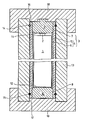
- the mold 1 is shown with the highly radioactive content, which can consist of glazed fission products from the reprocessing of spent fuel elements from nuclear reactors or from spent fuel elements themselves.
- the mold 1 has the known mushroom head 2 on its upper side for gripping. It is introduced into the actual longitudinal cylindrical storage container 3, the tubular wall 4 of which is composed of the two layers or tubes 5 and 6.
- the outer tube 5 is relatively thin-walled compared to the cover and bottom plugs 9, 10, ie with little shielding effect against above the radiation from the mold 1.
- the plugs 9 and 10 consist of normal structural steel, the corrosion rates of which are known under final storage conditions and the corrosion behavior of which can therefore be calculated.
- the inner tube 6 is now inserted tightly, e.g. shrunk in or connected by means of narrow gap welding.
- the inner tube 6 sits non-positively between the stopper and thus forms a continuous, wall 4 reinforcing support connection between the cover stopper 9 and the bottom stopper 10. Since the inner tube 6 is made of high-strength material, preferably tool steel, the axial load-bearing capacity of the repository container 3 is despite low wall thickness and calculable corrosion rate of the relatively soft material for the outer tube 5 increased considerably. This also increases the number of repository containers 3 that can be stacked in a borehole for strength reasons.
- a particularly favorable transport packaging for the final storage container 3 is formed by the thick-walled transport tube 13, which has a shielding effect and in which the container 3 is inserted.
- the container 3 is locked in the transport tube 13 by means of the securing bolts 14 and 15, which can be inserted radially or tangentially and can be released again for unloading.
- the end openings 16 and 17 of the tube 13 are closed by means of the end pieces 18 and 19, which in turn act as shock absorbers in the case of a container and which can also have an additional shielding effect.
- the end pieces 18 and 19 can have a larger outer diameter than the transport tube 13.
Landscapes
- Physics & Mathematics (AREA)
- Engineering & Computer Science (AREA)
- General Engineering & Computer Science (AREA)
- High Energy & Nuclear Physics (AREA)
- Processing Of Solid Wastes (AREA)
- Packages (AREA)
- Packaging Of Annular Or Rod-Shaped Articles, Wearing Apparel, Cassettes, Or The Like (AREA)
Description
Die vorliegende Erfindung betrifft einen Endlagerbehälter nach dem Oberbegriff des Patentanspruches 1.The present invention relates to a repository according to the preamble of
Die Erfindung befaßt sich allgemein mit der Bereitstellung eines Endlagergebindes für eine Einlagerung in eine geologische Formation, insbesondere in tiefen Bohrungen im Steinsalz. Es sollen dabei insbesondere Kokillen, die mit hochradioaktiven Abfällen gefüllt sind eingelagert werden. Folgende Probleme sind dabei zu lösen:The invention is generally concerned with the provision of a repository for storage in a geological formation, especially in deep holes in rock salt. In particular, molds that are filled with highly radioactive waste should be stored. The following problems have to be solved:
Gewährleistung einer mechanischen Stabilität gegen Gebirgsdruckbelastung um ca. 400 bar.Ensuring mechanical stability against rock pressure loads of approx. 400 bar.
Kalkulierbarer Korrosionsschutz, d.h. ein sichergestellter Flächenabtrag für einige 102 Jahre.Calculable corrosion protection, ie a guaranteed area erosion for some 10 2 years.
In vorhandene und bewährte Einrichtungen mit bekannten Greifkonturen und bekannte Glaskokillenlager soll das Endlagergebinde integrierbar sein.The repository package should be able to be integrated into existing and proven devices with known gripping contours and known glass mold bearings.
Hochradioaktiver, inbesondere verglaster Abfall wurde bisher noch nicht eingelagert. Die bisher bekannten Verpackungen, in die hochradioaktiver, verglaster Abfall eingefüllt ist, erfüllten keine Barrierefunktionen mit Langzeitisolierung im Endlager.Highly radioactive, especially glazed waste has not yet been stored. The previously known packaging, in which highly radioactive, glazed waste is filled, did not fulfill any barrier functions with long-term insulation in the repository.
Aus der EP-A 0 057 867 ist ein Lagerbehälter für die Langzeitlagerung bestrahlter Brennelemente mit einer Wandung aus mehreren Schichten bekannt, dessen Einzelschichten aus verschiedenartigen Werkstoffen bestehen, die von außen nach innen immer edler in bezug auf ihre Stellung in der elektrochemischen Spannungsreihe werden. Der Behälter ist jedoch hinsichtlich seiner Längsstabilität im Verhältnis zur Korrosionsfestigkeit nicht optimiert, so daß in einer Endlagerbohrung, in welcher die u.U. überschweren Behälter auf- bzw. übereinandergestapelt sind, ein Behälterversagen nicht ausgeschlossen werden kann.From EP-A 0 057 867 a storage container for the long-term storage of irradiated fuel elements with a wall of several layers is known, the individual layers of which consist of different types of materials that become more and more noble from the outside inwards with regard to their position in the electrochemical voltage series. However, the container is not optimized in terms of its longitudinal stability in relation to the corrosion resistance, so that in a repository bore in which the possibly. heavy containers are stacked or stacked, a container failure can not be excluded.
Bekannte Konzepte mit kalkulierbarem Korrosionsschutz (Flächenkorrosion von unlegiertem Stahl) haben folgende Nachteile:Known concepts with calculable corrosion protection (surface corrosion of unalloyed steel) have the following disadvantages:
Die Verwendung von unlegiertem Stahl für die Gesamtkonzeption des Behälters führt durch die erforderliche Materialwandstärke zu einer überproportionalen Gewichtszunahme des Endlagergebindes.The use of unalloyed steel for the overall design of the container leads to a disproportionate increase in the weight of the final storage container due to the required material wall thickness.
Die Abseiltechnik von sehr schweren Gebinden in tiefe Einlagerungsbohrlöcher von 300 bis 600 m Tiefe überschreitet oder stößt zumindest an die Grenze der technischen Realisierbarkeit. Sicherheitsstandard hierzu sind die technischen Anforderungen an Schacht- und Schrägförderanlagen.The abseiling technology of very heavy containers in deep storage boreholes from 300 to 600 m depth exceeds or at least reaches the limit of technical feasibility. The safety standard for this are the technical requirements for shaft and inclined conveyor systems.
Vorhandene Handhabungseinrichtungen für das Kokillenhandling und bewährte Zwischenlagereinrichtungen bei bekannten Glaskokillenlagern sind für überschwere Endlagergebinde nicht geeignet.Existing handling devices for mold handling and tried-and-tested interim storage devices in known glass mold bearings are not suitable for heavy repository containers.
Die optimale Ausnutzung einer schmalen, aber tiefen Endlagerformation, insbesondere aus Steinsalz, ist nur durch eine Einlagerung in tiefe Bohrungen zu gewährleisten. Überschwere Gebinde sind jedoch aus den oben bereits ausgeführten Gründen sowie aus Festigkeitsgründen hierzu nicht geeignet.The optimal use of a narrow but deep repository formation, especially of rock salt, can only be guaranteed by storing it in deep holes. However, heavier containers are not suitable for the reasons already mentioned above and for reasons of strength.
Ausgehend davon ist es nun Aufgabe der vorliegenden Erfindung, einen Endlagerbehälter für den Langzeiteinschluß von hochradioaktiven Materialien in geologischen Formationen, z.B. in tiefen Bohrungen von Salzstöcken zu schaffen, der beim Aufeinanderstapeln in einem Bohrloch mechanisch stabil bleibt, dem Gebirgsdruck widersteht, günstige thermische Eigenschaften sowie kalkulierbare Korrosionsraten aufweist und dessen Gewicht trotz sicherer Abschirmung der Streustrahlung beim Einbringen ins Bohrloch beschränkt bleiben kann. Gleichzeitig soll der Endlagerbehälter für seinen Transport den Aufbau einer sehr einfachen und kostengünstigen Transportverpackung ermöglichen und vom Gewicht her den Einlagerungsbedingungen entsprechen.Proceeding from this, it is an object of the present invention to provide a repository for the long-term containment of highly radioactive materials in geological formations, e.g. in deep boreholes of salt domes, which remains mechanically stable when stacked on top of one another in a borehole, withstands the rock pressure, has favorable thermal properties and calculable corrosion rates and the weight of which can remain limited despite reliable shielding of the scattered radiation when it is introduced into the borehole. At the same time, the repository container should enable the construction of a very simple and inexpensive transport packaging for its transport and should correspond to the storage conditions in terms of weight.
Zur Lösung dieser Aufgabe schlägt die vorliegende Erfindung nun die Merkmale vor, die im Kennzeichen des Anspruchs 1 sowie als vorteilhafte Weiterbildung in den Kennzeichen der Unteransprüche angegeben sind.To achieve this object, the present invention now proposes the features that are specified in the characterizing part of
Der besondere Vorteil des erfindungsgemäßen Endlagerbehälters besteht nun darin, daß die Gebirgsdruckbelastung durch den Einsatz einer Verbundkonstruktion mit hochfestem Innenrohr von dem Endlagergebinde aufgenommen werden kann, wobei der notwendige Korrosionsschutz durch das Aufschrumpfen eines unlegierten Stahles auf das hochfeste Innenrohr gewährleistet bleibt. Die Erfindung ermöglicht somit die Herstellung eines Kostengünstigen Endlagergebindes aus einfachen Massenwerkstoffen und Halbzeugen mit minimaler mechanischer Nachbearbeitung. Das geringe Gewicht des Endlagergebindes ermöglicht eine sichere Endlagerung in tiefen geologischen Formationen in Bohrungen. Die optimale Ausnutzung einer tiefen Steinsalzformation wird dadurch gewährleistet. Schnittstellenprobleme zu vorhandenen oder geplanten Einrichtungen wie Greiferkonturen oder die Handhabung und Einlagerung in bekannte Glaskokillenlager werden durch die erfindungsgemäße Gestaltung vermieden.The particular advantage of the repository container according to the invention is that the rock pressure load can be absorbed by the repository container by using a composite construction with a high-strength inner tube, the necessary corrosion protection being guaranteed by the shrinking of an unalloyed steel onto the high-strength inner tube. The invention thus enables the production of an inexpensive final storage container from simple bulk materials and semi-finished products with minimal mechanical post-processing. The low weight of the repository package enables safe disposal in deep geological formations in boreholes. This ensures optimal utilization of a deep rock salt formation. Interface problems with existing or planned facilities such as gripper contours or the handling and storage in known glass mold stores are avoided by the design according to the invention.
Die selbstabschirmende Wirkung des Deckel-und Bodenstopfens ermöglicht bei geringer Gewichtszunahme des Endlagergebindes den Aufbau eines sehr einfachen und kostengünstigen Typ B-Transportverpackung. Der verdickte Deckelstopfen vermindert sicher eine Dosisbelastung des Bedienungspersonals durch Streustrahlung bei der Abseilung des Endlagerungsgebindes in eine Einlagerungsbohrung. Zusatzabschirmungen können dadurch weitgehendst entfallen.The self-shielding effect of the lid and bottom plug enables the construction of a very simple and inexpensive type B transport packaging with a slight increase in the weight of the final storage container. The thickened cover stopper safely reduces the dose burden on the operating personnel due to scattered radiation when the final storage container is abseiled into an emptying hole. Additional shielding can thus be largely eliminated.
Weitere Einzelheiten der vorliegenden Erfindung sind im folgenden anhand der Figur näher erläutert, wobei die Figur schematisch einen Querschnitt durch die Behälteranordnung zeigt.Further details of the present invention are explained in more detail below with reference to the figure, the figure schematically showing a cross section through the container arrangement.
In der Figur ist die Kokille 1 mit dem hochradioaktiven Inhalt dargestellt, der aus verglasten Spaltprodukten aus der Wiederaufarbeitung abgebrannter Brennelemente von Kernreaktoren oder aus abgebrannten Brennelementen selbst bestehen kann. Die Kokille 1 weist an ihrer Oberseite zum Greifen den bekannten Pilzkopf 2 auf. Sie ist in den eigentlichen längszylindrischen Lagerbehälter 3 eingebracht, dessen rohrförmige Wandung 4 aus den beiden Schichten bzw. Rohren 5 und 6 zusammengesetzt ist. Das Außenrohr 5 ist gegenüber den Deckel- und Bodenstopfen 9, 10 relativ dünnwandig ausgebildet, d.h. mit wenig Abschirmwirkung gegenüber der Strahlung aus der Kokille 1. Es ist an seinen oberen und unteren Enden bzw. Öffnungen 7 und 8 mittels der dicht eingesetzten, z.B. eingeschweißten oder eingeschrumpften Deckel- und Bodenstopfen 9 und 10 verschlossen, deren Dicke ein mehrfaches der Wandstärke des Außenrohres 5 beträgt und die - in axialer Richtung gesehen - die Strahlung aus der Kokille in Längsrichtung des Endlagerbehälters 3 abschirmen. Die Stopfen 9 und 10 bestehen aus normalem Baustahl, dessen Korrosionsraten unter Endlagerbedingungen bekannt sind und dessen Korrosionsverhalten daher kalkulierbar ist.In the figure, the
In das Außenrohr 5 ist nun zwischen den Stirnseiten 11 und 12 der Stopfen 9 und 10 das Innenrohr 6 dicht eingesetzt, z.B. eingeschrumpft bzw. mittels Engspaltschweißung verbunden. Das Innenrohr 6 sitzt kraftschlüssig zwischen den Stopfen und bildet damit eine durchgehende, die Wandung 4 verstärkende Stützverbindung zwischen dem Deckelstopfen 9 und dem Bodenstopfen 10. Da das Innenrohr 6 aus hochfestem Werkstoff, vorzugsweise aus Werkzeugstahl besteht, wird somit die axiale Tragfähigkeit des Endlagerbehälters 3 trotz geringer Wandstärke und kalkulierbarer Korrosionsrate des relativ weichen Materiales für das Außenrohr 5 erheblich erhöht. Damit erhöht sich auch die Zahl der aus Festigkeitsgründen in einem Bohrloch aufeinander stapelbaren Endlagerbehälter 3.In the outer tube 5 between the end faces 11 and 12 of the plugs 9 and 10, the inner tube 6 is now inserted tightly, e.g. shrunk in or connected by means of narrow gap welding. The inner tube 6 sits non-positively between the stopper and thus forms a continuous, wall 4 reinforcing support connection between the cover stopper 9 and the bottom stopper 10. Since the inner tube 6 is made of high-strength material, preferably tool steel, the axial load-bearing capacity of the
Eine besonders günstige Transportverpackung für den Endlagerbehälter 3 bildet das dickwandige Transportrohr 13, das Abschirmwirkung besitzt und in welches der Behälter 3 eingesetzt wird. Die Verriegelung des Behälters 3 im Transportrohr 13 erfolgt mittels der Sicherungsbolzen 14 und 15, die radial oder tangential einschiebbar sind und zur Entladung wieder gelöst werden können. Die stirnseitigen Öffnungen 16 und 17 des Rohres 13 sind mittels der Endstücke 18 und 19 verschlossen, die ihrerseits als Stoßdämpfer beim Behälterfall wirken und die ebenfalls zusätzliche Abschirmwirkung besitzen können. Die Endstücke 18 und 19 können dabei größeren Außendurchmesser als das Transportrohr 13 aufweisen.A particularly favorable transport packaging for the
Claims (2)
Applications Claiming Priority (2)
| Application Number | Priority Date | Filing Date | Title |
|---|---|---|---|
| DE19863610862 DE3610862A1 (en) | 1986-04-01 | 1986-04-01 | LENGTH CYLINDRICAL CONTAINER FOR THE FINAL STORAGE OF ONE OR MORE CHILLERS FILLED WITH HIGH RADIOACTIVE WASTE |
| DE3610862 | 1986-04-01 |
Publications (2)
| Publication Number | Publication Date |
|---|---|
| EP0244599A1 EP0244599A1 (en) | 1987-11-11 |
| EP0244599B1 true EP0244599B1 (en) | 1990-06-13 |
Family
ID=6297653
Family Applications (1)
| Application Number | Title | Priority Date | Filing Date |
|---|---|---|---|
| EP19870103768 Expired - Lifetime EP0244599B1 (en) | 1986-04-01 | 1987-03-16 | Cylindrical container for the final storage of one or more radio-active waste-filled flasks |
Country Status (2)
| Country | Link |
|---|---|
| EP (1) | EP0244599B1 (en) |
| DE (1) | DE3610862A1 (en) |
Families Citing this family (6)
| Publication number | Priority date | Publication date | Assignee | Title |
|---|---|---|---|---|
| DE19538008B4 (en) * | 1995-10-12 | 2008-04-17 | Areva Np Gmbh | Storage container for receiving radioactive material and methods for storing spent fuel |
| DE29800282U1 (en) | 1998-01-13 | 1998-06-10 | Siemens AG, 80333 München | Nuclear reactor fuel element ready for dispatch |
| FR2774800B1 (en) * | 1998-02-10 | 2000-05-05 | Framatome Sa | TRANSPORT CONTAINER FOR NUCLEAR FUEL ASSEMBLIES |
| DE29909347U1 (en) | 1999-05-28 | 1999-11-11 | Reinhardt, Horst, Dipl.-Ing., 63110 Rodgau | Metallic contamination protection for nuclear transport containers |
| DE102007016141A1 (en) * | 2007-04-02 | 2008-10-09 | Evonik Energy Services Gmbh | Container system for receiving radioactive waste |
| DE102010017201A1 (en) | 2010-03-07 | 2011-09-08 | Dieter Pfaltz | Containers for the disposal of solid or liquid special waste materials made of laminated glass or bulletproof glass |
Family Cites Families (7)
| Publication number | Priority date | Publication date | Assignee | Title |
|---|---|---|---|---|
| DE2952168C2 (en) * | 1979-12-22 | 1982-09-02 | Transnuklear Gmbh, 6450 Hanau | Transport and / or storage containers for radioactive substances |
| DE3037328C2 (en) * | 1980-10-02 | 1982-12-23 | Transnuklear Gmbh, 6450 Hanau | Shock absorbers for containers for the transport and / or storage of radioactive material |
| DE3046082C2 (en) * | 1980-12-06 | 1987-02-12 | Kernforschungszentrum Karlsruhe Gmbh, 7500 Karlsruhe | Storage and transport container arrangement for one or more moulds filled with radioactive waste encased in glass |
| DE3103526C2 (en) * | 1981-02-03 | 1985-11-14 | Deutsche Gesellschaft für Wiederaufarbeitung von Kernbrennstoffen mbH, 3000 Hannover | Multi-layer transport and storage container for radioactive waste |
| EP0057867A1 (en) * | 1981-02-03 | 1982-08-18 | Nukem GmbH | Multi-layered container for the safe long-term storage of radioactive material |
| DE3214880A1 (en) * | 1982-04-22 | 1983-10-27 | Deutsche Gesellschaft für Wiederaufarbeitung von Kernbrennstoffen mbH, 3000 Hannover | CONTAINER TO RECEIVE RADIOACTIVE SUBSTANCES |
| DE3404666A1 (en) * | 1984-02-10 | 1985-08-14 | GNS Gesellschaft für Nuklear-Service mbH, 4300 Essen | Shielded shipping and shielded storage cask for spent fuel elements |
-
1986
- 1986-04-01 DE DE19863610862 patent/DE3610862A1/en active Granted
-
1987
- 1987-03-16 EP EP19870103768 patent/EP0244599B1/en not_active Expired - Lifetime
Also Published As
| Publication number | Publication date |
|---|---|
| EP0244599A1 (en) | 1987-11-11 |
| DE3610862A1 (en) | 1987-10-08 |
| DE3610862C2 (en) | 1993-02-11 |
Similar Documents
| Publication | Publication Date | Title |
|---|---|---|
| DE69218258T2 (en) | PRESSURE VESSEL | |
| DE3028424C2 (en) | Shock absorbers | |
| DE3437534C2 (en) | Cylindrical container for use as a pressure-tight explosion chamber | |
| DE2839759A1 (en) | CLOSURE OF BEARING HOLES FOR FINAL STORAGE OF RADIOACTIVE WASTE AND METHOD FOR ATTACHING THE CLOSURE | |
| DE69908002T2 (en) | Radiation protection device for containers for the transport of radioactive substances and method for installing such a radiation protection device | |
| DE2500927A1 (en) | DEVICE FOR HANDLING RADIOACTIVE NUCLEAR FUEL ELEMENTS DURING TRANSPORT OPERATIONS | |
| EP0244599B1 (en) | Cylindrical container for the final storage of one or more radio-active waste-filled flasks | |
| DE69414137T2 (en) | IN essence, a bundle of adjacent tube-containing storage frames for nuclear fuel bundles | |
| DE2418518A1 (en) | STORAGE DEVICE FOR RADIOACTIVE WASTE | |
| DE3322770A1 (en) | DEVICE FOR HANDLING AND PROTECTING STORAGE CONTAINERS FOR RADIOACTIVE SUBSTANCES | |
| DE3132704A1 (en) | CONTAINER FOR LONG-TERM STORAGE OF RADIOACTIVE WASTE | |
| EP0175174B1 (en) | Control rod for nuclear reactors | |
| DE3125211A1 (en) | STORAGE CONTAINER AND METHOD FOR THE PRODUCTION THEREOF | |
| EP0057867A1 (en) | Multi-layered container for the safe long-term storage of radioactive material | |
| DE2716463C2 (en) | Disposable shielded container for the transport and final storage of radioactive waste in the sea | |
| EP0043096B1 (en) | Device for the storage of radioactive materials | |
| DE2919797C2 (en) | Storage facility for the storage of spent fuel | |
| DE3216855C2 (en) | Containers for storing new fuel assemblies | |
| EP0102562B1 (en) | Storage container for solutions of fission products | |
| EP0044024B1 (en) | Container for transporting and/or storing radioactive materials | |
| DE2228026A1 (en) | Transport container | |
| DE3227512A1 (en) | Consumable shielding container for radioactive waste | |
| DE3237712C2 (en) | Process for the disposal of a hazardous material, in particular pulverized radioactive material | |
| DE3028040C2 (en) | Arrangement for the storage of radioactive waste liquids | |
| DE2554576A1 (en) | Reinforced and/or pre-stressed concrete cell structure - used in nuclear installations and incorporates plastics foam filling between double wall |
Legal Events
| Date | Code | Title | Description |
|---|---|---|---|
| PUAI | Public reference made under article 153(3) epc to a published international application that has entered the european phase |
Free format text: ORIGINAL CODE: 0009012 |
|
| AK | Designated contracting states |
Kind code of ref document: A1 Designated state(s): BE CH FR GB LI NL SE |
|
| 17P | Request for examination filed |
Effective date: 19871111 |
|
| 17Q | First examination report despatched |
Effective date: 19881014 |
|
| GRAA | (expected) grant |
Free format text: ORIGINAL CODE: 0009210 |
|
| AK | Designated contracting states |
Kind code of ref document: B1 Designated state(s): BE CH FR GB LI NL SE |
|
| ET | Fr: translation filed | ||
| GBT | Gb: translation of ep patent filed (gb section 77(6)(a)/1977) | ||
| PLBE | No opposition filed within time limit |
Free format text: ORIGINAL CODE: 0009261 |
|
| STAA | Information on the status of an ep patent application or granted ep patent |
Free format text: STATUS: NO OPPOSITION FILED WITHIN TIME LIMIT |
|
| 26N | No opposition filed | ||
| PGFP | Annual fee paid to national office [announced via postgrant information from national office to epo] |
Ref country code: GB Payment date: 19920123 Year of fee payment: 6 |
|
| PGFP | Annual fee paid to national office [announced via postgrant information from national office to epo] |
Ref country code: CH Payment date: 19920129 Year of fee payment: 6 |
|
| PGFP | Annual fee paid to national office [announced via postgrant information from national office to epo] |
Ref country code: SE Payment date: 19920316 Year of fee payment: 6 |
|
| PGFP | Annual fee paid to national office [announced via postgrant information from national office to epo] |
Ref country code: FR Payment date: 19920330 Year of fee payment: 6 |
|
| PGFP | Annual fee paid to national office [announced via postgrant information from national office to epo] |
Ref country code: NL Payment date: 19920331 Year of fee payment: 6 |
|
| PG25 | Lapsed in a contracting state [announced via postgrant information from national office to epo] |
Ref country code: GB Effective date: 19930316 |
|
| PG25 | Lapsed in a contracting state [announced via postgrant information from national office to epo] |
Ref country code: SE Effective date: 19930317 |
|
| PG25 | Lapsed in a contracting state [announced via postgrant information from national office to epo] |
Ref country code: LI Effective date: 19930331 Ref country code: CH Effective date: 19930331 |
|
| PGFP | Annual fee paid to national office [announced via postgrant information from national office to epo] |
Ref country code: BE Payment date: 19930511 Year of fee payment: 7 |
|
| PG25 | Lapsed in a contracting state [announced via postgrant information from national office to epo] |
Ref country code: NL Effective date: 19931001 |
|
| GBPC | Gb: european patent ceased through non-payment of renewal fee |
Effective date: 19930316 |
|
| NLV4 | Nl: lapsed or anulled due to non-payment of the annual fee | ||
| PG25 | Lapsed in a contracting state [announced via postgrant information from national office to epo] |
Ref country code: FR Effective date: 19931130 |
|
| REG | Reference to a national code |
Ref country code: CH Ref legal event code: PL |
|
| REG | Reference to a national code |
Ref country code: FR Ref legal event code: ST |
|
| PG25 | Lapsed in a contracting state [announced via postgrant information from national office to epo] |
Ref country code: BE Effective date: 19940331 |
|
| BERE | Be: lapsed |
Owner name: KERNFORSCHUNGSZENTRUM KARLSRUHE G.M.B.H. Effective date: 19940331 |
|
| EUG | Se: european patent has lapsed |
Ref document number: 87103768.5 Effective date: 19931008 |