EP0244580B1 - Apparatus for inductive heating - Google Patents
Apparatus for inductive heating Download PDFInfo
- Publication number
- EP0244580B1 EP0244580B1 EP87102698A EP87102698A EP0244580B1 EP 0244580 B1 EP0244580 B1 EP 0244580B1 EP 87102698 A EP87102698 A EP 87102698A EP 87102698 A EP87102698 A EP 87102698A EP 0244580 B1 EP0244580 B1 EP 0244580B1
- Authority
- EP
- European Patent Office
- Prior art keywords
- coil
- flat
- product
- edges
- bent
- Prior art date
- Legal status (The legal status is an assumption and is not a legal conclusion. Google has not performed a legal analysis and makes no representation as to the accuracy of the status listed.)
- Expired - Lifetime
Links
- 238000010438 heat treatment Methods 0.000 title claims abstract description 7
- 230000001939 inductive effect Effects 0.000 title abstract description 6
- 230000006698 induction Effects 0.000 claims 3
- 238000009749 continuous casting Methods 0.000 abstract 1
- 238000005098 hot rolling Methods 0.000 abstract 1
- 239000002184 metal Substances 0.000 abstract 1
- 238000011161 development Methods 0.000 description 1
- 230000018109 developmental process Effects 0.000 description 1
- 238000009826 distribution Methods 0.000 description 1
- 238000004519 manufacturing process Methods 0.000 description 1
- 238000000034 method Methods 0.000 description 1
- 238000005096 rolling process Methods 0.000 description 1
Images

Classifications
-
- C—CHEMISTRY; METALLURGY
- C21—METALLURGY OF IRON
- C21D—MODIFYING THE PHYSICAL STRUCTURE OF FERROUS METALS; GENERAL DEVICES FOR HEAT TREATMENT OF FERROUS OR NON-FERROUS METALS OR ALLOYS; MAKING METAL MALLEABLE, e.g. BY DECARBURISATION OR TEMPERING
- C21D9/00—Heat treatment, e.g. annealing, hardening, quenching or tempering, adapted for particular articles; Furnaces therefor
- C21D9/52—Heat treatment, e.g. annealing, hardening, quenching or tempering, adapted for particular articles; Furnaces therefor for wires; for strips ; for rods of unlimited length
- C21D9/54—Furnaces for treating strips or wire
- C21D9/56—Continuous furnaces for strip or wire
- C21D9/60—Continuous furnaces for strip or wire with induction heating
-
- Y—GENERAL TAGGING OF NEW TECHNOLOGICAL DEVELOPMENTS; GENERAL TAGGING OF CROSS-SECTIONAL TECHNOLOGIES SPANNING OVER SEVERAL SECTIONS OF THE IPC; TECHNICAL SUBJECTS COVERED BY FORMER USPC CROSS-REFERENCE ART COLLECTIONS [XRACs] AND DIGESTS
- Y02—TECHNOLOGIES OR APPLICATIONS FOR MITIGATION OR ADAPTATION AGAINST CLIMATE CHANGE
- Y02P—CLIMATE CHANGE MITIGATION TECHNOLOGIES IN THE PRODUCTION OR PROCESSING OF GOODS
- Y02P10/00—Technologies related to metal processing
- Y02P10/25—Process efficiency
Definitions
- the invention relates to an assembly for heating the edge portions of a flat product according to the precharacterising part of Claim 1.
- Such an assembly is known from the EP-A-0 183 209.
- the inductive heaters are arranged to surround the flat product, such as a billet on its way to a rolling mill, on three sides and are suitably arranged to be supplied with a single-phase current of mains frequency or high frequency in the range of 1000-3000 Hz.
- the invention aims at an assembly for heating the edge portions of a flat product of the above-mentioned kind which allows to keep the flat product across its entire cross-section at approximately the same temperature.
- the assembly according to the invention is intended to reduce the temperature differences revealed in Figure 1. After transport of a product through the assembly, the energy supplied to the billet will be typically distributed as delta T.
- Figure 2 shows a triangular coil 1 designed to surround a side edge of a flat product on three sides.
- the coil 1 is supplied via its terminals 2 with a current of single phase mains frequency or high frequency in the range 1000-3000 Hz.
- Figure 3 shows one side edge of a flat billet, such as a slab or the like, which is surrounded in the afore-said manner by the coil 1.
- the turns of the coil 1 are wound triangularly so that the outermost parts of the side edge 3 pass more turns of the coil than the sections located more distant from the edge (see the above-mentioned EP-A-85114886).
- One or more vertical flat coils 4 are arranged in series with or parallel to the coil 1, parallel to the side edge, and this or these coil(s) can be arranged, together with the coils 1, within the same roll gap.
- the supply sources for the various coils 1,4 may be separate, thus enabling individual variation of the field strength and/or frequency.
Landscapes
- Chemical & Material Sciences (AREA)
- Engineering & Computer Science (AREA)
- Physics & Mathematics (AREA)
- Thermal Sciences (AREA)
- Crystallography & Structural Chemistry (AREA)
- Mechanical Engineering (AREA)
- Materials Engineering (AREA)
- Metallurgy (AREA)
- Organic Chemistry (AREA)
- General Induction Heating (AREA)
- Control Of High-Frequency Heating Circuits (AREA)
Abstract
Description
- The invention relates to an assembly for heating the edge portions of a flat product according to the precharacterising part of
Claim 1. Such an assembly is known from the EP-A-0 183 209. - A similar assembly is described in the EP-A-85 11 4886, the heater(s) constituting one or more bent, flat spiral coil(s), arranged so that the outermost parts of the edges will pass a greater portion of the coil than parts located further from the edges, the outer edge thus being heated more than the inner parts of the product. This results in keeping the outer edges at a temperature corresponding approximately to that of the rest of the product, for example a billet, sheet, or strip.
- The inductive heaters are arranged to surround the flat product, such as a billet on its way to a rolling mill, on three sides and are suitably arranged to be supplied with a single-phase current of mains frequency or high frequency in the range of 1000-3000 Hz.
- In processes where flat products are to be kept hot along the production line, the products cool more quickly at the edges than in their remaining sections. Often the heating assembly described above is sufficient. However, as is also apparent from a study of temperatures from calculated temperature distribution for slabs or other flat products, sometimes a more complete compensation for the loss of heat at the edges is required.
- The invention aims at an assembly for heating the edge portions of a flat product of the above-mentioned kind which allows to keep the flat product across its entire cross-section at approximately the same temperature.
- To achieve this aim the invention suggests an assembly according to the introductory part of
Claim 1, which is characterized by the features of the characterizing part ofClaim 1. - Further developments of the invention are characterized by the features of the additional claims.
- In a assembly according to the invention a substantially complete temperature and heat-loss compensation will be obtained along the edges of the flat billets to be further worked.
- The invention will now be described in greater detail with reference to the accompanying drawings showing - by way of example - in
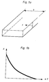
- Figure 1
- the typical temperature conditions in a flat product prior to the application of an assembly according to the invention,
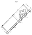
- Figure 2
- a heater in an assembly according to the invention with combined coils,
- Figure 3
- a side view of the inductive heater in Figure 2 with a side edge of the product,
- The assembly according to the invention is intended to reduce the temperature differences revealed in Figure 1. After transport of a product through the assembly, the energy supplied to the billet will be typically distributed as delta T.
- Figure 2 shows a
triangular coil 1 designed to surround a side edge of a flat product on three sides. Thecoil 1 is supplied via itsterminals 2 with a current of single phase mains frequency or high frequency in the range 1000-3000 Hz. Figure 3 shows one side edge of a flat billet, such as a slab or the like, which is surrounded in the afore-said manner by thecoil 1. The turns of thecoil 1 are wound triangularly so that the outermost parts of theside edge 3 pass more turns of the coil than the sections located more distant from the edge (see the above-mentioned EP-A-85114886). - One or more vertical
flat coils 4 are arranged in series with or parallel to thecoil 1, parallel to the side edge, and this or these coil(s) can be arranged, together with thecoils 1, within the same roll gap. - The combination of a
triangular coil 1 with a verticalflat coil 4 at theedge sides 5 enables the temperature of the edge and corners to be increased even further. - The combination according to Figure 2 is thus effected so that the triangular coil is placed in the gap between two consecutive rolls of a conveyor belt and that the
flat coil 4 is placed in the same gap. The space requirement for the inductive heater in longitudinal direction is thus limited. - The supply sources for the
various coils - The assembly according to the above can be varied in many ways within the scope of the following claims.
Figure 1 shows typical temperature conditions prior to edge heating. x is the distance from the outer edge of the product and b is the width of the product. Delta T is the difference between the mean temperature at various distances x from the edge and the mean temperature at the centre of the billet. x is smaller than b/2.
Claims (4)
- Assembly for heating a side edge portion of a travelling flat product, such as a billet, and comprising a first induction coil, in the form of a flat spiral coil (1) bent into a U-shaped form having horizontal sides which are triangular in shape, spaced apart and positioned to overlie the mutually opposite sides of said flat product, travelling between said horizontal sides of the said first induction coil, characterized in that the assembly also includes a second induction coil (4) which is flat in shape and positioned in a vertical plane parallel to the billet's side edge (5), the second coil (4) having a height less than the spacing between the horizontal sides of the first coil and that the second coil is positioned between the horizontal sides of the first coil (1) such as to cooperate with the first coil.
- Assembly according to claim 1, characterized in that the bent, flat spiral coil(s) (1) and the vertical flat coil(s) (4) are combined to form a coil unit located within the same roll-gap (7).
- Assembly according to claims 2 or 3, characterized in that the bent, flat spiral coil(s) (1) and the vertical flat coil(s) are supplied from different power sources, to permit individual variation of the field strength and/or the frequency, for instance.
- Assembly according to any of the preceding claims, characterized in that the bent, flat spiral coil(s) (1) are so shaped that the outermost part of the edges will pass a greater portion of the coil than portions located further from the edges, and that the coils surround the edges on three sides.
Priority Applications (1)
| Application Number | Priority Date | Filing Date | Title |
|---|---|---|---|
| AT87102698T ATE88312T1 (en) | 1986-03-03 | 1987-02-25 | INDUCTION HEATING DEVICE. |
Applications Claiming Priority (2)
| Application Number | Priority Date | Filing Date | Title |
|---|---|---|---|
| SE8600940A SE452085B (en) | 1986-03-03 | 1986-03-03 | DEVICE FOR HEATING THE SUBJECT, TAPE OR PLATE |
| SE8600940 | 1986-03-03 |
Publications (2)
| Publication Number | Publication Date |
|---|---|
| EP0244580A1 EP0244580A1 (en) | 1987-11-11 |
| EP0244580B1 true EP0244580B1 (en) | 1993-04-14 |
Family
ID=20363656
Family Applications (1)
| Application Number | Title | Priority Date | Filing Date |
|---|---|---|---|
| EP87102698A Expired - Lifetime EP0244580B1 (en) | 1986-03-03 | 1987-02-25 | Apparatus for inductive heating |
Country Status (7)
| Country | Link |
|---|---|
| US (1) | US4857687A (en) |
| EP (1) | EP0244580B1 (en) |
| JP (1) | JPH0797515B2 (en) |
| AT (1) | ATE88312T1 (en) |
| CA (1) | CA1276986C (en) |
| DE (1) | DE3785385T2 (en) |
| SE (1) | SE452085B (en) |
Families Citing this family (6)
| Publication number | Priority date | Publication date | Assignee | Title |
|---|---|---|---|---|
| US5032700A (en) * | 1987-06-09 | 1991-07-16 | Toyo Seikan Kaisha, Ltd. | Method of heating thermoplastic bottle of preform and method of controlling temperature of heating member utilized by the heating method |
| US5306365A (en) * | 1992-11-19 | 1994-04-26 | Aluminum Company Of America | Apparatus and method for tapered heating of metal billet |
| US5630958A (en) * | 1995-01-27 | 1997-05-20 | Stewart, Jr.; John B. | Side entry coil induction heater with flux concentrator |
| JPH105802A (en) * | 1996-06-28 | 1998-01-13 | Nkk Corp | Welding continuous rolling method and apparatus |
| ES2231549T3 (en) * | 2000-08-29 | 2005-05-16 | Otto Junker Gmbh | DEVICE FOR HEATING METAL BANDS BY INDUCTION. |
| DE102006052138A1 (en) * | 2006-05-16 | 2007-11-22 | Sms Demag Ag | Method and strand guiding device for guiding a cast strand |
Family Cites Families (12)
| Publication number | Priority date | Publication date | Assignee | Title |
|---|---|---|---|---|
| US2401899A (en) * | 1942-04-30 | 1946-06-11 | Rca Corp | Apparatus for treating metal |
| US2479341A (en) * | 1948-03-16 | 1949-08-16 | Gen Electric | Induction heating apparatus |
| US3562470A (en) * | 1969-06-24 | 1971-02-09 | Westinghouse Electric Corp | Induction heating apparatus |
| DE1963368B2 (en) * | 1969-12-18 | 1971-06-16 | Aeg Elotherm Gmbh | DEVICE FOR INDUCTIVE HEATING OF MAJORLY ROTATIONAL SYMMETRIC WORKPIECES, PRESENTLY FOR THE PURPOSE OF SURFACE HARDENING |
| US3731040A (en) * | 1971-09-24 | 1973-05-01 | Park Ohio Industries Inc | Billet heating coil |
| GB1371972A (en) * | 1971-12-07 | 1974-10-30 | Hasenclever Gmbh Maschf | Machine for upsetting the ends of bars and similar rod-shaped metallic workpieces |
| DE2734916C3 (en) * | 1977-08-03 | 1981-10-22 | Estel Hoesch Werke Ag, 4600 Dortmund | Inductor for heating raceway surfaces on roller bearing rings |
| US4458127A (en) * | 1981-05-26 | 1984-07-03 | Park-Ohio Industries, Inc. | Inductor for annealing work hardened portions of structural beams |
| US4458125A (en) * | 1981-08-10 | 1984-07-03 | Battelle Memorial Institute | Repair method and apparatus |
| JPS58189330A (en) * | 1982-04-30 | 1983-11-05 | Hitachi Ltd | Heat treatment of piping system and coil for heating |
| FR2558941B1 (en) * | 1984-01-26 | 1986-05-02 | Cem Comp Electro Mec | DEVICE FOR HEATING FLAT PRODUCTS IN A RUNWAY BY ELECTROMAGNETIC INDUCTION |
| SE8406062L (en) * | 1984-11-30 | 1986-05-12 | Asea Ab | INDUCTIVE EDGE HEATER |
-
1986
- 1986-03-03 SE SE8600940A patent/SE452085B/en not_active IP Right Cessation
-
1987
- 1987-02-25 DE DE87102698T patent/DE3785385T2/en not_active Expired - Fee Related
- 1987-02-25 AT AT87102698T patent/ATE88312T1/en not_active IP Right Cessation
- 1987-02-25 EP EP87102698A patent/EP0244580B1/en not_active Expired - Lifetime
- 1987-03-02 JP JP62047415A patent/JPH0797515B2/en not_active Expired - Lifetime
- 1987-03-02 CA CA000530883A patent/CA1276986C/en not_active Expired - Lifetime
-
1988
- 1988-10-12 US US07/257,142 patent/US4857687A/en not_active Expired - Fee Related
Also Published As
| Publication number | Publication date |
|---|---|
| US4857687A (en) | 1989-08-15 |
| DE3785385T2 (en) | 1993-10-28 |
| SE452085B (en) | 1987-11-09 |
| ATE88312T1 (en) | 1993-04-15 |
| JPH0797515B2 (en) | 1995-10-18 |
| DE3785385D1 (en) | 1993-05-19 |
| SE8600940D0 (en) | 1986-03-03 |
| JPS62211891A (en) | 1987-09-17 |
| SE8600940L (en) | 1987-09-04 |
| CA1276986C (en) | 1990-11-27 |
| EP0244580A1 (en) | 1987-11-11 |
Similar Documents
| Publication | Publication Date | Title |
|---|---|---|
| US4708325A (en) | Induction heating system for reheating the edges of a metallurgical product and variable air gap inductor associated therewith | |
| EP0429581B1 (en) | Induction furnace for heating and temperature homogenization in hot-rolling of thin steel strips | |
| EP0183209B1 (en) | Inductive heater for heating the edges of a longitudinally extending body with a flat cross-section | |
| KR100698502B1 (en) | Hot rolled steel sheet and hot rolled device | |
| EP1610591B1 (en) | Transverse type induction heating device | |
| CA2109397A1 (en) | Method of and apparatus for manufacturing hot rolled steel strips, in particular from strip-shaped continuously cast primary material | |
| EP0244580B1 (en) | Apparatus for inductive heating | |
| HU216981B (en) | Induction furnace | |
| US3562470A (en) | Induction heating apparatus | |
| US3705967A (en) | Induction heating method | |
| US4745252A (en) | Device for the homogenization of the temperature of passing metallic products | |
| US20070051152A1 (en) | Device for heating a metal strip, and apparatuses equipped with a device of this type, for producing hot-rolled metal strip | |
| EP0904861B1 (en) | Method of producing thin hot rolled steel sheet, and apparatus to carry out the method | |
| JP2002172401A (en) | Continuous casting hot rolling equipment and continuous casting hot rolling method | |
| US4321449A (en) | Apparatus for induction heating of metal products, particularly slabs and blooms | |
| US5245148A (en) | Apparatus for and method of heating thick metal slabs | |
| WO1995013149A1 (en) | Slab caster and inline strip and plate apparatus | |
| EP0208679B1 (en) | Method for the reduction of local temperature irregularity in steel slabs at rolling | |
| JPH04339502A (en) | Manufacture of medium and small bar steels | |
| JP2529932B2 (en) | Hot coil manufacturing equipment | |
| KR100250673B1 (en) | Production method and apparatus for hot rolled steel sheet | |
| JP2004034069A (en) | Hot rolling method and apparatus for steel sheet | |
| JPS5926370B2 (en) | Method of heating steel billet for hot rolling | |
| GB2263875A (en) | A process for heating thin metallic sheet and a furnace for carrying out the process | |
| JPH09170023A (en) | How to heat the material to be heated |
Legal Events
| Date | Code | Title | Description |
|---|---|---|---|
| PUAI | Public reference made under article 153(3) epc to a published international application that has entered the european phase |
Free format text: ORIGINAL CODE: 0009012 |
|
| AK | Designated contracting states |
Kind code of ref document: A1 Designated state(s): AT DE FR GB IT |
|
| 17P | Request for examination filed |
Effective date: 19880421 |
|
| 17Q | First examination report despatched |
Effective date: 19900802 |
|
| GRAA | (expected) grant |
Free format text: ORIGINAL CODE: 0009210 |
|
| AK | Designated contracting states |
Kind code of ref document: B1 Designated state(s): AT DE FR GB IT |
|
| PG25 | Lapsed in a contracting state [announced via postgrant information from national office to epo] |
Ref country code: IT Free format text: LAPSE BECAUSE OF FAILURE TO SUBMIT A TRANSLATION OF THE DESCRIPTION OR TO PAY THE FEE WITHIN THE PRE;WARNING: LAPSES OF ITALIAN PATENTS WITH EFFECTIVE DATE BEFORE 2007 MAY HAVE OCCURRED AT ANY TIME BEFORE 2007. THE CORRECT EFFECTIVE DATE MAY BE DIFFERENT FROM THE ONE RECORDED.SCRIBED TIME-LIMIT Effective date: 19930414 Ref country code: AT Effective date: 19930414 |
|
| REF | Corresponds to: |
Ref document number: 88312 Country of ref document: AT Date of ref document: 19930415 Kind code of ref document: T |
|
| REF | Corresponds to: |
Ref document number: 3785385 Country of ref document: DE Date of ref document: 19930519 |
|
| ET | Fr: translation filed | ||
| PGFP | Annual fee paid to national office [announced via postgrant information from national office to epo] |
Ref country code: FR Payment date: 19940210 Year of fee payment: 8 |
|
| PGFP | Annual fee paid to national office [announced via postgrant information from national office to epo] |
Ref country code: GB Payment date: 19940215 Year of fee payment: 8 |
|
| PLBE | No opposition filed within time limit |
Free format text: ORIGINAL CODE: 0009261 |
|
| STAA | Information on the status of an ep patent application or granted ep patent |
Free format text: STATUS: NO OPPOSITION FILED WITHIN TIME LIMIT |
|
| PGFP | Annual fee paid to national office [announced via postgrant information from national office to epo] |
Ref country code: DE Payment date: 19940224 Year of fee payment: 8 |
|
| 26N | No opposition filed | ||
| PG25 | Lapsed in a contracting state [announced via postgrant information from national office to epo] |
Ref country code: GB Effective date: 19950225 |
|
| GBPC | Gb: european patent ceased through non-payment of renewal fee |
Effective date: 19950225 |
|
| PG25 | Lapsed in a contracting state [announced via postgrant information from national office to epo] |
Ref country code: FR Effective date: 19951031 |
|
| PG25 | Lapsed in a contracting state [announced via postgrant information from national office to epo] |
Ref country code: DE Effective date: 19951101 |
|
| REG | Reference to a national code |
Ref country code: FR Ref legal event code: ST |