EP0244551B1 - Integrated metallurgical plant - Google Patents
Integrated metallurgical plant Download PDFInfo
- Publication number
- EP0244551B1 EP0244551B1 EP19860890130 EP86890130A EP0244551B1 EP 0244551 B1 EP0244551 B1 EP 0244551B1 EP 19860890130 EP19860890130 EP 19860890130 EP 86890130 A EP86890130 A EP 86890130A EP 0244551 B1 EP0244551 B1 EP 0244551B1
- Authority
- EP
- European Patent Office
- Prior art keywords
- plant
- gas
- converters
- reformer
- coke oven
- Prior art date
- Legal status (The legal status is an assumption and is not a legal conclusion. Google has not performed a legal analysis and makes no representation as to the accuracy of the status listed.)
- Expired - Lifetime
Links
Images
Classifications
-
- C—CHEMISTRY; METALLURGY
- C21—METALLURGY OF IRON
- C21B—MANUFACTURE OF IRON OR STEEL
- C21B13/00—Making spongy iron or liquid steel, by direct processes
-
- Y—GENERAL TAGGING OF NEW TECHNOLOGICAL DEVELOPMENTS; GENERAL TAGGING OF CROSS-SECTIONAL TECHNOLOGIES SPANNING OVER SEVERAL SECTIONS OF THE IPC; TECHNICAL SUBJECTS COVERED BY FORMER USPC CROSS-REFERENCE ART COLLECTIONS [XRACs] AND DIGESTS
- Y02—TECHNOLOGIES OR APPLICATIONS FOR MITIGATION OR ADAPTATION AGAINST CLIMATE CHANGE
- Y02P—CLIMATE CHANGE MITIGATION TECHNOLOGIES IN THE PRODUCTION OR PROCESSING OF GOODS
- Y02P10/00—Technologies related to metal processing
- Y02P10/10—Reduction of greenhouse gas [GHG] emissions
- Y02P10/122—Reduction of greenhouse gas [GHG] emissions by capturing or storing CO2
-
- Y—GENERAL TAGGING OF NEW TECHNOLOGICAL DEVELOPMENTS; GENERAL TAGGING OF CROSS-SECTIONAL TECHNOLOGIES SPANNING OVER SEVERAL SECTIONS OF THE IPC; TECHNICAL SUBJECTS COVERED BY FORMER USPC CROSS-REFERENCE ART COLLECTIONS [XRACs] AND DIGESTS
- Y02—TECHNOLOGIES OR APPLICATIONS FOR MITIGATION OR ADAPTATION AGAINST CLIMATE CHANGE
- Y02P—CLIMATE CHANGE MITIGATION TECHNOLOGIES IN THE PRODUCTION OR PROCESSING OF GOODS
- Y02P10/00—Technologies related to metal processing
- Y02P10/10—Reduction of greenhouse gas [GHG] emissions
- Y02P10/134—Reduction of greenhouse gas [GHG] emissions by avoiding CO2, e.g. using hydrogen
-
- Y—GENERAL TAGGING OF NEW TECHNOLOGICAL DEVELOPMENTS; GENERAL TAGGING OF CROSS-SECTIONAL TECHNOLOGIES SPANNING OVER SEVERAL SECTIONS OF THE IPC; TECHNICAL SUBJECTS COVERED BY FORMER USPC CROSS-REFERENCE ART COLLECTIONS [XRACs] AND DIGESTS
- Y02—TECHNOLOGIES OR APPLICATIONS FOR MITIGATION OR ADAPTATION AGAINST CLIMATE CHANGE
- Y02P—CLIMATE CHANGE MITIGATION TECHNOLOGIES IN THE PRODUCTION OR PROCESSING OF GOODS
- Y02P10/00—Technologies related to metal processing
- Y02P10/20—Recycling
Definitions
- the invention relates to an integrated iron and steel mill, comprising a coking plant, a blast furnace system, a converter steelworks and a plant for the direct reduction of iron ore, a coke oven gas line from the coking plant being connected to the plant for the direct reduction of iron ore, and a method for operating such an integrated iron and steel works .
- liquid pig iron is required. This is produced in the blast furnace system using high-quality cottage coke, the latter of which is supplied from the coking plant.
- solid iron carriers, in particular scrap are added to the converters as coolants, whereby the addition of purchased (so-called foreign) scrap sometimes has the disadvantage that undesirable, non-removable accompanying elements are present the steel produced can be introduced.
- dome gases such as coke oven gas and the converter exhaust gases
- dome gases have only been used to date, e.g. for heating purposes, for the generation of water vapor or - with only low efficiency - for the generation of electricity.
- the invention aims to further develop a plant of this type in such a way that the specific energy consumption per ton of crude steel produced, that is the amount of primary energy required per ton of crude steel, is reduced.
- the resulting coupling gases namely the. Coke oven gas and the converter exhaust gases can be used with better efficiency.
- the direct reduction system can in particular comprise one or more shaft furnaces.
- other known reduction units such as fluidized bed and fluidized bed reactors, can also be used.
- the methane contained in the coke oven exhaust gas is in the reformer with the C0 2 and water vapor contained in the converter exhaust gas according to the equations implemented.
- a gas storage tank is advantageously arranged in the exhaust gas lines from the converters to the reformer.
- the exhaust gas which is obtained discontinuously from the converters during blowing is collected in the gas storage or buffer tank and can be continuously released to the reformer.
- converters can also be operated in time-shifted blowing cycles in order to have converter exhaust gas available for the reformer without interruption.
- a method for operating an integrated steelworks with a coking plant, a blast furnace plant, a converter steel plant and a plant for the direct reduction of iron ore, wherein coke oven gas from the coking plant is fed to the plant for the direct reduction of iron ore, is characterized in that the exhaust gas from the converters and coke oven gas converted in a reformer to mainly CO and H 2 containing reducing gas and fed to the direct reduction system and that the sponge iron produced in the direct reduction system is used in the converter in a hot state.
- Solid carbon carriers are preferably also introduced into the metal melt present in the converters in order to reduce iron oxide residues still present and to set the desired carbon content.
- the partially converted reducing gas drawn off from the head of the direct reduction system and, if appropriate, part of the exhaust gas from the converters are largely freed of the carbon dioxide present, and that on the The deacidified gas mixture obtained in this way is mixed with the reducing gas as a recycle gas.
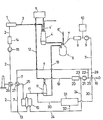
- a metallurgical plant according to the invention is illustrated in the drawing as a block diagram.
- the iron and steel mill comprises the coking plant designated 1 in the block diagram; from this, coke oven gas is drawn off via the line 2 and the solid coke reaches the blast furnace system 4 via the conveyor 3, of which only one blast furnace is shown schematically. The latter is also fed from ore task 5 with - if necessary sintered - piece ore. Blast furnace gas is discharged through line 4 '.
- the pig iron produced in the blast furnace is transferred to the converter steelworks 6, which can comprise several converters, and converted into raw steel. Scrap can also be added via conveyor line 6 '.
- the converter exhaust gas generated during the conversion (blowing) process is drawn off via line 7, and the crude steel produced is tapped from the converters.
- a gas cooling and cleaning device 8 and a compressor 9 are provided in the converter exhaust gas line 7. Furthermore, it is expedient to arrange a gas accumulator 10 in the exhaust gas line 7.
- a system 11 for the direct reduction of iron ore is combined with the described system parts, which - as shown - is advantageously designed as at least one shaft furnace.
- This direct reduction system 11 is fed from the ore feed 5 with piece ore or pellets via the line 12.
- the converter exhaust gas line 7 is combined at 13 with the coke oven gas line 2, in which a device 14 for cleaning and cooling the coke gas and a compressor 15 are provided, and the mixed gas is passed into a reformer 16.
- a mixed gas consisting mainly of CO and H 2 is generated from this mixed gas, which is introduced via the reducing gas line 17 into the direct reduction unit 11.
- the sponge iron produced is drawn off from the direct reduction system 11 and - if necessary in a hot briquetted state from a briquetting device (not shown) connected downstream of the reduction system - is inserted into the converter of the converter steelworks 6 by means of a transport device 18.
- the partially converted reducing gas, the exhaust gas from the direct reduction system or "top gas" from the head of the direct reduction system 11 is discharged through the top gas line 19, into which a gas cooling and purification unit 20 and a compressor 21 are installed in the exemplary embodiment shown. After compression in the compressor 21, part of the top gas can be fed into the converter exhaust gas via the line 22 shown in broken lines and fed to the reformer 16.
- the line 24 branching off at 23 brings cleaned top gas to the reformer 16, where it is expediently burned to heat the catalyst tubes of the reformer.
- the heat content of the combustion gases discharged from the reformer through line 25 is also used in the recuperators 26 and 27 for preheating the coke oven gases in line 2 and the converter exhaust gases in line 7.
- the converter exhaust gas line 7 can be connected to the top gas line 19 via an admixing line 28, wherein the proportions of the gases supplied through the recycle gas line 30 leading away from the mixing head 29 and through the reducing gas line 17 to the direct reduction system 11 can be regulated in a mixing head 29 .
- a device 31 for separating C0 2 (deacidification) from the cleaned and compressed top gas, optionally mixed with converter exhaust gas, and for preheating the deacidified gas mixture is installed in the recycle gas line 30.
- Purified top gas can be supplied from line 24 through branch line 32 to device 31 for the purpose of heating.
- the plants combined to form such a steelworks can have the following capacities, for example for the production of 4.2.106 tpd crude steel:
- Net means total production minus self-consumption.
- Typical compositions of the gases produced in the iron and steel works can be seen from the following table:
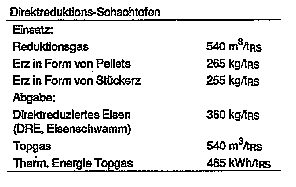
- the following exemplary embodiment serves for further explanation and is calculated for the production of 1 t of crude steel (RS) using an integrated steelworks of the above-described operating mode.
- the starting materials or products had the following composition:
Abstract
Description
Die Erfindung betrifft ein integriertes Hüttenwerk, umfassend eine Kokerei, eine Hochofenanlage, ein Konverterstahlwerk und eine Anlage zur Direktreduktion von Eisenerz, wobei eine Koksofengasleitung aus der Kokerei mit der Anlage zur Direktreduktion von Eisenerz leitungsmäßig verbunden ist, sowie ein Verfahren zum Betrieb eines solchen integrierten Hüttenwerkes.The invention relates to an integrated iron and steel mill, comprising a coking plant, a blast furnace system, a converter steelworks and a plant for the direct reduction of iron ore, a coke oven gas line from the coking plant being connected to the plant for the direct reduction of iron ore, and a method for operating such an integrated iron and steel works .
Bei der Herstellung -von Stahl nach dem Sauerstoffblasverfahren -in Sauerstoffaufblaskonvertern, in bodenblasenden Konvertern oder in Konvertern, bei denen diese Blasarten kombiniert angewendet werden können, unter teilweisem Einsatz von eisenhaltigen Feststoffen, wird flüssiges Roheisen benötigt. Dieses wird in der Hochofenanlage mittels hochwertigem Hüttenkoks, welch letzterer aus der Kokerei geliefert wird, hergestellt. In Abhängigkeit von der Analyse und der fühlbaren Wärme des flüssigen Roheisens werden den Konvertern als Kühlmittel feste Eisenträger, insbesondere Schrott, zugesetzt, wobei die Zugabe von zugekauftem (sogenanntem Fremd-) Schrott mitunter den Nachteil mit sich bringt, daß unerwünschte, nicht entfernbare Begleitelemente in den erzeugten Stahl eingebracht werden.When producing steel using the oxygen blowing process, in oxygen inflation converters, in bottom blowing converters or in converters in which these types of blowing can be used in combination, with the partial use of ferrous solids, liquid pig iron is required. This is produced in the blast furnace system using high-quality cottage coke, the latter of which is supplied from the coking plant. Depending on the analysis and the sensible heat of the liquid pig iron, solid iron carriers, in particular scrap, are added to the converters as coolants, whereby the addition of purchased (so-called foreign) scrap sometimes has the disadvantage that undesirable, non-removable accompanying elements are present the steel produced can be introduced.
Beim Betrieb von Hüttenwerken dieser Art entstehen große Mengen teilweise hochwertiger sogenannter Kuppelgase, wie Koksofengas und die Konverterabgase, welche Kuppelgase bisher nur teilweise genützt wurden, z.B. für Heizzwecke, zur Erzeugung von Wasserdampf oder - mit nur geringem Wirkungsgrad - zur Erzeugung von Strom.When operating smelters of this type, large quantities of partially high-quality so-called dome gases, such as coke oven gas and the converter exhaust gases, which dome gases have only been used to date, e.g. for heating purposes, for the generation of water vapor or - with only low efficiency - for the generation of electricity.
Eine Erhöhung der Menge des erzeugten Stahles ohne Kapazitätserweiterung der Hochofenanlage und ohne durch Schrott verursachte Probleme ist bei einer Anlage der eingangs beschriebenen Art, die aus Stahl und Eisen 95 (1975) Nr. 3, Seiten 91 bis 99 bekannt ist, gegeben.An increase in the amount of steel produced without expanding the capacity of the blast furnace system and without problems caused by scrap is given in a system of the type described at the outset, which is known from Stahl und Eisen 95 (1975) No. 3, pages 91 to 99.
Die Erfindung bezweckt eine Weiterentwicklung einer Anlage dieser Art dahingehend, daß der spezifische Energieverbrauch pro Tonne erzeugten Rohstahles, das ist die pro Tonne Rohstahl benötigte Menge an Primärenergie, reduziert ist. Insbesondere sollen die anfallenden Kuppelgase, nämlich das . Koksofengas und die Konverterabgase, mit besserem Wirkungsgrad nutzbar gemacht werden.The invention aims to further develop a plant of this type in such a way that the specific energy consumption per ton of crude steel produced, that is the amount of primary energy required per ton of crude steel, is reduced. In particular, the resulting coupling gases, namely the. Coke oven gas and the converter exhaust gases can be used with better efficiency.
Diese Aufgabe wird erfindungsgemäß dadurch gelöst, daß Leitungen für das Abgas aus den Konvertern und die Koksofengasleitung an einen Reformer zur Erzeugung von hauptsächlich CO und H2 enthaltendem Reduktionsgas angeschlossen sind und der Reformer über eine Reduktionsgasleitung mit der Direktreduktionsanlage verbunden ist.This object is achieved in that lines for the exhaust gas from the converters and the coke oven gas line are connected to a reformer for the production of mainly CO and H 2 containing reducing gas and the reformer is connected via a reducing gas line to the direct reduction system.
Die Direktreduktionsanlage kann insbesondere einen oder mehrere Schachtöfen umfassen. Es können jedoch auch andere bekannte Reduktionsaggregate, wie Wirbelschicht- und Wirbelbettreaktoren, verwendet werden.The direct reduction system can in particular comprise one or more shaft furnaces. However, other known reduction units, such as fluidized bed and fluidized bed reactors, can also be used.
Das im Koksofenabgas enthaltene Methan wird im Reformer mit dem im Konverterabgas enthaltenen C02 und Wasserdampf nach den Gleichungen
![]()
![]()
![]()
![]()
![]()
![]()
In den Abgasleitungen von den Konvertern zum Reformer ist vorteilhaft ein Gasspeicherbehälter angeordnet.A gas storage tank is advantageously arranged in the exhaust gas lines from the converters to the reformer.
Das aus den Konvertern beim Blasen diskontinuierlich anfallende Abgas wird in dem Gasspeicher-oder Pufferbehälter gesammelt und kann kontinuierlich an den Reformer abgegeben werden.The exhaust gas which is obtained discontinuously from the converters during blowing is collected in the gas storage or buffer tank and can be continuously released to the reformer.
Mehrere Konverter können auch in zeitlich zueinander versetzten Blaszyklen betrieben werden, um ohne Unterbrechung Konverterabgas für den Reformer verfügbar zu haben.Several converters can also be operated in time-shifted blowing cycles in order to have converter exhaust gas available for the reformer without interruption.
Ein Verfahren zum Betrieb eines integrierten Hüttenwerkes mit einer Kokerei, einer Hochofenanlage, einem Konverterstahlwerk und einer Anlage zur Direktreduktion von Eisenerz, wobei Koksofengas aus der Kokerei der Anlage zur Direktreduktion von Eisenerz zugeführt wird, ist dadurch gekennzeichnet, daß das Abgas aus den Konvertern und Koksofengas in einem Reformer zu hauptsächlich CO und H2 enthaltendem Reduktionsgas umgewandelt und der Direktreduktionsanlage zugeleitet wird und daß der in der Direktreduktionsanlage erzeugte Eisenschwamm in heißem Zustand in die Konverter eingesetzt wird.A method for operating an integrated steelworks with a coking plant, a blast furnace plant, a converter steel plant and a plant for the direct reduction of iron ore, wherein coke oven gas from the coking plant is fed to the plant for the direct reduction of iron ore, is characterized in that the exhaust gas from the converters and coke oven gas converted in a reformer to mainly CO and H 2 containing reducing gas and fed to the direct reduction system and that the sponge iron produced in the direct reduction system is used in the converter in a hot state.
Auf diese Weise wird dem flüssigen Roheisen in den Konvertern zum Schmelzen des Eisenschwammes nur eine vergleichsweise geringe Wärmemenge entzogen. Der heiße Eisenschwamm ersetzt einen Teil des Roheisens und/oder des Schrottes.In this way, only a comparatively small amount of heat is extracted from the liquid pig iron in the converters for melting the sponge iron. The hot sponge iron replaces part of the pig iron and / or scrap.
Vorzugsweise werden auch feste Kohlenstoffträger in die in den Konvertern vorliegende Metallschmelze eingebracht, um noch enthaltene Eisenoxidreste zu reduzieren und den gewünschten Gehalt an Kohlenstoff einzustellen.Solid carbon carriers are preferably also introduced into the metal melt present in the converters in order to reduce iron oxide residues still present and to set the desired carbon content.
Nach einer weiteren Ausführungsform des erfindungsgemäßen Verfahrens werden das vom Kopf der Direktreduktionsanlage abgezogene, teilweise umgesetzte Reduktionsgas und gegebenenfalls ein Teil des Abgases aus den Konvertern weitgehend vom enthaltenen Kohlendioxid befreit und das auf diese Weise erhaltene, entsäuerte Gasgemisch wird dem Reduktionsgas als Kreislaufgas zugemischt. Durch diese Maßnahmen kann die Menge an erzeugtem Eisenschwamm erhöht werden, ohne gleichzeitig mehr Koksofengas zu benötigen. Da mehr Eisenschwamm anfällt, ist es folglich möglich, die Menge an zuzusetzendem Schrott noch weiter zu verringern.According to a further embodiment of the method according to the invention, the partially converted reducing gas drawn off from the head of the direct reduction system and, if appropriate, part of the exhaust gas from the converters are largely freed of the carbon dioxide present, and that on the The deacidified gas mixture obtained in this way is mixed with the reducing gas as a recycle gas. These measures can increase the amount of sponge iron produced without simultaneously requiring more coke oven gas. As a result, since more sponge iron is produced, it is possible to reduce the amount of scrap to be added even further.
Ein erfindungsgemäßes Hüttenwerk ist in der Zeichnung als Blockschema veranschaulicht.A metallurgical plant according to the invention is illustrated in the drawing as a block diagram.
Das Hüttenwerk umfaßt die im Blockschema mit 1 bezeichnete Kokerei; von dieser wird über die Leitung 2 Koksofengas abgezogen und der-feste Koks gelangt über den Förderer 3 in die Hochofenanlage 4, von der lediglich ein Hochofen schematisch dargestellt ist. Letzerer wird aus der Erzaufgabe 5 auch mit - gegebenenfalls gesintertem - Stückerz beschickt. Hochofengas wird durch Leitung 4' abgeführt. Das im Hochofen erzeugte Roheisen wird in das Konverterstahlwerk 6, das mehrere Konverter umfassen kann, übergeführt und in Rohstahl umgewandelt. Über Förderleitung 6' kann auch Schrott zuchargiert werden. Das während des Umwandlungs-(Blas-)Prozesses entstehende Konverterabgas wird über die Leitung 7 abgezogen, der erzeugte Rohstahl wird aus den Konvertern abgestochen. In der Konverterabgasleitung 7 sind eine Gaskühl- und Reinigungseinrichtung 8 sowie ein Verdichter 9 vorgesehen. Weiters ist es zweckmäßig, in der Abgasleitung 7 einen Gasspeicher 10 anzuordnen.The iron and steel mill comprises the coking plant designated 1 in the block diagram; from this, coke oven gas is drawn off via the
Erfindungsgemäß ist mit den bechriebenen Anlageteilen eine Anlage 11 zur Direktreduktion von Eisenerz kombiniert, die - wie dargestellt - vorteilhaft als wenigstens en Schachtofen ausgebildet ist. Diese Direktreduktionsanlage 11 wird über die Leitung 12 von der Erzaufgabe 5 mit Stückerz oder Pellets beschickt. Die Konverterabgasleitung 7 wird bei 13 mit der Koksofengasleitung 2, in welcher eine Einrichtung 14 zur Koksgasreinigung und -kühlung sowie ein Verdichter 15 vorgesehen sind, vereinigt und das Mischgas wird in einen Reformer 16 geleitet. Im Reformer wird aus diesem Mischgas ein hauptsächlich aus CO und H2 bestehendes Reduktionsgas erzeugt, welches über die Reduktionsgasleitung 17 in die Direktreduktionsalage 11 eingeleitet wird. Der entstandene Eisenschwamm wird aus der Direktreduktionsanlage 11 abgezogen und - gegebenenfalls in heiß brikettiertem Zustand aus einer der Reduktionsanlage nachgeschalteten, nicht dargestellten Brikettiereinrichtung - mittels einer Transportvorrichtung 18 in die Konverter des Konverterstahlwerkes 6 eingesetzt. Das teilweise umgesetzte Reduktionsgas, das Abgas aus der Direktreduktionsanlage oder "top-gas" vom Kopf der Direktreduktionsanlage 11 wird durch die Topgasleitung 19 abgeführt, in welche im gezeigten Ausführungsbeispiel ein Gaskühl- und -reinigungsaggregat 20 sowie ein Verdichter 21 eingebaut sind. Ein Teil des Topgases kann nach Verdichtung im Verdichter 21 über die strichliert eingezeichnete Leitung 22 in die Konverterabgas führende Leitung 7 eingespeist und dem Reformer 16 zugeführt werden. Die bei 23 abzweigende Leitung 24 bringt gereinigtes Topgas zum Reformer 16, wo es zweckmäßig zur Beheizung der Katalysatorrohre des Reformers verbrannt wird. Der Wärmeinhalt der durch Leitung 25 aus dem Reformer abgeführten Verbrennungsgase wird gemäß der gezeigten Ausführungsform in den Rekuperatoren 26 und 27 noch zur Vorwärmung der Koksofengase in Leitung 2 sowie der Konverterabgase in Leitung 7 ausgenützt.According to the invention, a
Nach einer gleichfalls strichliert dargestellten Variante kann die Konverterabgasleitung 7 über eine Zumischleitung 28 mit der Topgasleitung 19 verbunden sein, wobei in einem Mischkopf 29 die Mengenanteile der durch die vom Mischkopf 29 wegführende Kreislaufgasleitung 30 und durch die Reduktionsgasleitung 17 der Direktreduktionsanlage 11 zugeführten Gase geregelt werden können. In die Kreislaufgasleitung 30 ist eine Einrichtung 31 zur Abtrennung von C02 (Entsäuerung) aus dem gereinigten und verdichteten, gegebenenfalls mit Konverterabgas vermischten Topgas sowie zur Vorwärmung des entsäuerten Gasgemisches eingebaut. Zum Zweck der Beheizung kann gereinigtes Topgas aus Leitung 24 durch Zweigleitung 32 der Einrichtung 31 zugeführt werden.According to a variant also shown in broken lines, the converter
In den einzelnen Leitungen können des weiteren nicht dargestellte Absperr-, Umlenk- und Regelorgane vorgesehen sein.Shut-off, deflection and control elements (not shown) can also be provided in the individual lines.
Aus der folgenden Beschreibung sind weitere Einzelheiten hinsichtlich des Aufbaues und des Betreibes des erfindungsgemäßen integrierten Hüttenwerkes zu entnehmen.From the following description further details regarding the construction and operation of the integrated steel mill according to the invention can be found.
Die zu einem solchen Hüttenwerk vereinigten Anlagen können, beispielsweise zur Erzeugung von 4,2.106 jato Rohstahl, folgende Kapazitäten aufweisen:

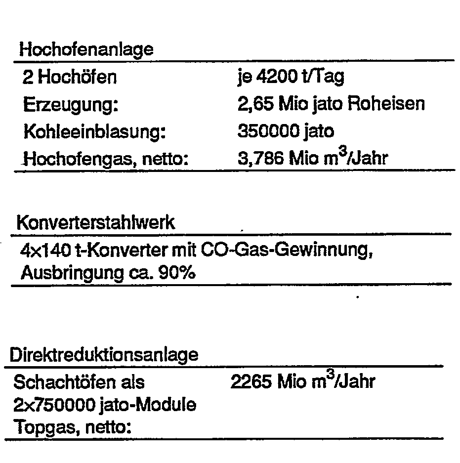
Sämtliche Volumsangaben beziehen sich auf den Normalzustand der Gase.All volume data refer to the normal state of the gases.
"Netto" bedeutet Gesamterzeugung abzüglich Eigenverbrauch."Net" means total production minus self-consumption.
Typische Zusammensetzungen der im Hüttenwerk erzeugten Gase sind aus der folgenden Tabelle zu ersehen:

Beispiel:
- Mengen- und Energiebilanz jedes Anlagenteiles:
 Hochofengas wird zum Teil im Hüttenwerk selbst verfeuert (Vorwärmeöfen), zum Teil in einem Kraftwerk verstromt.


- Quantity and energy balance of each plant part: Blast furnace gas is partly burned in the iron and steel mill itself (preheating furnaces) and partly turned into electricity in a power plant.
Die Einsatzstoffe bzw. Produkte hatten folgende Zusammensetzung:

Selbstverständlich können erfindungsgemäß auch Einsatzstoffe mit von den angegebenen Analysenwerten abweichender Qualität verwendet werden.According to the invention, it is of course also possible to use feedstocks with a quality differing from the analytical values indicated.
Ein Vergleich der Energiebilanz für die Herstellung von 1 t Rohstahl in einem erfindungsgemäßen integrierten Hüttenwerk mit jener für ein herkömmliches Hüttenwerk, welches ohne Direktreduktionsanlage arbeitet, ergibt eine Verminderung des spezifischen (auf eine Tonne erzeugten Rohstahles bezogenen) Energieverbrauches von ca. 1,77 GJ (etwa 21,77 GJ/t Rohstahl konventionell gegenüber etwa 20,0 GJ/t Rohstahl gemäß obigem Beispiel).A comparison of the energy balance for the production of 1 t of crude steel in an integrated steel mill according to the invention with that for a conventional steel mill, which works without a direct reduction system, results in a reduction in the specific energy consumption (based on a ton of crude steel produced) of approx. 1.77 GJ ( about 21.77 GJ / t crude steel conventional compared to about 20.0 GJ / t crude steel according to the example above).
Claims (5)
Priority Applications (5)
| Application Number | Priority Date | Filing Date | Title |
|---|---|---|---|
| DE8686890130T DE3669534D1 (en) | 1986-05-07 | 1986-05-07 | INTEGRATED CABINET. |
| AT86890130T ATE51032T1 (en) | 1986-05-07 | 1986-05-07 | INTEGRATED METAL PLANT. |
| EP19860890130 EP0244551B1 (en) | 1986-05-07 | 1986-05-07 | Integrated metallurgical plant |
| US07/035,988 US4822411A (en) | 1986-05-07 | 1987-04-08 | Integrated steel mill arrangement |
| JP9426387A JP2701841B2 (en) | 1986-05-07 | 1987-04-15 | Integrated mill device and operation method thereof |
Applications Claiming Priority (1)
| Application Number | Priority Date | Filing Date | Title |
|---|---|---|---|
| EP19860890130 EP0244551B1 (en) | 1986-05-07 | 1986-05-07 | Integrated metallurgical plant |
Publications (2)
| Publication Number | Publication Date |
|---|---|
| EP0244551A1 EP0244551A1 (en) | 1987-11-11 |
| EP0244551B1 true EP0244551B1 (en) | 1990-03-14 |
Family
ID=8196566
Family Applications (1)
| Application Number | Title | Priority Date | Filing Date |
|---|---|---|---|
| EP19860890130 Expired - Lifetime EP0244551B1 (en) | 1986-05-07 | 1986-05-07 | Integrated metallurgical plant |
Country Status (5)
| Country | Link |
|---|---|
| US (1) | US4822411A (en) |
| EP (1) | EP0244551B1 (en) |
| JP (1) | JP2701841B2 (en) |
| AT (1) | ATE51032T1 (en) |
| DE (1) | DE3669534D1 (en) |
Cited By (3)
| Publication number | Priority date | Publication date | Assignee | Title |
|---|---|---|---|---|
| DE102013113950A1 (en) * | 2013-12-12 | 2015-06-18 | Thyssenkrupp Ag | Plant network for steelmaking and process for operating the plant network |
| DE102013113921A1 (en) * | 2013-12-12 | 2015-06-18 | Thyssenkrupp Ag | Plant network for steelmaking and process for operating the plant network |
| DE102013113958A1 (en) * | 2013-12-12 | 2015-06-18 | Thyssenkrupp Ag | Plant network for steelmaking and process for operating the plant network |
Families Citing this family (30)
| Publication number | Priority date | Publication date | Assignee | Title |
|---|---|---|---|---|
| AT396255B (en) * | 1991-09-19 | 1993-07-26 | Voest Alpine Ind Anlagen | Plant and process for producing pig iron and iron sponge |
| US5380352A (en) * | 1992-10-06 | 1995-01-10 | Bechtel Group, Inc. | Method of using rubber tires in an iron making process |
| US5259864A (en) * | 1992-10-06 | 1993-11-09 | Bechtel Group, Inc. | Method of disposing of environmentally undesirable material and providing fuel for an iron making process e.g. petroleum coke |
| US5429658A (en) * | 1992-10-06 | 1995-07-04 | Bechtel Group, Inc. | Method of making iron from oily steel and iron ferrous waste |
| US6197088B1 (en) | 1992-10-06 | 2001-03-06 | Bechtel Group, Inc. | Producing liquid iron having a low sulfur content |
| US5320676A (en) * | 1992-10-06 | 1994-06-14 | Bechtel Group, Inc. | Low slag iron making process with injecting coolant |
| US5354356A (en) * | 1992-10-06 | 1994-10-11 | Bechtel Group Inc. | Method of providing fuel for an iron making process |
| US5397376A (en) * | 1992-10-06 | 1995-03-14 | Bechtel Group, Inc. | Method of providing fuel for an iron making process |
| US5338336A (en) * | 1993-06-30 | 1994-08-16 | Bechtel Group, Inc. | Method of processing electric arc furnace dust and providing fuel for an iron making process |
| US5958107A (en) * | 1993-12-15 | 1999-09-28 | Bechtel Croup, Inc. | Shift conversion for the preparation of reducing gas |
| AT406481B (en) * | 1995-04-25 | 2000-05-25 | Voest Alpine Ind Anlagen | Liq. pig iron@ or steel prodn. with increased productivity - by producing sponge iron in redn. zone, feeding into melting zone with carbon@ and oxygen@-contg. gas, recycling obtd. redn. gas contg. hydrogen@ and carbon mon:oxide, etc. |
| AT406586B (en) * | 1995-04-25 | 2000-06-26 | Voest Alpine Ind Anlagen | Process for producing liquid pig iron or liquid primary steel products and sponge iron, and installation for carrying out the process |
| US20020047230A1 (en) * | 1997-07-07 | 2002-04-25 | Jgc Corporation | Method of operating multi-industry integrated complex for basic industrial plants |
| ATE234939T1 (en) * | 1998-06-10 | 2003-04-15 | Sms Demag Ag | METHOD AND SYSTEM FOR PRODUCING STEEL IN AN ELECTRIC STEEL FURNACE FILLED WITH LIQUID PIG IRON FROM A MINI BLASTY FURNACE AND LESS SCRAP |
| WO2000047780A2 (en) * | 1999-02-02 | 2000-08-17 | Hylsa, S.A. De C.V. | Method and apparatus for preheating of direct reduced iron used as feed to an electric arc furnace |
| DE19951191C2 (en) * | 1999-10-22 | 2001-08-23 | Thyssen Krupp Encoke Gmbh | Method and device for discharging hot raw gases which are formed when coking in the furnace chambers of a coke oven battery |
| MXPA05012242A (en) * | 2003-05-15 | 2006-02-08 | Hylsa Sa | Method and apparatus for improved use of primary energy sources in integrated steel plants. |
| UA82962C2 (en) * | 2005-12-02 | 2008-05-26 | Sms Demag Ag | Method and smelting unit for obtaining steel with high manganese and low carbon content |
| US8765087B2 (en) * | 2008-05-16 | 2014-07-01 | Jfe Steel Corporation | Method for reforming exhaust gas generated from metallurgical furnace, method for cooling exhaust gas and apparatus therefor |
| JP5064330B2 (en) * | 2008-08-11 | 2012-10-31 | 新日本製鐵株式会社 | Method for producing reduced iron and pig iron |
| WO2011099070A1 (en) * | 2010-02-10 | 2011-08-18 | 新日本製鐵株式会社 | Process for production of reduced iron, and process for production of pig iron |
| US9028585B2 (en) * | 2010-05-14 | 2015-05-12 | Midrex Technologies, Inc. | System and method for reducing iron oxide to metallic iron using coke oven gas and oxygen steelmaking furnace gas |
| US8496730B2 (en) | 2010-05-14 | 2013-07-30 | Midrex Technologies, Inc. | System and method for reducing iron oxide to metallic iron using coke oven gas and oxygen steelmaking furnace gas |
| US9127326B2 (en) | 2010-05-14 | 2015-09-08 | Midrex Technologies, Inc. | System and method for reducing iron oxide to metallic iron using natural gas |
| UA117374C2 (en) * | 2013-07-31 | 2018-07-25 | Мідрекс Текнолоджиз, Інк. | RESTORATION OF IRON TO METAL IRON WITH THE APPLICATION OF COX GAS AND GAS FROM A STEEL FURNITURE WITH OXYGEN SUPPLY |
| DE102013113933A1 (en) * | 2013-12-12 | 2015-06-18 | Thyssenkrupp Ag | Process for the production of synthesis gas in association with a metallurgical plant |
| DE102013113913A1 (en) * | 2013-12-12 | 2015-06-18 | Thyssenkrupp Ag | Plant network for steelmaking and process for operating the plant network |
| WO2016118474A1 (en) | 2015-01-20 | 2016-07-28 | Midrex Technologies, Inc. | Methods and systems for producing high carbon content metallic iron using coke over gas |
| JP6763227B2 (en) * | 2016-08-08 | 2020-09-30 | 日本製鉄株式会社 | Manufacturing method of reduced iron and manufacturing method of molten steel |
| IT202100026993A1 (en) * | 2021-10-20 | 2023-04-20 | Wurth Paul Sa | "PROCEDURE FOR THE OPERATION OF A STEEL PLANT, STEEL PLANT, AND PROCEDURE FOR CONVERSION OF A STEEL PLANT" |
Family Cites Families (10)
| Publication number | Priority date | Publication date | Assignee | Title |
|---|---|---|---|---|
| US3653874A (en) * | 1970-01-02 | 1972-04-04 | Koppers Co Inc | Production of metal pellets from metallic oxides |
| DE2112369B2 (en) * | 1971-03-15 | 1973-03-15 | Steag Ag, 4300 Essen | METHOD OF OPERATING A COOK OVEN BATTERY IN CONNECTION WITH A REDUCING GAS OR. SYNTHESIS REQUIRING PLANT |
| FR2174796A1 (en) * | 1972-03-10 | 1973-10-19 | Erim | Reducing ferrous minerals - using treated furnace mouth gases |
| IT1038230B (en) * | 1974-05-22 | 1979-11-20 | Krupp Gmbh | PROCEDURE FOR THE PRODUCTION OF STEEL |
| US4053301A (en) * | 1975-10-14 | 1977-10-11 | Hazen Research, Inc. | Process for the direct production of steel |
| DE2638348A1 (en) * | 1976-08-26 | 1978-07-13 | Didier Eng | PROCESS FOR PROCESSING COOKING GAS |
| SE415006B (en) * | 1978-03-07 | 1980-09-01 | Asea Ab | PUT THE APPLICATION OF ISOLATED POLYMER INSULATION ON A CABLE conductor |
| US4253867A (en) * | 1979-10-15 | 1981-03-03 | Hylsa, S.A. | Method of using a methane-containing gas for reducing iron ore |
| US4531973A (en) * | 1980-04-08 | 1985-07-30 | Nixon Ivor G | Metallurgical processes |
| DE3318005C2 (en) * | 1983-05-18 | 1986-02-20 | Klöckner CRA Technologie GmbH, 4100 Duisburg | Process for making iron |
-
1986
- 1986-05-07 EP EP19860890130 patent/EP0244551B1/en not_active Expired - Lifetime
- 1986-05-07 DE DE8686890130T patent/DE3669534D1/en not_active Expired - Fee Related
- 1986-05-07 AT AT86890130T patent/ATE51032T1/en not_active IP Right Cessation
-
1987
- 1987-04-08 US US07/035,988 patent/US4822411A/en not_active Expired - Fee Related
- 1987-04-15 JP JP9426387A patent/JP2701841B2/en not_active Expired - Lifetime
Cited By (3)
| Publication number | Priority date | Publication date | Assignee | Title |
|---|---|---|---|---|
| DE102013113950A1 (en) * | 2013-12-12 | 2015-06-18 | Thyssenkrupp Ag | Plant network for steelmaking and process for operating the plant network |
| DE102013113921A1 (en) * | 2013-12-12 | 2015-06-18 | Thyssenkrupp Ag | Plant network for steelmaking and process for operating the plant network |
| DE102013113958A1 (en) * | 2013-12-12 | 2015-06-18 | Thyssenkrupp Ag | Plant network for steelmaking and process for operating the plant network |
Also Published As
| Publication number | Publication date |
|---|---|
| ATE51032T1 (en) | 1990-03-15 |
| JPS62267409A (en) | 1987-11-20 |
| JP2701841B2 (en) | 1998-01-21 |
| DE3669534D1 (en) | 1990-04-19 |
| US4822411A (en) | 1989-04-18 |
| EP0244551A1 (en) | 1987-11-11 |
Similar Documents
| Publication | Publication Date | Title |
|---|---|---|
| EP0244551B1 (en) | Integrated metallurgical plant | |
| DE2401909C3 (en) | Process for the production of steel | |
| AT505401B1 (en) | PROCESS FOR THE MELTING OF CRUDE IRON WITH THE RETURN OF GAS GAS WITH THE ADDITION OF HYDROCARBONS | |
| EP0126391B1 (en) | Iron production method | |
| AT507113A1 (en) | METHOD AND APPARATUS FOR ENERGY AND CO2 EMISSION OPTIMIZED IRON PRODUCTION | |
| EP3080307B1 (en) | Method for generating synthesis gas in conjunction with a smelting works | |
| AT511892B1 (en) | METHOD FOR THE TREATMENT OF EXHAUST GASES FROM PLANTS FOR THE PRODUCTION OF RAW CHEMISTRY AND / OR SYNTHESEGAS | |
| DE1783180A1 (en) | METHOD AND DEVICE FOR REDUCING IRON ORE | |
| WO2015086154A1 (en) | Plant combination for producing steel and method for operating the plant combination | |
| DE3024977A1 (en) | METHOD FOR PRODUCING REACTION GAS | |
| DD153701A5 (en) | METHOD AND APPARATUS FOR REDUCING IRON OXIDE TO METALIZED IRON | |
| DE3628102C2 (en) | ||
| AT406380B (en) | METHOD FOR PRODUCING LIQUID GUT IRON OR LIQUID STEEL PRE-PRODUCTS AND SYSTEM FOR IMPLEMENTING THE METHOD | |
| WO2019233934A1 (en) | Plant complex for producing steel and a method for operating the plant complex | |
| WO2017186782A1 (en) | Method for producing liquid pig iron | |
| EP2714942B1 (en) | Reduction of metal oxides using a gas stream containing both hydrocarbon and hydrogen | |
| DE102006048601A1 (en) | Method and device for producing molten material | |
| DE680605C (en) | Method of making sponge iron | |
| WO1993020245A1 (en) | Combined process for generating metallurgical coke and sponge iron | |
| DE102021112781A1 (en) | Process for producing steel in an integrated steel works | |
| DE2710106A1 (en) | METHOD FOR PRODUCING LIQUID PIG IRON | |
| WO2022073751A1 (en) | Method for producing pig iron in a shaft furnace | |
| AT407055B (en) | METHOD FOR PRODUCING LIQUID PIG IRON | |
| DE102021122351A1 (en) | Process for the production of an iron melt | |
| DE581869C (en) | Process for the production of iron in a shaft furnace |
Legal Events
| Date | Code | Title | Description |
|---|---|---|---|
| PUAI | Public reference made under article 153(3) epc to a published international application that has entered the european phase |
Free format text: ORIGINAL CODE: 0009012 |
|
| AK | Designated contracting states |
Kind code of ref document: A1 Designated state(s): AT BE CH DE FR GB IT LI LU NL SE |
|
| 17P | Request for examination filed |
Effective date: 19871203 |
|
| RTI1 | Title (correction) | ||
| 17Q | First examination report despatched |
Effective date: 19881227 |
|
| RAP1 | Party data changed (applicant data changed or rights of an application transferred) |
Owner name: VOEST-ALPINE INDUSTRIEANLAGENBAU GESELLSCHAFT M.B. |
|
| GRAA | (expected) grant |
Free format text: ORIGINAL CODE: 0009210 |
|
| AK | Designated contracting states |
Kind code of ref document: B1 Designated state(s): AT BE CH DE FR GB IT LI LU NL SE |
|
| REF | Corresponds to: |
Ref document number: 51032 Country of ref document: AT Date of ref document: 19900315 Kind code of ref document: T |
|
| REF | Corresponds to: |
Ref document number: 3669534 Country of ref document: DE Date of ref document: 19900419 |
|
| ET | Fr: translation filed | ||
| ITF | It: translation for a ep patent filed |
Owner name: SOCIETA' ITALIANA BREVETTI S.P.A. |
|
| GBT | Gb: translation of ep patent filed (gb section 77(6)(a)/1977) | ||
| PLBI | Opposition filed |
Free format text: ORIGINAL CODE: 0009260 |
|
| 26 | Opposition filed |
Opponent name: THYSSEN STAHL AG Effective date: 19901205 |
|
| NLR1 | Nl: opposition has been filed with the epo |
Opponent name: THYSSEN STAHL AG. |
|
| PLBN | Opposition rejected |
Free format text: ORIGINAL CODE: 0009273 |
|
| STAA | Information on the status of an ep patent application or granted ep patent |
Free format text: STATUS: OPPOSITION REJECTED |
|
| 27O | Opposition rejected |
Effective date: 19921103 |
|
| NLR2 | Nl: decision of opposition | ||
| ITTA | It: last paid annual fee | ||
| EPTA | Lu: last paid annual fee | ||
| EAL | Se: european patent in force in sweden |
Ref document number: 86890130.7 |
|
| PGFP | Annual fee paid to national office [announced via postgrant information from national office to epo] |
Ref country code: GB Payment date: 19990413 Year of fee payment: 14 |
|
| PGFP | Annual fee paid to national office [announced via postgrant information from national office to epo] |
Ref country code: FR Payment date: 19990419 Year of fee payment: 14 |
|
| PGFP | Annual fee paid to national office [announced via postgrant information from national office to epo] |
Ref country code: DE Payment date: 19990420 Year of fee payment: 14 |
|
| PGFP | Annual fee paid to national office [announced via postgrant information from national office to epo] |
Ref country code: CH Payment date: 19990421 Year of fee payment: 14 Ref country code: SE Payment date: 19990421 Year of fee payment: 14 |
|
| PGFP | Annual fee paid to national office [announced via postgrant information from national office to epo] |
Ref country code: AT Payment date: 19990422 Year of fee payment: 14 |
|
| PGFP | Annual fee paid to national office [announced via postgrant information from national office to epo] |
Ref country code: BE Payment date: 19990426 Year of fee payment: 14 |
|
| PGFP | Annual fee paid to national office [announced via postgrant information from national office to epo] |
Ref country code: NL Payment date: 19990427 Year of fee payment: 14 |
|
| PGFP | Annual fee paid to national office [announced via postgrant information from national office to epo] |
Ref country code: LU Payment date: 19990428 Year of fee payment: 14 |
|
| PG25 | Lapsed in a contracting state [announced via postgrant information from national office to epo] |
Ref country code: LU Free format text: LAPSE BECAUSE OF NON-PAYMENT OF DUE FEES Effective date: 20000507 Ref country code: GB Free format text: LAPSE BECAUSE OF NON-PAYMENT OF DUE FEES Effective date: 20000507 Ref country code: AT Free format text: LAPSE BECAUSE OF NON-PAYMENT OF DUE FEES Effective date: 20000507 |
|
| PG25 | Lapsed in a contracting state [announced via postgrant information from national office to epo] |
Ref country code: SE Free format text: LAPSE BECAUSE OF NON-PAYMENT OF DUE FEES Effective date: 20000508 |
|
| PG25 | Lapsed in a contracting state [announced via postgrant information from national office to epo] |
Ref country code: LI Free format text: LAPSE BECAUSE OF NON-PAYMENT OF DUE FEES Effective date: 20000531 Ref country code: CH Free format text: LAPSE BECAUSE OF NON-PAYMENT OF DUE FEES Effective date: 20000531 Ref country code: BE Free format text: LAPSE BECAUSE OF NON-PAYMENT OF DUE FEES Effective date: 20000531 |
|
| BERE | Be: lapsed |
Owner name: VOEST-ALPINE INDUSTRIEANLAGENBAU G.M.B.H. Effective date: 20000531 |
|
| PG25 | Lapsed in a contracting state [announced via postgrant information from national office to epo] |
Ref country code: NL Free format text: LAPSE BECAUSE OF NON-PAYMENT OF DUE FEES Effective date: 20001201 |
|
| GBPC | Gb: european patent ceased through non-payment of renewal fee |
Effective date: 20000507 |
|
| REG | Reference to a national code |
Ref country code: CH Ref legal event code: PL |
|
| EUG | Se: european patent has lapsed |
Ref document number: 86890130.7 |
|
| PG25 | Lapsed in a contracting state [announced via postgrant information from national office to epo] |
Ref country code: FR Free format text: LAPSE BECAUSE OF NON-PAYMENT OF DUE FEES Effective date: 20010131 |
|
| NLV4 | Nl: lapsed or anulled due to non-payment of the annual fee |
Effective date: 20001201 |
|
| PG25 | Lapsed in a contracting state [announced via postgrant information from national office to epo] |
Ref country code: DE Free format text: LAPSE BECAUSE OF NON-PAYMENT OF DUE FEES Effective date: 20010301 |
|
| REG | Reference to a national code |
Ref country code: FR Ref legal event code: ST |
|
| PG25 | Lapsed in a contracting state [announced via postgrant information from national office to epo] |
Ref country code: IT Free format text: LAPSE BECAUSE OF NON-PAYMENT OF DUE FEES;WARNING: LAPSES OF ITALIAN PATENTS WITH EFFECTIVE DATE BEFORE 2007 MAY HAVE OCCURRED AT ANY TIME BEFORE 2007. THE CORRECT EFFECTIVE DATE MAY BE DIFFERENT FROM THE ONE RECORDED. Effective date: 20050507 |