EP0244517B1 - Improved knife - Google Patents
Improved knife Download PDFInfo
- Publication number
- EP0244517B1 EP0244517B1 EP86303232A EP86303232A EP0244517B1 EP 0244517 B1 EP0244517 B1 EP 0244517B1 EP 86303232 A EP86303232 A EP 86303232A EP 86303232 A EP86303232 A EP 86303232A EP 0244517 B1 EP0244517 B1 EP 0244517B1
- Authority
- EP
- European Patent Office
- Prior art keywords
- blade
- handle
- support member
- knife
- knife according
- Prior art date
- Legal status (The legal status is an assumption and is not a legal conclusion. Google has not performed a legal analysis and makes no representation as to the accuracy of the status listed.)
- Expired
Links
- 230000015572 biosynthetic process Effects 0.000 claims 2
- 230000000063 preceeding effect Effects 0.000 claims 1
- 230000001133 acceleration Effects 0.000 description 2
- 230000006835 compression Effects 0.000 description 1
- 238000007906 compression Methods 0.000 description 1
- 238000010276 construction Methods 0.000 description 1
- 230000006378 damage Effects 0.000 description 1
- 210000003414 extremity Anatomy 0.000 description 1
- 230000005484 gravity Effects 0.000 description 1
- 230000035945 sensitivity Effects 0.000 description 1
- 238000009987 spinning Methods 0.000 description 1
- 239000004753 textile Substances 0.000 description 1
- 210000003813 thumb Anatomy 0.000 description 1
Images
Classifications
-
- B—PERFORMING OPERATIONS; TRANSPORTING
- B26—HAND CUTTING TOOLS; CUTTING; SEVERING
- B26B—HAND-HELD CUTTING TOOLS NOT OTHERWISE PROVIDED FOR
- B26B5/00—Hand knives with one or more detachable blades
- B26B5/001—Hand knives with one or more detachable blades with blades being slid out of handle immediately prior to use
- B26B5/003—Hand knives with one or more detachable blades with blades being slid out of handle immediately prior to use comprising retraction means for the blade or the blade holder
-
- B—PERFORMING OPERATIONS; TRANSPORTING
- B26—HAND CUTTING TOOLS; CUTTING; SEVERING
- B26B—HAND-HELD CUTTING TOOLS NOT OTHERWISE PROVIDED FOR
- B26B1/00—Hand knives with adjustable blade; Pocket knives
- B26B1/08—Hand knives with adjustable blade; Pocket knives with sliding blade
Definitions
- This invention concerns a knife of the kind (hereinafter termed 'of the kind referred to') comprising a blade and handle.
- the worker may be applying a force of such magnitude (c 150 N) that the knife, at the moment of slipping, can move with an acceleration 10 times that of gravity.
- a knife is known from GB-A-649 406 having a blade extendible for use from a handle, but which is retracted into the handle each time pressure thereon through cutting is removed. This document is the base of the preamble of claim 1.
- a knife comprising a blade and a handle the blade being arranged for sliding movement between a forward or operative position wherein it extends outwardly from the handle and a rearward or retracted position wherein the blade is located wholly within the handle, the blade being carried by a support member extending longitudinally of the handle and spring means between said support member and the handle serving to urge the blade to its rearward or retracted position, characterised by a member acting as an inertial mass movably located within the handle and engageable with said support member by detent means to latch same to hold the blade in its forward or operative position against the action of said spring means, the arrangement being such that violent movement of the knife at least with the cutting edge of the blade in a leading attitute causes relative movement between the mass and support member to break the engagement of the detent means to cause automatic retraction of the blade into the handle.
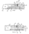
- the first form of knife comprises a handle 10 of hollow box-like construction and a blade 11 on the forward end of a tang 12.
- the blade 11 and tang 12 are slidable axially within the handle 10 to enable the blade 11 to be moved from an operative position wherein its cutting edge 11 a extends outwardly from the forward end of the handle ( Figure 1) to an inoperative or safe position wherein the blade 11 is fully retracted into the handle 10 ( Figure 2).
- a tension spring 13 has its opposite ends anchored to the blade 11 and the rear of the handle 10 respectively and acts to urge the blade 10 into its inoperative or safe position.
- the blade 11 may be slid into its operative position by pushing on the end of the tang 12 which projects rearwardly from the handle 10 and there locked in position by engagement of a latch 14 projecting from the tang 12 with a detent 15 in a heavy arm 16 pivotally connected with the handle 10 at 17 and extending generally parallel with the tang 12.
- the arm In use if the body of the knife accelerates violently in the plane of movement of the arm 16 with the cutting edge of the blade in a leading attitude, the arm, owing to its inertia, moves relative to the tang 12 thus releasing the latch and retracting the blade. Equally the latch may be released to retract the blade 11 for safe storage simply by a sharp rap on the handle 10 of the knife.
- the sensitivity of the system may be engineered by appropriate geometry but day to day adjustments may made by adjusting the force exerted on the arm 16 by a compression spring 18 by means of a grub screw 19.
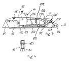
- the second form of knife comprises a handle 110 formed from two shell-like halves 111 and 112 which can be joined by screws at 113 and 114 on a longitudinal central plane of the handle 110 to form a box-like enclosure which houses the working parts of the knife.
- the knife includes a blade 115, which is a replaceable item, and which is clamped between support plates 116 by means of a screw 117. To gain access to screw 117 for blade replacement purposes it is necessary to separate the handle halves 111 and 112.
- One of the support plates 116 is connected to or integrally formed with a rearwardly projecting tang-like member 118 which has a longitudinally extending lateral recess 119 which houses a tension spring 120 whose forward end is anchored to the member 118 adjacent the plates 116 and whose rearward end is anchored to a transverse pin 121 extending between the halves 111 and 112 and through a longitudinally extending slot 122 in the member 118.
- the assembly including member 118 is slidable between a forward position wherein the blade 115 protrudes operatively from the handle 110 and a rearward position wherein the blade 115 is retracted to lie within the body of the handle 110.
- the spring 120 acts to urge the assembly including member 118 into the rearward position.
- a cranked lever 125 is pivotally mounted at the rear of the handle such that one of its arms 126 is accessible from without the handle for movement (in the direction of arrow X) against the action of a return torsion spring 127 to move the other of its arms 128 into engagement with an abutment surface at the rear end of member 118 to slide the assembly including member 118 forwardly to lock blade 115 protruding outwardly from handle 110 by a desired extent by engagement of one of a series of longitudinally spaced teeth 130 along the upper face of member 118 with a tooth 131 on the underside of a pivotally mounted weighted arm 132 mounted within the handle 110 above member 118.
- a spring 133 urges arm 132 towards member 118 and its strength is selected to ensure retraction of the assembly including member 118 and hence blade 115 when the handle 110 of the knife accelerates in the plane of movement of arm 132 with the cutting edge of the blade in a leading attitude at or above a predetermined rate because of relative movement between arm 132 and member 118 to disengage the tooth 131 from the tooth 130.
- the blade 115 may be moved to its retracted position by delivery of a sharp rap to the handle 110.
- a longitudinal thumb slide protruding from the underside of the kinfe handle may be provided for movement of the blade carrying assembly to its forward or operative position.
Landscapes
- Life Sciences & Earth Sciences (AREA)
- Forests & Forestry (AREA)
- Engineering & Computer Science (AREA)
- Mechanical Engineering (AREA)
- Knives (AREA)
Description
- This invention concerns a knife of the kind (hereinafter termed 'of the kind referred to') comprising a blade and handle.
- In industry many accidents are caused by hand knives. The most serious injuries occur when the blade, forcibly applied to the work-piece, slips and strikes the limbs or body of the user. In textile mills such accidents happen most frequently where residual thread is being stripped from bobbins or where entangled threads are being cut away from rollers on spinning machines.
- In such accidents the worker may be applying a force of such magnitude (c 150 N) that the knife, at the moment of slipping, can move with an
acceleration 10 times that of gravity. - It is an object of the present invention to provide a knife of the kind referred to which prevents or at least reduces the incidence of the kinds of accident mentioned above.
- A knife is known from GB-A-649 406 having a blade extendible for use from a handle, but which is retracted into the handle each time pressure thereon through cutting is removed. This document is the base of the preamble of
claim 1. - According to the present invention there is provided a knife comprising a blade and a handle the blade being arranged for sliding movement between a forward or operative position wherein it extends outwardly from the handle and a rearward or retracted position wherein the blade is located wholly within the handle, the blade being carried by a support member extending longitudinally of the handle and spring means between said support member and the handle serving to urge the blade to its rearward or retracted position, characterised by a member acting as an inertial mass movably located within the handle and engageable with said support member by detent means to latch same to hold the blade in its forward or operative position against the action of said spring means, the arrangement being such that violent movement of the knife at least with the cutting edge of the blade in a leading attitute causes relative movement between the mass and support member to break the engagement of the detent means to cause automatic retraction of the blade into the handle.
- The invention will be further apparent from the following description, with reference to the figures of the accompanying drawing, which show, by way of example only, two forms of knife of the kind referred to and embodying the invention. Of the drawings:-
- Figures 1 and 2
- are longitudinal cross-sections through the first form of knife with the blade thereof in its extended and retracted positions respectively.
- Figure 3
- is a longitudinal cross-section through the second form of knife with the blade thereof in an extended operative position;
- and Figure 4
- is an end view of the knife seen in the direction of arrow IV on Figure 3.
- Referring first to Figures 1 and 2 it will be seen that the first form of knife comprises a
handle 10 of hollow box-like construction and a blade 11 on the forward end of atang 12. The blade 11 andtang 12 are slidable axially within thehandle 10 to enable the blade 11 to be moved from an operative position wherein its cutting edge 11a extends outwardly from the forward end of the handle (Figure 1) to an inoperative or safe position wherein the blade 11 is fully retracted into the handle 10 (Figure 2). - A
tension spring 13 has its opposite ends anchored to the blade 11 and the rear of thehandle 10 respectively and acts to urge theblade 10 into its inoperative or safe position. - The blade 11 may be slid into its operative position by pushing on the end of the
tang 12 which projects rearwardly from thehandle 10 and there locked in position by engagement of alatch 14 projecting from thetang 12 with a detent 15 in a heavy arm 16 pivotally connected with thehandle 10 at 17 and extending generally parallel with thetang 12. - In use if the body of the knife accelerates violently in the plane of movement of the arm 16 with the cutting edge of the blade in a leading attitude, the arm, owing to its inertia, moves relative to the
tang 12 thus releasing the latch and retracting the blade. Equally the latch may be released to retract the blade 11 for safe storage simply by a sharp rap on thehandle 10 of the knife. - The sensitivity of the system may be engineered by appropriate geometry but day to day adjustments may made by adjusting the force exerted on the arm 16 by a
compression spring 18 by means of agrub screw 19. - Referring now to Figures 3 and 4, it will be seen that the second form of knife comprises a
handle 110 formed from two shell-like halves handle 110 to form a box-like enclosure which houses the working parts of the knife. - The knife includes a
blade 115, which is a replaceable item, and which is clamped betweensupport plates 116 by means of ascrew 117. To gain access toscrew 117 for blade replacement purposes it is necessary to separate thehandle halves - One of the
support plates 116 is connected to or integrally formed with a rearwardly projecting tang-like member 118 which has a longitudinally extendinglateral recess 119 which houses atension spring 120 whose forward end is anchored to themember 118 adjacent theplates 116 and whose rearward end is anchored to atransverse pin 121 extending between thehalves slot 122 in themember 118. - The
assembly including member 118 is slidable between a forward position wherein theblade 115 protrudes operatively from thehandle 110 and a rearward position wherein theblade 115 is retracted to lie within the body of thehandle 110. Thespring 120 acts to urge theassembly including member 118 into the rearward position. - A
cranked lever 125 is pivotally mounted at the rear of the handle such that one of itsarms 126 is accessible from without the handle for movement (in the direction of arrow X) against the action of areturn torsion spring 127 to move the other of itsarms 128 into engagement with an abutment surface at the rear end ofmember 118 to slide theassembly including member 118 forwardly to lockblade 115 protruding outwardly fromhandle 110 by a desired extent by engagement of one of a series of longitudinally spacedteeth 130 along the upper face ofmember 118 with atooth 131 on the underside of a pivotally mountedweighted arm 132 mounted within thehandle 110 abovemember 118. A spring 133urges arm 132 towardsmember 118 and its strength is selected to ensure retraction of theassembly including member 118 and henceblade 115 when thehandle 110 of the knife accelerates in the plane of movement ofarm 132 with the cutting edge of the blade in a leading attitude at or above a predetermined rate because of relative movement betweenarm 132 andmember 118 to disengage thetooth 131 from thetooth 130. Again theblade 115 may be moved to its retracted position by delivery of a sharp rap to thehandle 110. - It will be appreciated that it is not intended to limit the invention to the above example only, many variations, such as might readily occur to one skilled in the art, being possible, without departing from the scope thereof as defined by the appended claims.
- For example, a longitudinal thumb slide protruding from the underside of the kinfe handle may be provided for movement of the blade carrying assembly to its forward or operative position.
- Other means for detecting acceleration than that described may be used such as electronic transducer means, but a simple mechanical system is preferred on the grounds of reliability and cost.
Claims (9)
- A knife comprising a blade (11,115) and a handle (10,110) the blade being arranged for sliding movement between a forward or operative position wherein it extends outwardly from the handle (10,110) and a rearward or retracted position wherein the blade (11,115) is located wholly within the handle, the blade being carried by a support member (12,118) extending longitudinally of the handle and spring means (13,120) between said support member (12,118) and the handle serving to urge the blade (11,115) to its rearward or retracted position, characterised by a member acting as an inertial mass (16,132) movably located within the handle (10,110) and engageable with said support member (12,118) by detent means (15,131) to latch same to hold the blade (11,115) in its forward or operative position against the action of said spring means (13,120), the arrangement being such that violent movement of the knife at least with the cutting edge of the blade (11,115) in a leading attitute causes relative movement between the mass and support member (12,118) to break the engagement of the detent means (15,131) to cause automatic retraction of the blade (11,115) into the handle (10,110).
- A knife according to claim 1, wherein the inertial mass is comprised bu a pivotted lever.
- A knife according to claim 2, wherein the detent means comprises a tooth formation (15,131) on said lever engageable with a cooperating tooth formation (14,130) on said support member.
- A knife according to claim 3, wherein there are plurality of longitudinally spaced teeth (130) on the support member enabling the blade to be latched with a desired extent of protrusion.
- A knife according to any one of claims 2-4, wherein said lever is urged towards the support member by resilient means (18,133) which may be adjustable.
- A knife according to any preceding claim, including manually operable means (125) for sliding the support member and hence blade from its rearward or retracted position to its forward or operative position.
- A knife according to claim 6, wherein said manually operable means comprises a cranked lever which may be pivotted to bring one of its arms (128) to bear against the end of the tang-like member to push it forwardly.
- A knife according to claim 7, wherein the cranked lever may be operated against the action of return spring means (127) therefor.
- A knife according to any preceeding claim wherein the handle is comprised by two separable halves (111,112) which form a box-like enclosure for the working parts of the knife.
Priority Applications (2)
| Application Number | Priority Date | Filing Date | Title |
|---|---|---|---|
| AT86303232T ATE64710T1 (en) | 1986-04-29 | 1986-04-29 | KNIFE. |
| DE8686303232T DE3679987D1 (en) | 1986-04-29 | 1986-04-29 | KNIFE. |
Applications Claiming Priority (1)
| Application Number | Priority Date | Filing Date | Title |
|---|---|---|---|
| GB848432145A GB8432145D0 (en) | 1984-12-20 | 1984-12-20 | Knife |
Publications (2)
| Publication Number | Publication Date |
|---|---|
| EP0244517A1 EP0244517A1 (en) | 1987-11-11 |
| EP0244517B1 true EP0244517B1 (en) | 1991-06-26 |
Family
ID=10571476
Family Applications (1)
| Application Number | Title | Priority Date | Filing Date |
|---|---|---|---|
| EP86303232A Expired EP0244517B1 (en) | 1984-12-20 | 1986-04-29 | Improved knife |
Country Status (3)
| Country | Link |
|---|---|
| US (1) | US4769912A (en) |
| EP (1) | EP0244517B1 (en) |
| GB (2) | GB8432145D0 (en) |
Cited By (1)
| Publication number | Priority date | Publication date | Assignee | Title |
|---|---|---|---|---|
| DE4310037C1 (en) * | 1993-03-27 | 1993-12-09 | Beermann Kg Martor Argentax | Knife with automatically retractable blade - has capacitive acceleration sensor in hollow handle coupled to electromagnetic lock for unlatching spring returned blade when translatory or angular acceleration exceeds threshold. |
Families Citing this family (36)
| Publication number | Priority date | Publication date | Assignee | Title |
|---|---|---|---|---|
| GB2192358B (en) * | 1986-07-08 | 1989-12-20 | Shirley Inst The | Knife |
| US5125157A (en) * | 1991-03-08 | 1992-06-30 | Howard Durvyn M | Knife with removable implement |
| DE4200018C1 (en) * | 1992-01-02 | 1992-11-05 | Martor-Argentax E. H. Beermann Kg, 5650 Solingen, De | |
| DE4341360C1 (en) * | 1993-12-04 | 1994-08-18 | Beermann Kg Martor Argentax | Knife with an automatically acting retraction device for the knife blade outside its handle position |
| DE19507272C1 (en) * | 1995-03-03 | 1995-09-28 | Beermann Kg Martor Argentax | Knife, especially for cardboard, with blade holder |
| IT1276991B1 (en) * | 1995-10-24 | 1997-11-03 | Giuseppe Pilo | DISPOSABLE SURGICAL SCALPEL FOR SAFETY |
| EP0835728A1 (en) * | 1996-10-09 | 1998-04-15 | A. Eickhorn Gmbh + Co. Für Schneidwaren + Waffen Kg | Knife with falling out blade or the like |
| US6026574A (en) * | 1997-03-28 | 2000-02-22 | Ghavami; Bert | Cigar plug cutting apparatus |
| DE19732387A1 (en) * | 1997-07-25 | 1999-02-11 | Beermann Kg Martor Argentax | knife |
| US6085423A (en) * | 1999-03-19 | 2000-07-11 | Marifone; Anthony L. | Triggered spring ejectable blade sheathed knives |
| DE19915934C1 (en) * | 1999-04-09 | 1999-12-09 | Beermann Kg Martor Argentax | Hand knife with retractable blade |
| US6453564B1 (en) | 2000-11-06 | 2002-09-24 | Merrill R. Foley | Multi-function rescue tool |
| GB0207030D0 (en) * | 2002-03-25 | 2002-05-08 | Baker Martin Aircraft Co | Multi-axis "g" sensor |
| US7776027B2 (en) | 2002-07-11 | 2010-08-17 | Misonix, Incorporated | Medical handpiece with automatic power switching means |
| US8220160B2 (en) * | 2005-09-16 | 2012-07-17 | Adco Industries-Technologies, L.P. | Box cutter with grip-actuated blade extension |
| DE102005049411B3 (en) * | 2005-10-13 | 2007-03-01 | Martor Kg | Knife, has operation lug, held outside of blade bolt at base plate, where inner surfaces hold bolt in its closed position close to plate and release bolt for opening bolt and taking out knife blade |
| US7316070B2 (en) | 2005-11-15 | 2008-01-08 | Irwin Industrial Tool Company | Self-retracting utility knife |
| DE102005057213B3 (en) * | 2005-11-29 | 2007-03-22 | Martor Kg | Cutter for individual changeable steel strip blades has front end of housing round blade gap projecting and at obtuse angle to central longitudinal axis |
| US7827697B2 (en) * | 2006-01-23 | 2010-11-09 | Lake Ronald W | Low friction folding knife |
| US20070245569A1 (en) * | 2006-04-25 | 2007-10-25 | Hsiu-Man Yu Chen | Belt cutter with safety retractable blades |
| ATE514533T1 (en) * | 2007-04-16 | 2011-07-15 | Adco Ind A Subsidiary Of Dallco Marketing Inc | CUTTING RIGID AND SEMI-RIGID MATERIAL |
| GB0901651D0 (en) * | 2009-02-03 | 2009-03-11 | W A I Designs Ltd | Safety knife |
| WO2010096454A1 (en) * | 2009-02-19 | 2010-08-26 | Liqui-Box Corporation | Dual-blade film-cutting device |
| US8307556B2 (en) | 2009-06-19 | 2012-11-13 | ADCO Industries—Technologies, L.P. | Utility cutter |
| TWM394220U (en) * | 2010-03-24 | 2010-12-11 | jun-feng He | Safety utility knife |
| US9289904B2 (en) * | 2011-11-14 | 2016-03-22 | Grant Woodrow Hawk | Lock optional, spring assisted folding knife |
| CN108309404A (en) * | 2012-12-05 | 2018-07-24 | 佩恩布雷德公司 | Safe cutting equipment |
| US8782909B1 (en) | 2013-02-12 | 2014-07-22 | ADCO Industries—Technologies, L.P. | Utility cutter |
| CN103846958B (en) * | 2014-03-18 | 2015-12-09 | 诸暨中澳自动化设备有限公司 | A kind of two-freedom mechanical protection mechanism of cutting off tool and using method thereof |
| TWM511938U (en) * | 2015-08-21 | 2015-11-11 | 禾龍有限公司 | Spring-assisted tool that can open and fold the blade on the same side of the shank |
| US11097434B2 (en) * | 2017-12-21 | 2021-08-24 | Mark Gordon Hooper | Utility knife |
| US10427310B2 (en) * | 2017-12-23 | 2019-10-01 | Slice, Inc. | Cutting device |
| US12330321B2 (en) * | 2023-04-21 | 2025-06-17 | Deepak C. Chopra | Out-the-front double-action knife |
| US20250114955A1 (en) * | 2023-10-04 | 2025-04-10 | Kai U.S.A., Ltd. | Slider cartridge for out the front knife |
| US11999070B1 (en) * | 2023-10-17 | 2024-06-04 | Microtech Knives, Inc. | Pocket knife |
| US12005594B1 (en) * | 2024-01-20 | 2024-06-11 | Microtech Knives, Inc. | Pocket knife |
Family Cites Families (4)
| Publication number | Priority date | Publication date | Assignee | Title |
|---|---|---|---|---|
| GB649406A (en) * | 1948-09-14 | 1951-01-24 | Dunlop Rubber Co | An improved safety cutting knife |
| DE1272169B (en) * | 1965-09-08 | 1968-07-04 | Norbert Wietscher | Cutting device |
| US3999290A (en) * | 1976-03-15 | 1976-12-28 | Wood Jess W | Safety knife |
| ES237136Y (en) * | 1978-07-06 | 1979-01-16 | PERFECTED AUTOMATIC POCKET KNIFE. |
-
1984
- 1984-12-20 GB GB848432145A patent/GB8432145D0/en active Pending
-
1985
- 1985-12-10 GB GB08530435A patent/GB2169539B/en not_active Expired
-
1986
- 1986-04-29 EP EP86303232A patent/EP0244517B1/en not_active Expired
-
1987
- 1987-08-31 US US07/091,084 patent/US4769912A/en not_active Expired - Lifetime
Cited By (1)
| Publication number | Priority date | Publication date | Assignee | Title |
|---|---|---|---|---|
| DE4310037C1 (en) * | 1993-03-27 | 1993-12-09 | Beermann Kg Martor Argentax | Knife with automatically retractable blade - has capacitive acceleration sensor in hollow handle coupled to electromagnetic lock for unlatching spring returned blade when translatory or angular acceleration exceeds threshold. |
Also Published As
| Publication number | Publication date |
|---|---|
| GB8432145D0 (en) | 1985-01-30 |
| GB2169539A (en) | 1986-07-16 |
| EP0244517A1 (en) | 1987-11-11 |
| GB8530435D0 (en) | 1986-01-22 |
| GB2169539B (en) | 1987-11-25 |
| US4769912A (en) | 1988-09-13 |
Similar Documents
| Publication | Publication Date | Title |
|---|---|---|
| EP0244517B1 (en) | Improved knife | |
| EP0252711B1 (en) | Safety knife | |
| US6044562A (en) | Safety interlocking blade release mechanism for hand held cutting tools | |
| US5617635A (en) | Autoretracting box-cutting knife | |
| EP0676993B1 (en) | Safety utility knife | |
| US5442855A (en) | Pocket knife with lockable blade | |
| EP0673721A1 (en) | Device with automatic feeder for driving ribbon-mounted screws | |
| US8595942B2 (en) | Safe utility knife | |
| US20090277016A1 (en) | Utility knife with an auto-retractable blade | |
| WO2007087226A2 (en) | Folding tool with lockback mechanism | |
| EP2603358A2 (en) | Cutting tool | |
| EP0392069A1 (en) | Pocket-knife having a handle provided with a slidable blade | |
| CA2290322A1 (en) | Blade sharpener | |
| HK1024661B (en) | Knife with at least one guard | |
| HK1024661A1 (en) | Knife with at least one guard | |
| FI85115C (en) | Knivvässare | |
| CA1262206A (en) | Knife | |
| IE861143L (en) | Knife | |
| EP0638477B1 (en) | Bundling strap dispenser | |
| CN86104583A (en) | Improved blade | |
| JPH0312904B2 (en) | ||
| US6123001A (en) | Detonating cord cutter | |
| HK1125599A (en) | Folding tool with lockback mechanism | |
| CA2182295A1 (en) | Chain saw file angle guide | |
| EP0656247A1 (en) | Knife with automatic retraction device for the knife blade when it is no longer in its operating position |
Legal Events
| Date | Code | Title | Description |
|---|---|---|---|
| PUAI | Public reference made under article 153(3) epc to a published international application that has entered the european phase |
Free format text: ORIGINAL CODE: 0009012 |
|
| AK | Designated contracting states |
Kind code of ref document: A1 Designated state(s): AT BE CH DE FR GB IT LI LU NL SE |
|
| 17P | Request for examination filed |
Effective date: 19880415 |
|
| 17Q | First examination report despatched |
Effective date: 19890605 |
|
| RAP1 | Party data changed (applicant data changed or rights of an application transferred) |
Owner name: BRITISH TEXTILE TECHNOLOGY GROUP |
|
| GRAA | (expected) grant |
Free format text: ORIGINAL CODE: 0009210 |
|
| AK | Designated contracting states |
Kind code of ref document: B1 Designated state(s): AT BE CH DE FR GB IT LI LU NL SE |
|
| REF | Corresponds to: |
Ref document number: 64710 Country of ref document: AT Date of ref document: 19910715 Kind code of ref document: T |
|
| ITF | It: translation for a ep patent filed | ||
| REF | Corresponds to: |
Ref document number: 3679987 Country of ref document: DE Date of ref document: 19910801 |
|
| ET | Fr: translation filed | ||
| PGFP | Annual fee paid to national office [announced via postgrant information from national office to epo] |
Ref country code: AT Payment date: 19920310 Year of fee payment: 7 |
|
| PGFP | Annual fee paid to national office [announced via postgrant information from national office to epo] |
Ref country code: SE Payment date: 19920316 Year of fee payment: 7 |
|
| PG25 | Lapsed in a contracting state [announced via postgrant information from national office to epo] |
Ref country code: LU Free format text: LAPSE BECAUSE OF NON-PAYMENT OF DUE FEES Effective date: 19920430 |
|
| PLBE | No opposition filed within time limit |
Free format text: ORIGINAL CODE: 0009261 |
|
| STAA | Information on the status of an ep patent application or granted ep patent |
Free format text: STATUS: NO OPPOSITION FILED WITHIN TIME LIMIT |
|
| 26N | No opposition filed | ||
| PG25 | Lapsed in a contracting state [announced via postgrant information from national office to epo] |
Ref country code: AT Effective date: 19930429 |
|
| PG25 | Lapsed in a contracting state [announced via postgrant information from national office to epo] |
Ref country code: SE Effective date: 19930430 |
|
| EUG | Se: european patent has lapsed |
Ref document number: 86303232.2 Effective date: 19931110 |
|
| PGFP | Annual fee paid to national office [announced via postgrant information from national office to epo] |
Ref country code: BE Payment date: 19970313 Year of fee payment: 12 |
|
| PGFP | Annual fee paid to national office [announced via postgrant information from national office to epo] |
Ref country code: CH Payment date: 19970324 Year of fee payment: 12 |
|
| PGFP | Annual fee paid to national office [announced via postgrant information from national office to epo] |
Ref country code: NL Payment date: 19980324 Year of fee payment: 13 |
|
| PG25 | Lapsed in a contracting state [announced via postgrant information from national office to epo] |
Ref country code: LI Free format text: LAPSE BECAUSE OF NON-PAYMENT OF DUE FEES Effective date: 19980430 Ref country code: CH Free format text: LAPSE BECAUSE OF NON-PAYMENT OF DUE FEES Effective date: 19980430 Ref country code: BE Free format text: LAPSE BECAUSE OF NON-PAYMENT OF DUE FEES Effective date: 19980430 |
|
| BERE | Be: lapsed |
Owner name: BRITISH TEXTILE TECHNOLOGY GROUP Effective date: 19980430 |
|
| REG | Reference to a national code |
Ref country code: CH Ref legal event code: PL |
|
| PG25 | Lapsed in a contracting state [announced via postgrant information from national office to epo] |
Ref country code: NL Free format text: LAPSE BECAUSE OF NON-PAYMENT OF DUE FEES Effective date: 19991101 |
|
| NLV4 | Nl: lapsed or anulled due to non-payment of the annual fee |
Effective date: 19991101 |
|
| REG | Reference to a national code |
Ref country code: GB Ref legal event code: IF02 |
|
| PGFP | Annual fee paid to national office [announced via postgrant information from national office to epo] |
Ref country code: FR Payment date: 20050310 Year of fee payment: 20 |
|
| PGFP | Annual fee paid to national office [announced via postgrant information from national office to epo] |
Ref country code: GB Payment date: 20050314 Year of fee payment: 20 |
|
| PG25 | Lapsed in a contracting state [announced via postgrant information from national office to epo] |
Ref country code: IT Free format text: LAPSE BECAUSE OF NON-PAYMENT OF DUE FEES;WARNING: LAPSES OF ITALIAN PATENTS WITH EFFECTIVE DATE BEFORE 2007 MAY HAVE OCCURRED AT ANY TIME BEFORE 2007. THE CORRECT EFFECTIVE DATE MAY BE DIFFERENT FROM THE ONE RECORDED. Effective date: 20050429 |
|
| PGFP | Annual fee paid to national office [announced via postgrant information from national office to epo] |
Ref country code: DE Payment date: 20050524 Year of fee payment: 20 |
|
| PG25 | Lapsed in a contracting state [announced via postgrant information from national office to epo] |
Ref country code: GB Free format text: LAPSE BECAUSE OF EXPIRATION OF PROTECTION Effective date: 20060428 |
|
| REG | Reference to a national code |
Ref country code: GB Ref legal event code: PE20 |