EP0244505B1 - Work surface ganging clip - Google Patents
Work surface ganging clip Download PDFInfo
- Publication number
- EP0244505B1 EP0244505B1 EP86113476A EP86113476A EP0244505B1 EP 0244505 B1 EP0244505 B1 EP 0244505B1 EP 86113476 A EP86113476 A EP 86113476A EP 86113476 A EP86113476 A EP 86113476A EP 0244505 B1 EP0244505 B1 EP 0244505B1
- Authority
- EP
- European Patent Office
- Prior art keywords
- clip
- jaw
- ganging
- central web
- ganging clip
- Prior art date
- Legal status (The legal status is an assumption and is not a legal conclusion. Google has not performed a legal analysis and makes no representation as to the accuracy of the status listed.)
- Expired - Lifetime
Links
- 229910000922 High-strength low-alloy steel Inorganic materials 0.000 description 1
- 241000935061 Larrea Species 0.000 description 1
- 229910000700 SAE 1075 Inorganic materials 0.000 description 1
- 229910000639 Spring steel Inorganic materials 0.000 description 1
- 229910000831 Steel Inorganic materials 0.000 description 1
- 238000005452 bending Methods 0.000 description 1
- 238000004519 manufacturing process Methods 0.000 description 1
- 238000012986 modification Methods 0.000 description 1
- 230000004048 modification Effects 0.000 description 1
- 238000000465 moulding Methods 0.000 description 1
- 239000010959 steel Substances 0.000 description 1
- 230000000007 visual effect Effects 0.000 description 1
Images

Classifications
-
- F—MECHANICAL ENGINEERING; LIGHTING; HEATING; WEAPONS; BLASTING
- F16—ENGINEERING ELEMENTS AND UNITS; GENERAL MEASURES FOR PRODUCING AND MAINTAINING EFFECTIVE FUNCTIONING OF MACHINES OR INSTALLATIONS; THERMAL INSULATION IN GENERAL
- F16B—DEVICES FOR FASTENING OR SECURING CONSTRUCTIONAL ELEMENTS OR MACHINE PARTS TOGETHER, e.g. NAILS, BOLTS, CIRCLIPS, CLAMPS, CLIPS OR WEDGES; JOINTS OR JOINTING
- F16B2/00—Friction-grip releasable fastenings
- F16B2/02—Clamps, i.e. with gripping action effected by positive means other than the inherent resistance to deformation of the material of the fastening
- F16B2/06—Clamps, i.e. with gripping action effected by positive means other than the inherent resistance to deformation of the material of the fastening external, i.e. with contracting action
- F16B2/065—Clamps, i.e. with gripping action effected by positive means other than the inherent resistance to deformation of the material of the fastening external, i.e. with contracting action using screw-thread elements
-
- A—HUMAN NECESSITIES
- A47—FURNITURE; DOMESTIC ARTICLES OR APPLIANCES; COFFEE MILLS; SPICE MILLS; SUCTION CLEANERS IN GENERAL
- A47B—TABLES; DESKS; OFFICE FURNITURE; CABINETS; DRAWERS; GENERAL DETAILS OF FURNITURE
- A47B5/00—Suspended or hinged panels forming a table; Wall tables
-
- A—HUMAN NECESSITIES
- A47—FURNITURE; DOMESTIC ARTICLES OR APPLIANCES; COFFEE MILLS; SPICE MILLS; SUCTION CLEANERS IN GENERAL
- A47B—TABLES; DESKS; OFFICE FURNITURE; CABINETS; DRAWERS; GENERAL DETAILS OF FURNITURE
- A47B57/00—Cabinets, racks or shelf units, characterised by features for adjusting shelves or partitions
- A47B57/30—Cabinets, racks or shelf units, characterised by features for adjusting shelves or partitions with means for adjusting the height of detachable shelf supports
-
- F—MECHANICAL ENGINEERING; LIGHTING; HEATING; WEAPONS; BLASTING
- F16—ENGINEERING ELEMENTS AND UNITS; GENERAL MEASURES FOR PRODUCING AND MAINTAINING EFFECTIVE FUNCTIONING OF MACHINES OR INSTALLATIONS; THERMAL INSULATION IN GENERAL
- F16B—DEVICES FOR FASTENING OR SECURING CONSTRUCTIONAL ELEMENTS OR MACHINE PARTS TOGETHER, e.g. NAILS, BOLTS, CIRCLIPS, CLAMPS, CLIPS OR WEDGES; JOINTS OR JOINTING
- F16B2/00—Friction-grip releasable fastenings
- F16B2/02—Clamps, i.e. with gripping action effected by positive means other than the inherent resistance to deformation of the material of the fastening
- F16B2/06—Clamps, i.e. with gripping action effected by positive means other than the inherent resistance to deformation of the material of the fastening external, i.e. with contracting action
- F16B2/10—Clamps, i.e. with gripping action effected by positive means other than the inherent resistance to deformation of the material of the fastening external, i.e. with contracting action using pivoting jaws
-
- F—MECHANICAL ENGINEERING; LIGHTING; HEATING; WEAPONS; BLASTING
- F16—ENGINEERING ELEMENTS AND UNITS; GENERAL MEASURES FOR PRODUCING AND MAINTAINING EFFECTIVE FUNCTIONING OF MACHINES OR INSTALLATIONS; THERMAL INSULATION IN GENERAL
- F16B—DEVICES FOR FASTENING OR SECURING CONSTRUCTIONAL ELEMENTS OR MACHINE PARTS TOGETHER, e.g. NAILS, BOLTS, CIRCLIPS, CLAMPS, CLIPS OR WEDGES; JOINTS OR JOINTING
- F16B2200/00—Constructional details of connections not covered for in other groups of this subclass
- F16B2200/50—Flanged connections
- F16B2200/509—Flanged connections clamped
-
- Y—GENERAL TAGGING OF NEW TECHNOLOGICAL DEVELOPMENTS; GENERAL TAGGING OF CROSS-SECTIONAL TECHNOLOGIES SPANNING OVER SEVERAL SECTIONS OF THE IPC; TECHNICAL SUBJECTS COVERED BY FORMER USPC CROSS-REFERENCE ART COLLECTIONS [XRACs] AND DIGESTS
- Y10—TECHNICAL SUBJECTS COVERED BY FORMER USPC
- Y10T—TECHNICAL SUBJECTS COVERED BY FORMER US CLASSIFICATION
- Y10T403/00—Joints and connections
- Y10T403/57—Distinct end coupler
- Y10T403/5741—Separate screw or pin-type connections
-
- Y—GENERAL TAGGING OF NEW TECHNOLOGICAL DEVELOPMENTS; GENERAL TAGGING OF CROSS-SECTIONAL TECHNOLOGIES SPANNING OVER SEVERAL SECTIONS OF THE IPC; TECHNICAL SUBJECTS COVERED BY FORMER USPC CROSS-REFERENCE ART COLLECTIONS [XRACs] AND DIGESTS
- Y10—TECHNICAL SUBJECTS COVERED BY FORMER USPC
- Y10T—TECHNICAL SUBJECTS COVERED BY FORMER US CLASSIFICATION
- Y10T403/00—Joints and connections
- Y10T403/71—Rod side to plate or side
- Y10T403/7117—Flanged or grooved rod
Definitions
- This invention relates to a device (ganging clip) for joining a pair of work surfaces, mounted to a wall, in load transmitting relationship. More particularly, the invention pertains to a device adapted to be attached to a pair of neighboring work surface support brackets, mounted to a wall, to join the work surfaces secured thereto in spaced apart and load transmitting relationship and to adjust the relative heights of the work surfaces.
- the U.S. patent to Brecher, 4,366,758, issued January 4, 1983 discloses a device for joining a pair of tabletops together in end-to-end juxtaposition.
- the device comprising one brace rigidly secured at its top portion to the underside of one tabletop, and another brace rigidly secured at its top portion to the underside of the other tabletop. Both braces are rigidly secured together at their bottom portions.
- the braces are also connected to a support bracket common to both tabletops. In this manner, a rigid joint is created between the adjoining tabletops.
- the U.S. patent to Scott, 3,594,028, issued July 20, 1971 discloses a pair of resilient clips for joining a pair of neighboring panels having a series of channels with restricted throats formed near the adjoining edges of the panels.
- Each clip has a central web portion and a tubular flange on each end of the web.
- One resilient clip is received within the channels on one side of the adjoining panels such that the tubular flanges snap over the restricted throats.
- the other resilient clip snap fits into the channels on the other side of the panels. The clips urge the panels together to form a tight joint between the same.
- a device according to the preamble of claim 1 is known from US-A-3 130 693.
- Said document discloses a shelf structure supporting lower and upper shelf units.
- the shelf units have two unique features which relate to the design of the end brackets thereof and their relationship to the shelf holding and price card receiving molding strips. These features relate to support of contiguous shelf units at the same elevation.
- the end brackets of the shelf units are provided with horizontally extending and aligned slots. Extending through the slots of confronting end brackets is a flat key member which has a narrow shank portion with a width approximately equal to that of the slots and a length approximately equal to the spacing between the outer faces of the end brackets.
- each key member terminates in a laterally extending wing having a length greater than the slots and adapted to be grasped and turned by an operator. With the key member being inserted in the slots of the end brackets, the two shelf units are thereby held at the same elevation.
- a ganging clip 10 mounted to a pair of neighboring work surface support brackets 12 to join work surfaces 14 secured thereto in load transmitting relationship and to adjust the relative heights of the work surfaces to thus position the same in substantially the same horizontal plane.
- each support bracket 12 includes a horizontally disposed work surface support arm 20 and a vertical arm 22 having on the inner end 24 thereof a plurality of rearwardly and downwardly depending hooks 26 removably received within slots 28 of the vertical standard 16.
- the work surface support arm 20 of the support bracket 12 is U-shaped, in cross section, and has an upper horizontal leg 30, 30' a lower horizontal leg 32, 32' and a vertical leg 34, 34' connected to and between upper and lower horizontal legs.
- the work surface 14 is rigidly secured to the upper horizontal leg 30, 30' of the support bracket 12.
- the ganging clip 10 is adapted to mount to a pair of neighboring work surface support brackets 12. As illustrated in Figure 2, when mounted to the wall 18, the vertical legs 34, 34' of the support brackets 12 are juxtaposed in side by side and spaced-apart relationship and the upper and lower horizontal legs, 30, 30' and 32, 32' are positioned in opposite directions and in substantially the same horizontal planes. Specifically, the ganging clip 10 is adapted to mount to the opposed lower horizontal legs 32, 32' of the neighboring support brackets 12.
- the ganging clip 10 comprises an enlongated rectangular plate having a central web portion 36 and a pair of identical end portions 38.
- the web portion 36 includes a pair of locating notches 40 formed integral with longitudinal sides 42 of the web and aligned along a central transverse axis of the same.
- the web portion 36 has a pair of stiffening ribs 44 formed integral with and positioned along longitudinal axes of the web.
- a pair of fulcrums 46 are formed integral with the web portion on opposite sides of the locating notches 40. It is contemplated that the notches 40, stiffening ribs 44 and fulcrums 46 can be rigidly secured to central web portion 36.
- a pair of openings 48 extend through the web portion 36 on opposite sides of the central transverse axis of the same.
- the functions of the fulcrums 46 and the ribs 44 will be hereinafter explained in more detail when describing the operation of the ganging clip 10.
- Each end portion 38 includes a threaded hole 50 extending therethrough.
- the end portions 38 are bent backwardly and positioned in overlapping relationship with respect to the central web portion 36 such that holes 50 of the web portion 36 are aligned with openings 48 of the end portions.
- end portions 38 and the web portion 36 form a pair of opposing resilient jaws 52.
- the corners 53 of the free ends 54 of the end portions 38 are bent downwardly to form a pair of teeth 55 on each jaw 52.
- a pair of screws 56 having threads 57 are adapted to extend through the openings 48 and threadably engage the holes 50. Torquing the screws 56 results in the drawing together of the end portions 38 and the web portion 36 and thus the closing of the jaws 52. In the same manner, loosening of the screws 56 results in opening of the jaws 52.
- the clip will hereinafter be referred to as having a first side 58 and a second side 60.
- the jaws 52 are set in registry with the lower horizontal legs 32, 32' of the support brackets 12 such that the locating notches 40 of the web portion 36 are centered with respect to the neighboring support brackets and the lower legs of the support brackets rest on the fulcrums 46 of the web.
- the adjacent support brackets 12 and the work surfaces 14 secured thereto are manually adjusted laterally so as to make gap 62 between them substantially uniform along the full length of the horizontal support arms 20 of the support brackets.
- the screws 56 are then tightened to clamp the lower horizontal legs 32, 32' of the ganging clip 10 between the web and end portions, 36 and 38, of the clip and to secure the above-described uniform spacing between the work surfaces 14.
- the disposition of the ganging clip 10 mounted on the support brackets 12 as just described is best illustrated in Figure 2.
- the clamping action of the jaws 52 causes the teeth 55 of the same to securely bite into the lower horizontal legs 32, 32' of the support brackets 12 to thereby securely join the neighboring work surfaces 14 in load transmitting relationship.
- the ganging clip 10 functions as a load equalizer so that if a force is exerted on one work surface 14 it will not move relative to the other. Rather, both work surfaces will move as a single unit.
- the relative heights of the work surfaces 14 can be subsequently adjusted by further tightening or loosening of either of the screws 56.
- further torquing of screw 56 of the first side 58 of the clip 10 results in downward movement of the web portion of the second side 60 of the clip.
- its corresponding work surface also moves downwardly with respect to the adjacent work surface.
- loosening of screws 56 of the first side 58 causes the work surface 14 associated with the second side 60 of the clip 10 to move upwardly relative to its neighboring work surface.
- tightening and loosening of screw 56 of the second side 60 causes the work surface 14 associated with the first side 58 of the clip to move downwardly and upwardly, respectively, relative to the work surface associated with the second side.
- Manipulation of the screws 56 as described above allows workers to vertically adjust the neighboring work surfaces 14 so as to position the same in substantially the same horizontal plane.
- the fulcrums 46 and the stiffening ribs 44 play an important role in the above-described adjustment feature of the ganging clip 10.
- the ganging clip 10 is securely mounted to the neighboring support brackets 12, the lower horizontal legs 32, 32' of the brackets securely engage on the fulcrums 46.
- the screw 56 of the first side 58 of the clip 10 is tightened the web portion 36 of the first side bends to assume a concave shape and pivots about its respective fulcrum 46.
- the stiffening ribs 44 function to add rigidity to the central web portion 36 of the clip 10, along longitudinal axes thereof. By adding rigidity to the clip 10, the ribs 44 limit the amount of deflection of the web portion 36 when either of the screws 56 are tightened, as a result of adjustment of the relative heights of the work surfaces, to thereby prevent permanent deflection of the web portion 36 subsequent to bending.
- the second side 60 of the clip 10 resiliently responds and deflects upwardly to raise its corresponding work surface 14 relative to the neighboring work surface.
- the web is better able to transmit force, from either end of the clip 10 to the other, generated when either of the screws 56 are tightened.
- the stiffening ribs 44 by limiting the amount of deflection of the second side 60 of the clip 10, enable the central portion to optimally transfer the forces required to lower the work surface 14 of the second side relative to the first side.
- the ganging clip 10 is constructed of a spring temper steel so that the clip will not yield when portions of the same are deflected in operation.
- the ganging clip 10 may be constructed of a heat-treated spring steel having a thickness of approximately 1,44 to 1,61 mm (.0568 to .0635 inches); SAE 1050 and 1075 steel; and a hardness of R35 (Rockwell) to R42 (Rockwell).
- the clip 10 can be made out of a high-strength low alloy steel.
Landscapes
- Engineering & Computer Science (AREA)
- General Engineering & Computer Science (AREA)
- Mechanical Engineering (AREA)
- Clamps And Clips (AREA)
- Apparatus For Disinfection Or Sterilisation (AREA)
Description
- This invention relates to a device (ganging clip) for joining a pair of work surfaces, mounted to a wall, in load transmitting relationship. More particularly, the invention pertains to a device adapted to be attached to a pair of neighboring work surface support brackets, mounted to a wall, to join the work surfaces secured thereto in spaced apart and load transmitting relationship and to adjust the relative heights of the work surfaces.
- In modern office designs, it is desirable to have furniture, such as work surfaces, removably mounted to the interior walls of a building and/or the freestanding walls of the so-called "open plan" office system in order to efficiently utilize a given amount of office space. To this end, work surfaces and the like, or supporting brackets to which the same are attached, are provided, on the rear portions thereof, with hooks or tabs adapted to engage vertical slotted standards rigidly secured to the interior or freestanding walls. It is also desirable to mount two or more work surfaces to a wall in side-by-side relationship and in the same horizontal plane. In this manner, one large work surface is formed, thereby providing a worker with greater work space, which is useful when, for example, a worker is required to lay on the work surface many documents for comparison purposes.
- One inherent problem in mounting work surfaces in juxtaposed relationship is that the work surfaces having exerted thereon different loads are uneven, resulting in a visual problem. To circumvent this problem, devices securely interlocking the neighboring work surfaces, or the support brackets mounting the same, have been employed. These devices function as load equalizers to secure the work surfaces together in load transmitting relationship. Thus, if a force is exerted on one work surface, it will not be in part transmitted to the adjacent work surface.
- For example, the U.S. patent to Brecher, 4,366,758, issued January 4, 1983, discloses a device for joining a pair of tabletops together in end-to-end juxtaposition. The device comprising one brace rigidly secured at its top portion to the underside of one tabletop, and another brace rigidly secured at its top portion to the underside of the other tabletop. Both braces are rigidly secured together at their bottom portions. The braces are also connected to a support bracket common to both tabletops. In this manner, a rigid joint is created between the adjoining tabletops.
- In addition, the U.S. patent to Larrea, 4,435,935, issued March 13, 1984, discloses a device for joining a pair of panels and comprising a pair of resilient brackets positioned in grooves within adjacent sides of the panels in such a manner as to urge the panels together. A pair of bolts extend through the brackets and the panels on each side of the joint to securely join the panels. A pair of resilient joint covers are biased within the grooves to cover each side of the joint.
- The U.S. patent to Scott, 3,594,028, issued July 20, 1971, discloses a pair of resilient clips for joining a pair of neighboring panels having a series of channels with restricted throats formed near the adjoining edges of the panels. Each clip has a central web portion and a tubular flange on each end of the web. One resilient clip is received within the channels on one side of the adjoining panels such that the tubular flanges snap over the restricted throats. The other resilient clip snap fits into the channels on the other side of the panels. The clips urge the panels together to form a tight joint between the same.
- The foregoing devices, however, do not solve another problem associated with mounting work surfaces in side-by-side relationship to a wall. When so mounting work surfaces it is often difficult, if not impossible, to mount the work surfaces in the same horizontal plane. The result is an overall uneven work surface. This problem is the result of manufacturing tolerances in the work surfaces' supporting elements, such as the vertical standards and the work surface support brackets, and human error in mounting the standards to the wall and assembling the supporting elements.
- A device according to the preamble of claim 1 is known from US-A-3 130 693. Said document discloses a shelf structure supporting lower and upper shelf units. The shelf units have two unique features which relate to the design of the end brackets thereof and their relationship to the shelf holding and price card receiving molding strips. These features relate to support of contiguous shelf units at the same elevation. In order to tie two shelf units together so that the two remain at the same elevation independently of the weights of the articles supported thereby, the end brackets of the shelf units are provided with horizontally extending and aligned slots. Extending through the slots of confronting end brackets is a flat key member which has a narrow shank portion with a width approximately equal to that of the slots and a length approximately equal to the spacing between the outer faces of the end brackets. One end of the shank portion of each key member terminates in a laterally extending wing having a length greater than the slots and adapted to be grasped and turned by an operator. With the key member being inserted in the slots of the end brackets, the two shelf units are thereby held at the same elevation.
- In view of the foregoing problems, it has been found desirable to provide a device which not only secures neighboring work surfaces together in load transmitting relationship, but also provides for vertical adjustment of the relative heights of the work surfaces.
- This problem is solved by a ganging clip comprising the features of claim 1.
- Further embodiments of the invention are mentioned in the claims 2 to 14.
- The invention will now be described with reference to the drawings in which:
- Figure 1 is a side-elevational view of work surfaces secured to support brackets mounted to a wall and having mounted thereto a ganging clip according to the invention;
- Figure 2 is a cross-sectional view of the work surfaces and support brackets taken along lines 2-2 of figure 1;
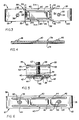
- Figure 3 is a top-elevational view of the ganging clip shown in Figures 1 and 2;
- Figure 4 is a cross-sectional view of the ganging clip taken along lines 4-4 of Figure 3;
- Figure 5 is a cross sectional-view of the ganging clip taken along lines 5-5 of Figure 3; and
- Figure 6 is a bottom view of the ganging clip shown in Figures 1 through 5.
- Referring to the drawings in detail, there is shown a
ganging clip 10 mounted to a pair of neighboring worksurface support brackets 12 to joinwork surfaces 14 secured thereto in load transmitting relationship and to adjust the relative heights of the work surfaces to thus position the same in substantially the same horizontal plane. - As shown in Figures 1 and 2, a pair of
work surfaces 14 are supported by a pair ofsupport brackets 12 securely mounted to a wall. The worksurface support brackets 12 utilized in connection with the invention are of the type mountable to vertical slottedstandards 16 securely attached to awall 18, or other similar support surface. To this end, eachsupport bracket 12 includes a horizontally disposed worksurface support arm 20 and avertical arm 22 having on theinner end 24 thereof a plurality of rearwardly and downwardly dependinghooks 26 removably received withinslots 28 of thevertical standard 16. In addition, the worksurface support arm 20 of thesupport bracket 12 is U-shaped, in cross section, and has an upperhorizontal leg 30, 30' a lowerhorizontal leg 32, 32' and avertical leg 34, 34' connected to and between upper and lower horizontal legs. Thework surface 14 is rigidly secured to the upperhorizontal leg 30, 30' of thesupport bracket 12. - The
ganging clip 10 is adapted to mount to a pair of neighboring worksurface support brackets 12. As illustrated in Figure 2, when mounted to thewall 18, thevertical legs 34, 34' of thesupport brackets 12 are juxtaposed in side by side and spaced-apart relationship and the upper and lower horizontal legs, 30, 30' and 32, 32' are positioned in opposite directions and in substantially the same horizontal planes. Specifically, theganging clip 10 is adapted to mount to the opposed lowerhorizontal legs 32, 32' of the neighboringsupport brackets 12. - The
ganging clip 10 comprises an enlongated rectangular plate having acentral web portion 36 and a pair ofidentical end portions 38. Theweb portion 36 includes a pair of locatingnotches 40 formed integral withlongitudinal sides 42 of the web and aligned along a central transverse axis of the same. In addition, theweb portion 36 has a pair ofstiffening ribs 44 formed integral with and positioned along longitudinal axes of the web. Further, a pair offulcrums 46 are formed integral with the web portion on opposite sides of the locatingnotches 40. It is contemplated that thenotches 40,stiffening ribs 44 andfulcrums 46 can be rigidly secured tocentral web portion 36. A pair ofopenings 48 extend through theweb portion 36 on opposite sides of the central transverse axis of the same. The functions of thefulcrums 46 and theribs 44 will be hereinafter explained in more detail when describing the operation of the gangingclip 10. - Each
end portion 38 includes a threadedhole 50 extending therethrough. Theend portions 38 are bent backwardly and positioned in overlapping relationship with respect to thecentral web portion 36 such that holes 50 of theweb portion 36 are aligned withopenings 48 of the end portions. In this manner,end portions 38 and theweb portion 36 form a pair of opposingresilient jaws 52. In addition, thecorners 53 of the free ends 54 of theend portions 38 are bent downwardly to form a pair ofteeth 55 on eachjaw 52. A pair ofscrews 56 havingthreads 57 are adapted to extend through theopenings 48 and threadably engage theholes 50. Torquing thescrews 56 results in the drawing together of theend portions 38 and theweb portion 36 and thus the closing of thejaws 52. In the same manner, loosening of thescrews 56 results in opening of thejaws 52. - For convenience in understanding the operation in the
ganging clip 10, the clip will hereinafter be referred to as having afirst side 58 and asecond side 60. To mount theganging clip 10 to the neighboringsupport brackets 12, thejaws 52 are set in registry with the lowerhorizontal legs 32, 32' of thesupport brackets 12 such that the locatingnotches 40 of theweb portion 36 are centered with respect to the neighboring support brackets and the lower legs of the support brackets rest on thefulcrums 46 of the web. Subsequently, theadjacent support brackets 12 and the work surfaces 14 secured thereto are manually adjusted laterally so as to makegap 62 between them substantially uniform along the full length of thehorizontal support arms 20 of the support brackets. Thescrews 56 are then tightened to clamp the lowerhorizontal legs 32, 32' of the gangingclip 10 between the web and end portions, 36 and 38, of the clip and to secure the above-described uniform spacing between the work surfaces 14. The disposition of the gangingclip 10 mounted on thesupport brackets 12 as just described is best illustrated in Figure 2. The clamping action of thejaws 52 causes theteeth 55 of the same to securely bite into the lowerhorizontal legs 32, 32' of thesupport brackets 12 to thereby securely join the neighboring work surfaces 14 in load transmitting relationship. In this manner, the gangingclip 10 functions as a load equalizer so that if a force is exerted on onework surface 14 it will not move relative to the other. Rather, both work surfaces will move as a single unit. - The relative heights of the work surfaces 14 can be subsequently adjusted by further tightening or loosening of either of the
screws 56. For example, further torquing ofscrew 56 of thefirst side 58 of theclip 10, results in downward movement of the web portion of thesecond side 60 of the clip. As thesecond side 60 moves downwardly, its corresponding work surface also moves downwardly with respect to the adjacent work surface. In the same manner, loosening ofscrews 56 of thefirst side 58 causes thework surface 14 associated with thesecond side 60 of theclip 10 to move upwardly relative to its neighboring work surface. Similarly, tightening and loosening ofscrew 56 of thesecond side 60 causes thework surface 14 associated with thefirst side 58 of the clip to move downwardly and upwardly, respectively, relative to the work surface associated with the second side. Manipulation of thescrews 56 as described above allows workers to vertically adjust the neighboring work surfaces 14 so as to position the same in substantially the same horizontal plane. - The
fulcrums 46 and the stiffeningribs 44 play an important role in the above-described adjustment feature of the gangingclip 10. When the gangingclip 10 is securely mounted to the neighboringsupport brackets 12, the lowerhorizontal legs 32, 32' of the brackets securely engage on thefulcrums 46. In addition, when, for example, thescrew 56 of thefirst side 58 of theclip 10 is tightened theweb portion 36 of the first side bends to assume a concave shape and pivots about itsrespective fulcrum 46. This causes theweb portion 36 of thesecond side 60 to deflect downwardly and the lowerhorizontal leg 32 of the support bracket associated with the second side to pivot laterally on itsrespective fulcrum 46 to thereby lower the support bracket, and the work surface attached thereto, relative to the support bracket of the first side of the clip. - The stiffening
ribs 44 function to add rigidity to thecentral web portion 36 of theclip 10, along longitudinal axes thereof. By adding rigidity to theclip 10, theribs 44 limit the amount of deflection of theweb portion 36 when either of thescrews 56 are tightened, as a result of adjustment of the relative heights of the work surfaces, to thereby prevent permanent deflection of theweb portion 36 subsequent to bending. Thus, for example, upon loosening of thescrew 56 of thefirst side 58, thesecond side 60 of theclip 10 resiliently responds and deflects upwardly to raise itscorresponding work surface 14 relative to the neighboring work surface. - In addition, since deflection of the
web portion 36 is limited, the web is better able to transmit force, from either end of theclip 10 to the other, generated when either of thescrews 56 are tightened. Thus, for example, whenscrew 56 of thefirst side 58 is tightened and theweb portion 36 of thesecond side 60 bends downwardly, the force necessary to lower thework surface 14 of the second side is transmitted from the first side to the second side of the clip. The stiffeningribs 44, by limiting the amount of deflection of thesecond side 60 of theclip 10, enable the central portion to optimally transfer the forces required to lower thework surface 14 of the second side relative to the first side. - In the preferred embodiment, the ganging
clip 10 is constructed of a spring temper steel so that the clip will not yield when portions of the same are deflected in operation. For example, the gangingclip 10 may be constructed of a heat-treated spring steel having a thickness of approximately 1,44 to 1,61 mm (.0568 to .0635 inches); SAE 1050 and 1075 steel; and a hardness of R35 (Rockwell) to R42 (Rockwell). Alternatively, theclip 10 can be made out of a high-strength low alloy steel. - While the invention will be described in connection with a preferred embodiment, it will be understood that we do not intend to limit the invention to that embodiment. To the contrary, we intend to cover all alternatives, modifications and equivalents as may be included within the scope of the invention as defined by the appended claims.
Claims (14)
- A ganging clip for mounting to first and second support brackets (12) which carry respectively work surfaces (14), wherein said first and second support brackets (12) are mounted to a wall (18) in side-by-side relationship and have opposed first and second substantially horizontal legs (32, 32'), said ganging clip (10) is adapted to be mounted to said first and said second horizontal legs (32, 32') to secure said first and second work surfaces (14) together in aligned, load-transmitting relationship,
characterized by
first and second jaws (58, 60) joined by a central web (36), the jaws (58, 60) adapted to securely clamp respectively to the first and second horizontal legs (32, 32');
a fastener (56) in said second jaw (60) for adjusting the position of an end portion (38) thereof with respect to said central web (36); and
a fulcrum (46) on said central web (36) adapted to contact said second horizontal leg (32) and positioned to vertically adjust the height of said second jaw (60) relative to said first jaw (58) to adjust the relative heights of said first and second work surfaces (14) when said fastener (56) is adjusted in said second jaw (60) and said jaws (58, 60) are secured respectively to said first and second horizontal legs (32, 32'). - The ganging clip of claim 1 wherein the fastener (56) is threaded into said end portion (38) of said second jaw (60).
- The ganging clip of claims 1 or 2 and further characterized in that said first jaw (58) has a second fastener (56) for adjusting the position of an end portion (38) thereof with respect to the central web (36).
- The ganging clip of claim 3 wherein said second fastener (56) is threaded into the end portion (38) of said first jaw (58).
- The ganging clip of claims 3 or 4 and further characterized in a second fulcrum (46) on the central web (36) and adapted to support said first horizontal leg (32') and positioned to vertically adjust the height of the first jaw (58) relative to the second jaw (60) to adjust the relative heights of the first and second support brackets (12) when the fastener (56) on the first jaw (58) is adjusted in said first jaw (58).
- The ganging clip of claim 5 wherein said second fulcrum (46) comprises a second embossment (46) formed integral with and extending along a substantially transverse axis of said central web (36).
- The ganging clip of claims 1 through 6 and further characterized in that said second jaw (60) is resilient.
- The ganging clip of claims 1 through 7 and further characterized in that said first jaw (58) is resilient.
- The ganging clip of claims 1 through 8 and further characterized in that said central web (36) has a stiffening means (44) for rigidifying the central web (36) to resist deflection of one portion of said central web (36) with respect to another.
- The ganging clip of claim 9 characterized in that said stiffening means (44) comprises at least one stiffening rib (44) formed integral with or rigidly secured to and extending along substantially longitudinal axes of said central web (36).
- The ganging clip of claims 1 through 10 characterized by a locating means (40) for centering said ganging clip (10) with respect to said first and second support brackets (12) when mounting said ganging clip (10) to said support brackets (12).
- The ganging clip of claim 11 characterized in that said locating means (40) comprises at least one locating notch (40) on said central web (36).
- The ganging clip of claims 1 through 12 characterized in that the first fulcrum (46) comprises a first embossment (46) formed integral with and extending along a substantially transverse axis of said central web (36).
- The ganging clip of claims 1 through 13 characterized in that said first and second jaws (58, 60) have end portions (38) with downwardly depending bent corners (53) adapted to engage said first and second horizontal legs (32, 32') when said jaws (58, 60) are secured to said first and second horizontal legs (32, 32').
Applications Claiming Priority (2)
| Application Number | Priority Date | Filing Date | Title |
|---|---|---|---|
| US86009586A | 1986-05-06 | 1986-05-06 | |
| US860095 | 1986-05-06 |
Publications (2)
| Publication Number | Publication Date |
|---|---|
| EP0244505A1 EP0244505A1 (en) | 1987-11-11 |
| EP0244505B1 true EP0244505B1 (en) | 1992-07-29 |
Family
ID=25332483
Family Applications (1)
| Application Number | Title | Priority Date | Filing Date |
|---|---|---|---|
| EP86113476A Expired - Lifetime EP0244505B1 (en) | 1986-05-06 | 1986-10-01 | Work surface ganging clip |
Country Status (4)
| Country | Link |
|---|---|
| US (1) | US4802422A (en) |
| EP (1) | EP0244505B1 (en) |
| CA (1) | CA1258257A (en) |
| DE (2) | DE3686261T4 (en) |
Families Citing this family (16)
| Publication number | Priority date | Publication date | Assignee | Title |
|---|---|---|---|---|
| US5290156A (en) * | 1991-07-29 | 1994-03-01 | Mayland Harold E | Walking beam compressor assembly |
| US5259691A (en) * | 1991-09-04 | 1993-11-09 | The Swan Corporation | Countertop clamping apparatus and method of using same |
| US5259165A (en) * | 1992-08-10 | 1993-11-09 | Tomoe Kogyo Kabushiki Kaisha | Supporting metal fittings for double beams |
| CA2136574C (en) * | 1993-12-03 | 1999-11-16 | John Kemp | Trader desk frame |
| JPH08121427A (en) * | 1994-10-25 | 1996-05-14 | Delta Tsuuring:Kk | Connecting device for plate-shaped members |
| US5678948A (en) * | 1995-12-07 | 1997-10-21 | B. Walter And Co., Inc. | Selectively lockable and horizontally and vertically aligning latch for furniture parts |
| US5595427A (en) * | 1996-02-13 | 1997-01-21 | Transfer Flow International, Inc. | Modular countertop |
| US5852904A (en) * | 1996-08-05 | 1998-12-29 | Haworth, Inc. | Panel arrangement |
| US6711871B2 (en) | 2000-05-03 | 2004-03-30 | Herman Miller, Inc. | Wall panel with off-module components |
| US6485219B1 (en) | 2000-11-20 | 2002-11-26 | Haworth, Inc. | Ganging bracket for a shelf unit |
| US20040052580A1 (en) * | 2002-09-18 | 2004-03-18 | Lawson Alan Douglas | Connection clip for boltless storage units and work benches with concealed holes angle post |
| DE102005000121A1 (en) * | 2005-09-21 | 2007-03-22 | Hilti Ag | Holding element for grille has hole for screw through first arm, and counter-thread in second arm to take screw |
| US7806474B2 (en) * | 2009-01-14 | 2010-10-05 | Kimball International, Inc. | Connecting arrangement for articles of furniture |
| US9052120B2 (en) * | 2012-09-14 | 2015-06-09 | Miami Tech, Inc. | Equipment stand |
| US10045609B1 (en) * | 2015-09-18 | 2018-08-14 | Eric Insua | Divisible and collapsible table having mounting means |
| US12031563B1 (en) * | 2017-11-02 | 2024-07-09 | Steven Andrew Roth | Clamp and method of clamping to metal decking |
Family Cites Families (11)
| Publication number | Priority date | Publication date | Assignee | Title |
|---|---|---|---|---|
| US893378A (en) * | 1907-10-10 | 1908-07-14 | Mortimer C Rosenfeld | Adjustable beam-clamp. |
| US1203752A (en) * | 1915-10-22 | 1916-11-07 | Eugene J Le Claire | Supplemental table-top. |
| AT86663B (en) * | 1920-01-10 | 1921-12-10 | Johann Futterknecht | Device for the fixed association of tables set up side by side u. like |
| US1976595A (en) * | 1933-04-27 | 1934-10-09 | Hans J Asleson | Hanger |
| US2609582A (en) * | 1949-08-01 | 1952-09-09 | Kindorf Co | Adjustable beam clamp |
| US2848289A (en) * | 1957-05-23 | 1958-08-19 | Shaw Walker Co | Furniture clamping device |
| US3015897A (en) * | 1960-04-14 | 1962-01-09 | Hopp Press Inc | Display device |
| US3130693A (en) * | 1962-03-14 | 1964-04-28 | Irving W Shell | Bracket support structure |
| US3276800A (en) * | 1963-05-07 | 1966-10-04 | Minerallac Electric Company | Beam clip |
| US3267881A (en) * | 1964-07-06 | 1966-08-23 | Johanna M Saggione | Beautician's module and method of making same |
| US4409906A (en) * | 1981-03-31 | 1983-10-18 | Alneng Carl Goeran | Clamping device for joining boards |
-
1986
- 1986-08-28 CA CA000517070A patent/CA1258257A/en not_active Expired
- 1986-10-01 DE DE3686261T patent/DE3686261T4/en not_active Expired - Lifetime
- 1986-10-01 DE DE8686113476A patent/DE3686261D1/en not_active Expired - Lifetime
- 1986-10-01 EP EP86113476A patent/EP0244505B1/en not_active Expired - Lifetime
-
1987
- 1987-09-15 US US07/096,665 patent/US4802422A/en not_active Expired - Lifetime
Also Published As
| Publication number | Publication date |
|---|---|
| DE3686261T4 (en) | 1995-08-10 |
| DE3686261T2 (en) | 1993-02-04 |
| DE3686261D1 (en) | 1992-09-03 |
| US4802422A (en) | 1989-02-07 |
| CA1258257A (en) | 1989-08-08 |
| EP0244505A1 (en) | 1987-11-11 |
Similar Documents
| Publication | Publication Date | Title |
|---|---|---|
| US4802422A (en) | Work surface ganging clip | |
| US4582001A (en) | Shelf connector assembly | |
| US6019331A (en) | Cantilever bracket assembly | |
| US5733097A (en) | Cross-bar tool mounting system | |
| US6070957A (en) | Device for fastening a support rail on frame legs and mounting panels of a switchgear cabinet | |
| US6978906B2 (en) | Modular rack conversion apparatus and method | |
| US4923322A (en) | Clamped framework assembly and connectors used therewith | |
| US5645257A (en) | Adjustable support apparatus | |
| US7954776B2 (en) | Wire basket pathway system | |
| US4928914A (en) | Tiltable mounting bracket | |
| US20040001739A1 (en) | Connecting Part for Mounting Rails | |
| US6315137B1 (en) | Structural channel connector and method of manufacture | |
| CA1189834A (en) | Load support arrangement | |
| EP1164336A1 (en) | Duct lifting lug and method of suspending duct using the lifting lug | |
| US3554477A (en) | Cantilever storage rack | |
| US5707170A (en) | Connector for agricultural tubes and toolbars | |
| US4880204A (en) | Load transmitting device | |
| MXPA97005977A (en) | Connector for agricultural tools and tubes | |
| JPH078336A (en) | Column and horizontal member used for rack assembly | |
| JP2965975B2 (en) | Device for combining side-by-side switch cabinets | |
| GB2148100A (en) | Stayed framework arrangement, for example for a shelf system | |
| US4050753A (en) | Braceable rail | |
| SK75393A3 (en) | Connecting element for connecting construction units | |
| JPS5922520A (en) | Platform equipped with card guide movable by side slide guide | |
| JPH0582327U (en) | Double-column assembled steel shelf top shelf shelf |
Legal Events
| Date | Code | Title | Description |
|---|---|---|---|
| PUAI | Public reference made under article 153(3) epc to a published international application that has entered the european phase |
Free format text: ORIGINAL CODE: 0009012 |
|
| AK | Designated contracting states |
Kind code of ref document: A1 Designated state(s): AT BE CH DE ES FR GB GR IT LI LU NL SE |
|
| RBV | Designated contracting states (corrected) |
Designated state(s): DE FR GB |
|
| 17P | Request for examination filed |
Effective date: 19880509 |
|
| 17Q | First examination report despatched |
Effective date: 19890927 |
|
| GRAA | (expected) grant |
Free format text: ORIGINAL CODE: 0009210 |
|
| AK | Designated contracting states |
Kind code of ref document: B1 Designated state(s): DE FR GB |
|
| REF | Corresponds to: |
Ref document number: 3686261 Country of ref document: DE Date of ref document: 19920903 |
|
| ET | Fr: translation filed | ||
| PLBE | No opposition filed within time limit |
Free format text: ORIGINAL CODE: 0009261 |
|
| STAA | Information on the status of an ep patent application or granted ep patent |
Free format text: STATUS: NO OPPOSITION FILED WITHIN TIME LIMIT |
|
| 26N | No opposition filed | ||
| PGFP | Annual fee paid to national office [announced via postgrant information from national office to epo] |
Ref country code: FR Payment date: 20000828 Year of fee payment: 15 |
|
| PGFP | Annual fee paid to national office [announced via postgrant information from national office to epo] |
Ref country code: GB Payment date: 20000921 Year of fee payment: 15 |
|
| PGFP | Annual fee paid to national office [announced via postgrant information from national office to epo] |
Ref country code: DE Payment date: 20001130 Year of fee payment: 15 |
|
| PG25 | Lapsed in a contracting state [announced via postgrant information from national office to epo] |
Ref country code: GB Free format text: LAPSE BECAUSE OF NON-PAYMENT OF DUE FEES Effective date: 20011001 |
|
| REG | Reference to a national code |
Ref country code: GB Ref legal event code: IF02 |
|
| GBPC | Gb: european patent ceased through non-payment of renewal fee |
Effective date: 20011001 |
|
| PG25 | Lapsed in a contracting state [announced via postgrant information from national office to epo] |
Ref country code: FR Free format text: LAPSE BECAUSE OF NON-PAYMENT OF DUE FEES Effective date: 20020628 |
|
| PG25 | Lapsed in a contracting state [announced via postgrant information from national office to epo] |
Ref country code: DE Free format text: LAPSE BECAUSE OF NON-PAYMENT OF DUE FEES Effective date: 20020702 |
|
| REG | Reference to a national code |
Ref country code: FR Ref legal event code: ST |