EP0244079A2 - Procédé et appareil por contrôler la composition d'un mélange quittant un évaporateur - Google Patents
Procédé et appareil por contrôler la composition d'un mélange quittant un évaporateur Download PDFInfo
- Publication number
- EP0244079A2 EP0244079A2 EP87302521A EP87302521A EP0244079A2 EP 0244079 A2 EP0244079 A2 EP 0244079A2 EP 87302521 A EP87302521 A EP 87302521A EP 87302521 A EP87302521 A EP 87302521A EP 0244079 A2 EP0244079 A2 EP 0244079A2
- Authority
- EP
- European Patent Office
- Prior art keywords
- liquid mixture
- temperature
- estimated
- component
- evaporator
- Prior art date
- Legal status (The legal status is an assumption and is not a legal conclusion. Google has not performed a legal analysis and makes no representation as to the accuracy of the status listed.)
- Granted
Links
- 239000000203 mixture Substances 0.000 title claims abstract description 170
- 238000000034 method Methods 0.000 title claims description 64
- 230000008569 process Effects 0.000 title claims description 48
- 239000007788 liquid Substances 0.000 claims abstract description 119
- 238000009835 boiling Methods 0.000 claims abstract description 61
- 239000000306 component Substances 0.000 claims description 83
- 239000000543 intermediate Substances 0.000 claims description 71
- 235000000346 sugar Nutrition 0.000 claims description 49
- 230000000694 effects Effects 0.000 claims description 35
- 238000010438 heat treatment Methods 0.000 claims description 35
- 230000008016 vaporization Effects 0.000 claims description 34
- 239000007787 solid Substances 0.000 claims description 26
- XLYOFNOQVPJJNP-UHFFFAOYSA-N water Substances O XLYOFNOQVPJJNP-UHFFFAOYSA-N 0.000 claims description 24
- 230000001276 controlling effect Effects 0.000 claims description 18
- 239000000463 material Substances 0.000 claims description 18
- 238000004364 calculation method Methods 0.000 claims description 17
- 235000020357 syrup Nutrition 0.000 claims description 12
- 239000006188 syrup Substances 0.000 claims description 12
- 235000005824 Zea mays ssp. parviglumis Nutrition 0.000 claims description 11
- 235000002017 Zea mays subsp mays Nutrition 0.000 claims description 11
- 235000005822 corn Nutrition 0.000 claims description 11
- 239000012530 fluid Substances 0.000 claims description 11
- 238000004519 manufacturing process Methods 0.000 claims description 10
- 230000004044 response Effects 0.000 claims description 10
- 229930006000 Sucrose Natural products 0.000 claims description 9
- CZMRCDWAGMRECN-UGDNZRGBSA-N Sucrose Chemical compound O[C@H]1[C@H](O)[C@@H](CO)O[C@@]1(CO)O[C@@H]1[C@H](O)[C@@H](O)[C@H](O)[C@@H](CO)O1 CZMRCDWAGMRECN-UGDNZRGBSA-N 0.000 claims description 9
- 239000005720 sucrose Substances 0.000 claims description 9
- 238000001704 evaporation Methods 0.000 claims description 8
- 230000008020 evaporation Effects 0.000 claims description 7
- 230000000875 corresponding effect Effects 0.000 claims 3
- 241000209149 Zea Species 0.000 claims 2
- 239000012467 final product Substances 0.000 abstract description 3
- 239000000243 solution Substances 0.000 description 41
- 239000000047 product Substances 0.000 description 22
- 238000005336 cracking Methods 0.000 description 12
- 238000006243 chemical reaction Methods 0.000 description 11
- 240000008042 Zea mays Species 0.000 description 9
- 238000002425 crystallisation Methods 0.000 description 9
- 230000008859 change Effects 0.000 description 7
- 230000008025 crystallization Effects 0.000 description 7
- 150000008163 sugars Chemical class 0.000 description 7
- 230000009471 action Effects 0.000 description 6
- 238000004458 analytical method Methods 0.000 description 6
- 239000013078 crystal Substances 0.000 description 5
- 238000005259 measurement Methods 0.000 description 5
- 235000019219 chocolate Nutrition 0.000 description 4
- 229920006395 saturated elastomer Polymers 0.000 description 4
- 241000227653 Lycopersicon Species 0.000 description 3
- 235000007688 Lycopersicon esculentum Nutrition 0.000 description 3
- 239000012141 concentrate Substances 0.000 description 3
- 235000009508 confectionery Nutrition 0.000 description 3
- 239000003085 diluting agent Substances 0.000 description 3
- 239000012527 feed solution Substances 0.000 description 3
- 239000011874 heated mixture Substances 0.000 description 3
- 238000010025 steaming Methods 0.000 description 3
- 241000196324 Embryophyta Species 0.000 description 2
- 239000007864 aqueous solution Substances 0.000 description 2
- 238000004422 calculation algorithm Methods 0.000 description 2
- 235000008504 concentrate Nutrition 0.000 description 2
- 238000010924 continuous production Methods 0.000 description 2
- 230000001419 dependent effect Effects 0.000 description 2
- 238000006073 displacement reaction Methods 0.000 description 2
- 235000013305 food Nutrition 0.000 description 2
- 239000012456 homogeneous solution Substances 0.000 description 2
- VNWKTOKETHGBQD-UHFFFAOYSA-N methane Chemical compound C VNWKTOKETHGBQD-UHFFFAOYSA-N 0.000 description 2
- 238000002156 mixing Methods 0.000 description 2
- 239000002244 precipitate Substances 0.000 description 2
- 235000020374 simple syrup Nutrition 0.000 description 2
- 239000002002 slurry Substances 0.000 description 2
- 238000009834 vaporization Methods 0.000 description 2
- 238000005303 weighing Methods 0.000 description 2
- 238000012935 Averaging Methods 0.000 description 1
- 206010052804 Drug tolerance Diseases 0.000 description 1
- UFHFLCQGNIYNRP-UHFFFAOYSA-N Hydrogen Chemical compound [H][H] UFHFLCQGNIYNRP-UHFFFAOYSA-N 0.000 description 1
- 229920002472 Starch Polymers 0.000 description 1
- 238000012993 chemical processing Methods 0.000 description 1
- 238000001816 cooling Methods 0.000 description 1
- 238000012937 correction Methods 0.000 description 1
- 230000001934 delay Effects 0.000 description 1
- 238000010586 diagram Methods 0.000 description 1
- 235000015203 fruit juice Nutrition 0.000 description 1
- 239000000446 fuel Substances 0.000 description 1
- 239000008240 homogeneous mixture Substances 0.000 description 1
- 229910052739 hydrogen Inorganic materials 0.000 description 1
- 239000001257 hydrogen Substances 0.000 description 1
- 239000012770 industrial material Substances 0.000 description 1
- 230000000977 initiatory effect Effects 0.000 description 1
- 239000007791 liquid phase Substances 0.000 description 1
- 238000012067 mathematical method Methods 0.000 description 1
- 238000012986 modification Methods 0.000 description 1
- 230000004048 modification Effects 0.000 description 1
- 235000013379 molasses Nutrition 0.000 description 1
- 238000012544 monitoring process Methods 0.000 description 1
- 229930014626 natural product Natural products 0.000 description 1
- 230000010355 oscillation Effects 0.000 description 1
- 230000000704 physical effect Effects 0.000 description 1
- 238000013404 process transfer Methods 0.000 description 1
- 238000012545 processing Methods 0.000 description 1
- 239000012266 salt solution Substances 0.000 description 1
- 239000007790 solid phase Substances 0.000 description 1
- 239000002195 soluble material Substances 0.000 description 1
- 239000007921 spray Substances 0.000 description 1
- 235000019698 starch Nutrition 0.000 description 1
- 239000008107 starch Substances 0.000 description 1
- -1 steam Substances 0.000 description 1
- 239000000126 substance Substances 0.000 description 1
- 238000012546 transfer Methods 0.000 description 1
- 230000000007 visual effect Effects 0.000 description 1
Images

Classifications
-
- C—CHEMISTRY; METALLURGY
- C13—SUGAR INDUSTRY
- C13B—PRODUCTION OF SUCROSE; APPARATUS SPECIALLY ADAPTED THEREFOR
- C13B30/00—Crystallisation; Crystallising apparatus; Separating crystals from mother liquors ; Evaporating or boiling sugar juice
- C13B30/02—Crystallisation; Crystallising apparatus
- C13B30/022—Continuous processes, apparatus therefor
- C13B30/025—Continuous processes, apparatus therefor combined with measuring instruments for effecting control of the process
-
- B—PERFORMING OPERATIONS; TRANSPORTING
- B01—PHYSICAL OR CHEMICAL PROCESSES OR APPARATUS IN GENERAL
- B01D—SEPARATION
- B01D1/00—Evaporating
- B01D1/0082—Regulation; Control
-
- B—PERFORMING OPERATIONS; TRANSPORTING
- B01—PHYSICAL OR CHEMICAL PROCESSES OR APPARATUS IN GENERAL
- B01D—SEPARATION
- B01D1/00—Evaporating
- B01D1/26—Multiple-effect evaporating
Definitions
- This invention relates to a process and apparatus for controlling the composition of a mixture leaving an evaporator.
- an evaporator is used to adjust the relative proportions of the two components in a mixture comprising a first, relatively non-volatile component and a second component which is more volatile than the first component.
- the exact chemical and physical properties of the two components are not critical provided a significant difference in volatility is present.
- the first component may comprise a substantially non-volatile solid, such as a sugar, and the second component comprise water.
- the first component may be a relatively non-volatile liquid and the second component a more volatile liquid.
- Such evaporators are frequently of the multi-stage type, in which a feed stream of the mixture is supplied to a first stage, in which it is heated and part of the second component distilled off. The mixture is reheated, and additional first component distilled off, to produce a mixture which is further enriched in the first component. Third, fourth, etc. stages may be added if necessary.
- the concentration of the final solution emerging from such a multi-stage evaporator is affected by a large number of variables, including many of the typical variables inherent in any complicated chemical processing plant, for example, slight variations in the rate of supply of heat to the solutions in the various stages of the evaporator caused by variations in the rate of flow of the heat transfer medium used, usually steam, variations in the rate at which mechanical pumps pump the solution to the evaporator, etc.
- the feed solution is usually made up by weighing and mixing a number of components, the concentration of the final solution is also subject to weighing errors.
- sugars are natural products, variations may occur in the sugar products themselves, for example, in the concentration of sugar in the form of a corn syrup or other sugar syrup.
- multi-stage evaporators have been controlled by a feedback system in which the final solution has been analyzed to determine the proportions of the components therein, and the analytical results used to control the heat input to the evaporator, for example by controlling the supply of steam thereto.
- densiometers and refractometers do produce substantially instantaneous analytical results, thereby avoiding the problems of delay experienced with manual analysis, with highly concentrated solutions of sugars and other highly soluble materials the accuracy of the analytical results produced by densiometers and refractometers is too low to provide sufficiently precise control to meet the close tolerances of product specification required in many industrial processes.
- control of a multi-stage evaporator is similar in many respects to control of other continuous processes used in many industrial material processing applications, and a wide variety of methods for controlling such continuous processes are known. For example, various methods have been proposed for controlling the degree of crystallization during the evaporation of sugar solutions.
- U.S. Patent No. 4,056,364 to Dmitrovsky et al. describes a two-stage crystallization process for crystallization of various solutes, primarily sugars.
- a solution of the solute is introduced into a first stage evaporative-crystallization zone together with seed solute crystals, the solution is concentrated to yield a saturated first stage concentrate containing crystals of the solute, which are substantially larger than the seed crystals and are suspended in a solution more concentrated with respect to the solute than the solution fed to the first stage zone.
- a stream of the first stage concentrate is removed from the first stage zone and transferred to a second evaporative-crystallization zone for further concentration or crystallization of solute and the production of solute crytals of increased size.
- U.S. Patent No. 4,196,385 to Vestergaard et al. describes a method and apparatus for measuring the concentration of a solid/liquid mixture, especially sugar crystals in a syrup.
- the concentration measuring method relies upon the variation of dielectric constant of the fluid with the relative proportions of solid and liquid. Electric oscillations are supplied from a source through an impedance matching link to an antenna placed in the liquid within the confines of a Faraday cage, and the electric power reflected from the antenna towards the source is measured to determine deviations from ideal matching resulting from changes in the dielectric constant of the fluid, resulting from changes in the proportion of solid therein.
- Column 1, lines 37-47 of the patent discusses methods for control of the concentration of a solution by measuring increases in its boiling point and points out that this method is not suitable for the final crystallization stages.
- U.S. Patent No. 4,231,753 to Stewart describes a process for the control of a cracking furnace in which the heat supplied to the furnace is controlled in response to a calculation of the heat required to maintain a desired conversion rate for the material being cracked in the cracking furnace.
- the flow rates of the steam and feed material supplied to the cracking furnace are measured, and the feed material itself is analyzed to predict the heat required to maintain a desired conversion rate, then the fuel supply to the furnace is manipulated to provide the calculated heat requirement, thus providing a form of feed-forward control.
- the calculated heat requirement is corrected by a comparison of the actual conversion rate with the desired conversion rate.
- U.S. Patent No. 4,349,869 to Prett et al. describes a method for controlling and optimizing the operation of a series of interdependent processes in a plant environment.
- Manipulation of one or more con strained process input variables is used to achieve feedforward/feedback control of one or more process output variables.
- input variables are subjected to measured perturbations and the dynamic effects of these perturbations on the outputs are noted for prediction of future response of the processes during online operation.
- U.S. Patent No. 4,536,606 to Hobbs describes a process for manipulating the heat provided to a cracking furnace so as to maintain the actual conversion of a first component in the feed stream to the cracking furnace substantially equal to a desired conversion for this component.
- the actual conversion of the first component is determined by analyzing the concentration of the first component in the feed stream, analyzing the concentration of the first component in the product stream, estimating the conversion of the first component and calculating the expansion of the feed stream in the cracking furnace.
- the calculated actual conversion is compared to a desired conversion and used, together with the feed flow rate, to manipulate the heat provided to the cracking furnace. Again, in such a process there can be no measurement of a boiling point and use of this boiling point for feedforward control of a later stage of the process.
- U.S. Patent No. 4,257,105 to Stewart describes a process for controlling the flow rate of a diluent fluid, such as steam, hydrogen or methane, to a cracking furnace so as to maintain a desired outlet velocity for the effluent flowing from the cracking furnace or to maintain a desired residence time for the feed stream in the cracking furnace.
- Feedforward control for the flow rate of the diluent fluid is provided by using an empirical model of the cracking furnace to predict either the outlet velocity or the residence time based upon measured system parameters.
- Feedback control for the flow rate of the diluent fluid is provided by calculating the actual outlet velocity or actual residence time based on measured system parameters.
- the measured outlet velocity or residence time is utilized to bias or correct the predicted outlet velocity or residence time to provide a corrected prediction of the outlet velocity or residence time. Again, in such a process there can be no measurement of a boiling point and use of this boiling point for feedforward control of a later stage of the process.
- U.S. Patent No. 4,173,215 to Bureau et al. describes an apparatus for steaming food at substantially atmospheric conditions. Steam is generated in a steam/generating chamber 67 and passes to a steaming chamber 33 in which the food to be steamed is placed. Excess steam escapes by a vent 111 into a condensing chamber 121 provided with a spray nozzle 133 through which cold water is sprayed to condense the excess steam. A temperature sensor is provided within the chamber 121 to sense the temperature of the water and condensed steam in the condensing chamber, and the output from this temperature sensor is used to control the generation of steam in the apparatus.
- U.S.S.R. Patent No. 785,353 discloses an apparatus for the controlled steaming of starch-containing material in which the actual temperature of the mass being steamed is measured after the "secondary-heating contact head" and this measured temperature is used to regulate a valve controlling the steam supply.
- the steam flow-rate setting is determined by the measured temperature, the flow-rate of a water/grain mix and the actual and predetermined temperatures of the mass after the contact head.
- U.S. Patent No. 4,437,934 to Nelson et al. describes a process for manufacturing tomato products to a predetermined consistency standard.
- a tomato extract feedstock has its initial precipitate weight ratio and initial Brix level measured. From these measurements an expected precipitate weight ratio and an expected Brix level of the tomato product are calculated and the degree of concentration controlled to provide the predetermined consistency.
- U.S. Patent No. 4,519,304 to Ripani describes a device for controlling and monitoring the thickness of a chocolate film delivered by chocolate refiners.
- An indirect measurement of the instantaneous chocolate film thickness effected by a colorimetric technique is used to determined the instantaneous thickness, the colorimetric readout head being arranged to reciprocate across the entire width of the film.
- the readout head also checks the integrity of the chocolate film being delivered by detecting the appearance of dry band areas and can also stop the machine if such lack of integrity appears for a predetermined time.
- None of the prior art control methods discussed above provides a solution to the problem of controlling the operation of a multi-stage evaporator in a manner which will ensure production of a product having a predetermined composition within tight tolerances without the risk of producing substantial quantities of product failing to meet its specification because of delays in analyzing the product and using the results of such analysis to control the operation of the multi-stage evaporator.
- This invention provides such a process, and evaporators for use in the process.
- This invention provides a process for controlling the composition of a liquid mixture.
- This process comprises: effecting a first heating of a feed mixture, this feed mixture comprising a first component and a second component more volatile than the first component; permitting boiling of the heated feed mixture under a known pressure, thereby producing a first vapor and an intermediate liquid mixture; measuring the temperature at which this boiling occurs; calculating from the measured boiling temperature the proportions of the first and second components therein; effecting a second heating of the intermediate liquid mixture, and permitting boiling thereof, thereby producing a second vapor and a final liquid mixture; and controlling the heat input to the intermediate liquid mixture in response to the calculated proportions of the first and second components therein, thereby producing the final liquid mixture with substantially a predetermined composition.
- This invention also provides apparatus for the production of a liquid mixture having substantially a predetermined composition, this apparatus comprising: supply means for supplying a feed mixture comprising a first component and a second component more volatile than the first component; a first evaporator having an inlet arranged to receive the feed mixture from the supply means, an outlet for a first vapor and an outlet for an intermediate liquid mixture; first heating means for supplying heat to the first evaporator and thereby causing boiling of the second component from the feed mixture to produce the first vapor and the intermediate liquid mixture; a temperature sensor arranged to measure the temperature at which this boiling occurs; calculating means for calculating from the measured boiling temperature the proportions of the first and second components in the intermediate liquid mixture; a second evaporator having an inlet for receiving the intermediate liquid mixture from the first evaporator, an outlet for a second vapor and an outlet for a final liquid mixture; and variable second heating means for supplying heat to the second evaporator, and thereby causing boiling of the second component from the feed mixture to
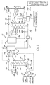
- Figure 1 shows a two-stage evaporator (generally designated 10) of the invention, this evaporator being used for concentrating a sugar solution used in the production of candy.
- the dilute sugar solution used as the feed mixture to the apparatus 10 is produced by feeding weighed batches of water, corn syrup, sucrose and molasses along lines 12, 14, 16 and 18 respectively to a mixer 20, where they are mixed to form a sugar solution.
- This sugar solution is fed by a line 22 to a positive displacement pump 24, which pumps the solution via a line 26 equipped with a flow sensor 28 to the feed solution inlet 30 of a first stage evaporator, generally designated 32.
- the mixture produced in the mixer 20 has been referred to as "a sugar solution", in practice this mixture may be either a homogeneous solution or a slurry of solid crystals in a solution, depending upon the concentration of sugar and the temperature at which the mixing is effected, which in practice is usually room temperature. Whether the mixture produced in the mixer 20 is a true solution or a slurry makes no difference to the process of the present invention provided that all the first component dissolves to produce a true solution before the boiling temperature is measured.
- the process of the present invention cannot be operated satisfactorily if any undissolved first component is present when the boiling temperature is measured, since under such circumstances the measured boiling temperature is that of the liquid phase alone, does not vary with the amount of the solid phase present, and thus does not accurately indicate the proportions of the first and second components in the intermediate liquid mixture.
- the first stage evaporator 32 comprises a heating section 34 and a vaporizing section 36.
- heating section 34 In practice vaporization occurs in both the heating section 34 and the vaporizing section 36. However, the terms “heating section” and “vaporizing section” are used for convenience since the heat input to the solution occurs in the heating section 34 while all the vapor is separated from the solution in the vaporizing section 36.
- the sugar solution passes from the feed mixture inlet 30 via a coil 38 to a mixture outlet 40.
- the coil 38 is disposed within a housing 42. Steam is fed under pressure into the housing 42 via a steam line 44 equipped with a variable flow controller 46 of conventional type. Steam condensate can escape from the housing 42 via a steam condensate outlet line 48.
- the heated mixture leaving the mixture outlet 40 of the heating section 34 passes via a line 50 to the vaporizing section 36.
- the vaporizing section 36 of the first evaporator 32 has an inlet 56 connected to the line 50 and through which the heated mixture enters the evaporator section, a vapor outlet 58 and an intermediate liquid mixture outlet 60.
- the feed mixture from the heating section 34 boils, thereby producing a first vapor stream (steam), which leaves the vaporizing section 36 via the vapor outlet 58, and an intermediate liquid mixture, which is more concentrated than the feed mixture, and which leaves the vaporizing section 36 via the outlet 60.
- the varorizing section 36 is equipped with a level controller 61 which regulates the operation of the pump 24.
- the line 50 is equipped with a temperature sensor 52 which senses the temperature of the heated stream passing along the line 50.
- An output signal from the temperature sensor 52 is sent to a temperature controller 53, which in turn sends a signal along a line 54 to the flow controller 46 and controls the operation of this flow controller, thereby controlling the flow of steam along the line 44 so as to ensure that the heated mixture passing along the line 50 is maintained at a predetermined temperature.
- the signal from the temperature sensor 52 is also passed, via the temperature controller 53, to a calculating and delay assembly 68.
- This calculating and delay assembly 68 is described in detail below.
- the temperature sensor 52 has been shown in the line 50 outside the vaporizing section 36, in practice it is advisable to place the temperature sensor 52 as close as possible to the outlet of the line 50, which in a commercial apparatus usually has a stub extending inside the housing of the vaporizing section 36. Thus, in practice the temperature sensor 52 will normally be disposed inside the housing of the vaporizing section 36, in the steam, and will thus accurately indicate the temperature at which boiling of the heated feed mixture occurs.
- the process of the present invention requires that the temperature at which the heated feed mixture boils be measured in order that this boiling temperature may be used to calculate the proportions of the first and second components in the intermediate liquid mixture produced by this boiling.
- this boiling temperature can be measured with sufficient accuracy, the exact location of the temperature sensor used to measure the boiling temperature is not critical.
- the relevant temperature sensor may be located in the line 50 by which the heated feed mixture is fed to the vaporizing section, within the vaporizing section itself, or in the line by which the intermediate liquid mixture passes from the vaporizing section of the first stage to the second stage of the evaporator.
- temperature sensed by the temperature sensor 52 is the same as the temperature of the boiling mixture within the vaporizing section 36.
- this boiling liquid mixture within the vaporizing section 36 is necessarily in equilibrium with the first vapor stream, which leaves the outlet 58 of the vaporizing section 36 under a known pressure, namely the pressure at which the vaporizing section 36 is allowed to operate.
- the pressure under which the vapor leaves the outlet 58 is usually atmospheric pressure in most industrial two-stage evaporators, although sub-atmospheric or even super-atmospheric pressure can be employed if so desired.
- the actual pressure of the vapor leaving the outlet 58 is not critical, providing this pressure is constant, since in the process of the invention it is necessary to know the pressure of water vapor with which the boiling mixture in the vaporizing section 36 is in equilibrium.
- the output from the temperature sensor 52 is fed to the calculating and delay assembly 68.
- the intermediate liquid mixture passes from the outlet 60 along a line 62 to the inlet of a positive displacement pump 64.
- the line 62 is provided with a temperature sensor 66, which senses the temperature of the intermediate liquid mixture passing along the line 62. The temperature sensed by the temperature sensor 66 is used in the heat balance calculations for the second stage of the evaporator, as described in more detail below.
- the sensor 52 which is used to measure the boiling temperature of the heated liquid mixture, may be located in the line by which the intermediate liquid mixture is fed to the second stage of the evaporator, i.e., in the line 62.
- the temperature sensors 52 and 66 may be replaced by a single temperature sensor located in the line 62, and the outp'ut from this temperature sensor used both for determining the boiling temperature of the heated liquid mixture and for the heat balance calculations relating to the second stage of the evaporator.
- significent heat loss takes place along the length of the line 62 (which is usually of considerable length), so that it is preferred to use two separate temperature sensors as shown in Figure 1.
- the sensor 66 should be located as close as practicable to the inlet to the second stage of the evaporator in order that the temperature sensed may accurately reflect the temperature at which the intermediate liquid mixture enters the second stage of the evaporator.
- the distance between the temperature sensor 66 and the second stage of the evaporator is exaggerated in Figure 1 relative to the length of the line 62 for ease of illustration.
- the pump 64 pumps the intermediate liquid mixture through a line 70 to the intermediate liquid inlet 72 of a second stage evaporator 74.
- This second stage evaporator 74 comprises a heating section 76 and a vaporizing section 78, both of which are identical to the corresponding sections 34 and 36 respectively of the first stage evaporator 32.
- the second stage evaporator 74 further comprises a vacuum section 80.
- the line 70 which feeds the intermediate liquid mixture to the inlet 72 of the second stage evaporator 74 is provided with a flow sensor 82 which measures the rate of flow of the intermediate liquid mixture along the line 70 and sends a signal representative of this rate of flow to the calculating and delay assembly 68.
- the heating section 76 of the second stage evaporator 74 has a coil 84, a heated liquid outlet 86, a housing 88, a line 90 for supplying steam to the housing 88, and a steam condensate outlet line 92, all are which identical to the corresponding parts of the heating section 34 of the first stage evaporator 32.
- the line 90 is provided with an flow controller 94 to control the flow of steam therealong, but this flow controller 94 is controlled by the calculating and delay assembly 68.
- the heated intermediate mixture leaving the outlet 86 of the heating section 76 passes to the vaporizing section 78 along a line 96, which is equipped with a temperature sensor 98.
- This temperature sensor 98 supplies a signal representative of the temperature of the heated liquid passing along the line 96 to a temperature controller 99, which in turn sends a temperature signal to the calculating and delay assembly 68.
- the vaporizing section 78 of the second stage evaporator 74 has an inlet 100 connected to the line 96, a vapor outlet 102 and a final liquid mixture outlet 104, all of which correspond to the inlet 56 and the outlets 58 and 60 respectively of the vaporizing section 36 of the first stage evaporator 32.
- the vaporizing section 78 acts in exactly the same way as the vaporizing section 36, allowing the heated intermediate liquid mixture from the coil 84 to boil, thereby producing steam or water vapor which leaves the vaporizing section 78 via the outlet 102 and a final liquid mixture, concentrated in sugar relative to the intermediate liquid mixture, this final liquid mixture leaving the outlet 104.
- the final liquid mixture passes along a line 106 to the vacuum section 80.
- This vacuum section 80 operates at sub-atmospheric pressure, thereby causing further boiling of the final liquid mix ture and evaporation of water therefrom.
- the resultant water vapor leaves the vacuum section 80 via an outlet line 108 connected to a vacuum pump and the further concentrated final liquid mixture leaves the vacuum section 80 via a produce line 110.
- the vacuum section 80 is provided with a temperature sensor 112, which measures the temperature of the boiling liquid within the vacuum section 80 and sends a signal representative of this temperature to a calculating device 114.
- the vacuum section 80 is also provided with a pressure controller 116 which maintains a constant pressure within the vacuum section 80.
- the calculating device 114 calculates from the temperature signal and the known pressure within the vacuum section 80 the concentration of the final produce stream leaving the vacuum section 80 via the product line 110 and sends a signal indicating this concentration via a line 118 to a display device 120, which provides a visual readout of this concentration in order that the concentration may be checked by the operator.
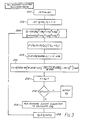
- the calculating and delay assembly 68 is shown in a highly schematic manner in Fig. 2. This assembly 68 will now be described, although it should be understood that the blocks referred to below do not necessarily represent separate physical parts of the apparatus but may instead represent separate parts of an overall software program operated by a single microprocessor or other calculating device.
- the temperature signal from the temperature sensor 52 is provided to a calculating block 122.
- the calculating block 122 calculates from the temperature signal supplied by the temperature sensor 52 and from the known pressure of vapor leaving the outlet 58 of the vaporizing section of the first stage evaporator 32, the concentration of solids in the intermediate liquid mixture flowing along the line 62.
- Figure 3 shows schematically the manner in which the calculation block 122 calculates the concentration of sugars (and hence the proportions of sugar and water) in the intermediate liquid mixture from the temperature sensed by the temperature sensor 52.
- the calculating block 122 comprises a microprocessor programmed to calculate the proportions of sugar and water in the intermediate liquid mixture by an iterative calculation comprising the steps of:
- step b) is effected by first calculating from the estimated proportion of the sugar an estimated activity of the water admixed with the sugar and thereafter calculating the estimated boiling temperature from this estimated activity.
- the estimated activity of the water is calculated by expressing it as an exponent of a fifth order polynomial (using the five-suffix Margules equation) of the proportion of the sugar in the intermediate liquid mixture.
- the program calculates separate estimated water activities, the first estimated activity being calculated as if all the solids were sucrose and the second estimated activity being calculated as if all the solids were corn syrup solids. Then, the program averages these two estimated activities on a basis weighted to correspond to the molar proportions of sucrose and corn syrup solids present in the intermediate liquid mixture to produce a final estimated activity from which the estimated temperature is thereafter calculated.
- the program begins with an initialization block such as will be familiar to those skilled in the art of computer programming.
- the proportion of sugar, X2 is set equal to a constant K, which is chosen arbitrarily as equal to the approximate expected proportion of sugar in the intermediate liquid mixture to provide a reasonable starting point for the following iterative calculations.
- the proportion of water, X1, in the intermediate liquid feed is set equal to 1-K.
- X cs and X s are the number of moles of corn syrup solids and sucrose respectively in the sugar feed solution. It will be apparent to those skilled in the art that if more than two different materials are present in the non-volatile component of the mixture being evaporated, blocks 204 and 206 may be modified to allow for the calculation and averaging of more than two activities.
- the program proceeds, at block 208, to calculate a saturated steam pressure P from the average estimated activity, Gamma, calculated at block 206.
- the formula used in block 208 is a standard thermodynamic formula based upon Raoult's Law, and will be familiar to those skilled in the art of thermodynamics.
- the program proceeds, at block 210, to calculate an estimated boiling temperature from this saturated steam pressure.
- the equation in block 210 is the standard Antoine thermodynamic equation, which will be familiar to those skilled in the art, for the calculation of the boiling temperature of water, i.e., the temperature at which water is in equilibrium with steam at any pressure.
- the program calculates, at block 212, the temperature difference, F, between the estimated boiling temperature T calculated at block 210 and the measured boiling temperature T M read from the temperature sensor 52. Then, at block 214, the modulus of the temperature difference F is determined, and if this modulus is less than 0.1 (this figure is chosen arbitrarily and may be varied depending upon the accuracy needed in a particular application) the estimated proportion of sugar, X2, is deemed to be sufficiently close to the actual sugar concentration to be output to the control block 124 ( Figure 2).
- the program proceeds, at block 216, to run a bounded secant algorithm to calculate an appropriate correction ⁇ X2 to the estimated proportion X2 of sugar.
- bounded secant algorithms are well known to those skilled in the art and may be found in any textbook on mathematical methods or numerical analysis. Other trial and error search techniques, for example the Newton-Rhapson method, may be used if desired.
- the program adds ⁇ X2 to X2 to provide a new value of X2, and then loops back to block 204 to proceed to calculate the new estimated activities using the new value of X2.
- the program just described actually effects the calculations needed to calculate the proportion of water in the intermediate liquid mixture from the boiling temperature.
- the apparatus shown in Figure 1 is to be used to effect the evaporation of a solution of a mixture containing a substantially constant ratio of sugars and only a limited variation in the proportion of sugar in the solution is to be expected (as will frequently be the case under industrial conditions)
- the proportion of water can be calculated with sufficient accuracy by storing a limited number of pairs of values of the boiling temperature and corresponding water contents, and linearly intrapolating between adjacent pairs of values to determine the water content corresponding to the measured boiling temperature.
- the calculations block 122 passes a signal representative of the water content of the intermediate liquid mixture to a control block 124.
- This control block 124 also receives the temperature signal from the temperature sensor 66 and the flow rate reading from the flow sensor 82.
- h s is conveniently taken at 895.8 BTU/lb.
- h f is the heat of vaporization of moisture from the product, and for sugar solutions may be assumed to be 954.45 BTU/lb.
- x i is the solids mass fraction in the intermediate liquid mixture fed to the second stage evaporator
- x o is the desired solids mass fraction in the final product
- the steam flow to the heating section 88 should not be changed immediately, at least in industrial-sized apparatus, in which the residence time in the second stage is significant (typically about 3 to 4 minutes). If, for example, the steam flow needs to be adjusted because the temperature sensed by the sensor 66 drops, immediately after the change in temperature is sensed by the sensor 66 the second stage will still be full of good product, and an immediate change in steam flow would spoil this material.
- the control action must then overcompensate for the "bad" material already in the heating section 88, and for the lag required to overcome the thermal momentum of the system, so that the "bad” material will reach the proper temperature (and hence concentration) during its remaining residence time in the second stage.
- the necessary control action can be accomplished using a dead time lag and then a lead action compensation.
- Electronic modules for providing appropriate dead time lags and lead action compensations are available "off-the-shelf" for some evaporator control systems, e.g., the Foxboro SPEC 200 controller.
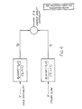
- FIG. 4 of the accompanying drawings shows schematically the dependence of the enthalpy deviation (Y*) of the final liquid mixture on the enthalpy deviation (Z) of the intermediate liquid mixer entering the heating section 88 and on the steam flow deviation (X) to the heating section 88, where in each case "deviation” means the difference between the actual and the steady-state values.
- the process transfer functions are shown in the Laplace domain rather than as differential equations representing the rate of change with respect to time of the temperature at the outlet of the second stage, since the use of Laplace transforms enables the differential equations to be solved algebraically.
- the constants K1, K2, t1, t2, T1 and T2 can be determined empirically by operating the second stage of the evaporator under steady-state conditions, switching off the automatic control, then manually initiating a step change (large enough to be easily measured) in the steam flow rate or the enthalpy of the intermediate liquid mixture, and recording the final mixture outlet temperature as a function of time. Analysis of the resultant temperature/time curves enables the constants to be calculated by methods well known to those skilled in the art.
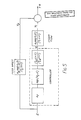
- Figure 5 shows the steps carried out by the calculating and delay assembly 68.
- the objective is that, under any set of circumstances Y* must be zero, which requires:
- T LD s + 1)(T LG s + 1) is the lead-lag expression for the apparatus with T LD being the amount of lead action and T LG the amount of lag action.
- T LD being the amount of lead action
- T LG the amount of lag action.
- modules for providing appropriate values of these parameters are available commercially.
- the function exp(-t f s) is a pure dead time delay, while K f represents the conversion of changes in the enthalpy of the intermediate liquid mixture to changes in stream flow, and is calculated by the control block 124, as already described.
- K1 and K2 vary significantly with operating conditions. Accordingly, rather than attempting to use constant values of K1 and K2, K f is calculated directly in the manner already described.
- the values of the other constants are much less dependent on process conditions and no serious error is introduced by treating them as true constants, since they are based upon material thermal capacitance, which does not change significantly within the temperature range over which any two-stage evaporator would normally be employed for the evaporation of a specific solution.
- the calculation of K f shown in Figure 5 is carried out by the control block 124 shown in Figure 2.
- the calculation of the deadtime shown in Figure 5 is carried out by a delay block 126 shown in Figure 2, while the leadlag factor (T LD s + 1)/(T LG s + 1) is set as already described.
- the calculation of the steam flow response factor shown in Figure 5 is carried out by a calculating block 128 shown in Figure 2 which thus produces a signal representing Y1.
- the response to feed upset factor shown in Figure 5 is calculated by a calculating block 130 shown in Figure 2, which thus produces a signal representative of Y2.
- the summing of the signals representing Y1 and Y2 is effected by a summing block 132 shown in Figure 2. This summing block sends a signal along a line 134 ( Figure 1) to control the operation of the steam flow controller 94.
Landscapes
- Chemical & Material Sciences (AREA)
- Chemical Kinetics & Catalysis (AREA)
- Crystallography & Structural Chemistry (AREA)
- Life Sciences & Earth Sciences (AREA)
- Biochemistry (AREA)
- Organic Chemistry (AREA)
- Vaporization, Distillation, Condensation, Sublimation, And Cold Traps (AREA)
- Sampling And Sample Adjustment (AREA)
- Detergent Compositions (AREA)
Priority Applications (1)
| Application Number | Priority Date | Filing Date | Title |
|---|---|---|---|
| AT87302521T ATE82696T1 (de) | 1986-03-25 | 1987-03-24 | Verfahren und vorrichtung zur kontrolle der zusammensetzung einer die abdampfvorrichtung verlassenden mischung. |
Applications Claiming Priority (2)
| Application Number | Priority Date | Filing Date | Title |
|---|---|---|---|
| US84363286A | 1986-03-25 | 1986-03-25 | |
| US843632 | 1986-03-25 |
Publications (3)
| Publication Number | Publication Date |
|---|---|
| EP0244079A2 true EP0244079A2 (fr) | 1987-11-04 |
| EP0244079A3 EP0244079A3 (en) | 1989-02-22 |
| EP0244079B1 EP0244079B1 (fr) | 1992-11-25 |
Family
ID=25290567
Family Applications (1)
| Application Number | Title | Priority Date | Filing Date |
|---|---|---|---|
| EP87302521A Expired - Lifetime EP0244079B1 (fr) | 1986-03-25 | 1987-03-24 | Procédé et appareil por contrôler la composition d'un mélange quittant un évaporateur |
Country Status (9)
| Country | Link |
|---|---|
| EP (1) | EP0244079B1 (fr) |
| JP (1) | JPS62277103A (fr) |
| AT (1) | ATE82696T1 (fr) |
| AU (1) | AU605141B2 (fr) |
| CA (1) | CA1326811C (fr) |
| DE (1) | DE3782763T2 (fr) |
| ES (1) | ES2035044T3 (fr) |
| GR (1) | GR3006811T3 (fr) |
| NZ (1) | NZ219755A (fr) |
Cited By (2)
| Publication number | Priority date | Publication date | Assignee | Title |
|---|---|---|---|---|
| EP0515765A1 (fr) * | 1991-02-23 | 1992-12-02 | Unipektin Ag | Dispositif d'évaporation et procédé de sa mise en oeuvre |
| EP0949204A1 (fr) * | 1998-04-10 | 1999-10-13 | Della Toffola France S.A. | Procédés et dispositifs biophysiques de traitement d'eaux résiduaires sucrées ou alcoolisées |
Families Citing this family (2)
| Publication number | Priority date | Publication date | Assignee | Title |
|---|---|---|---|---|
| US20250178943A1 (en) * | 2021-03-11 | 2025-06-05 | Ellen Medical Devices Pty Ltd | System, method and device for treating a liquid |
| US20240218470A1 (en) * | 2023-01-04 | 2024-07-04 | John Vela | System for the Removal of Water Vapor from Molasses or other High Sugar Concentrate Substances and Method for Operating Same |
Family Cites Families (6)
| Publication number | Priority date | Publication date | Assignee | Title |
|---|---|---|---|---|
| BE430875A (fr) * | ||||
| FR2101257A5 (fr) * | 1970-03-19 | 1972-03-31 | Fives Lille Cail | |
| US4056364A (en) * | 1974-08-30 | 1977-11-01 | Amstar Corporation | Two stage continuous crystallization apparatus with controls |
| US3981739A (en) * | 1974-08-30 | 1976-09-21 | Amstar Corporation | Continuous crystallization |
| FR2508672B1 (fr) * | 1981-06-24 | 1985-07-05 | Fives Cail Babcock | Procede et systeme de regulation d'un appareil de cristallisation a marche continue notamment pour la production de sucre |
| JPS6115700A (ja) * | 1984-07-03 | 1986-01-23 | 横河電機株式会社 | 結晶缶プログラム制御方法 |
-
1987
- 1987-03-24 CA CA000532856A patent/CA1326811C/fr not_active Expired - Fee Related
- 1987-03-24 NZ NZ219755A patent/NZ219755A/xx unknown
- 1987-03-24 ES ES198787302521T patent/ES2035044T3/es not_active Expired - Lifetime
- 1987-03-24 AT AT87302521T patent/ATE82696T1/de active
- 1987-03-24 EP EP87302521A patent/EP0244079B1/fr not_active Expired - Lifetime
- 1987-03-24 DE DE8787302521T patent/DE3782763T2/de not_active Expired - Fee Related
- 1987-03-25 JP JP62069253A patent/JPS62277103A/ja active Pending
- 1987-03-25 AU AU70609/87A patent/AU605141B2/en not_active Ceased
-
1993
- 1993-01-14 GR GR930400066T patent/GR3006811T3/el unknown
Cited By (3)
| Publication number | Priority date | Publication date | Assignee | Title |
|---|---|---|---|---|
| EP0515765A1 (fr) * | 1991-02-23 | 1992-12-02 | Unipektin Ag | Dispositif d'évaporation et procédé de sa mise en oeuvre |
| EP0949204A1 (fr) * | 1998-04-10 | 1999-10-13 | Della Toffola France S.A. | Procédés et dispositifs biophysiques de traitement d'eaux résiduaires sucrées ou alcoolisées |
| FR2777271A1 (fr) * | 1998-04-10 | 1999-10-15 | Della Toffola France Sa | Procedes et dispositifs biophysiques de traitement d'eaux residuaires sucrees ou alcoolisees |
Also Published As
| Publication number | Publication date |
|---|---|
| DE3782763T2 (de) | 1993-04-29 |
| EP0244079A3 (en) | 1989-02-22 |
| AU7060987A (en) | 1987-10-01 |
| JPS62277103A (ja) | 1987-12-02 |
| GR3006811T3 (fr) | 1993-06-30 |
| NZ219755A (en) | 1989-01-06 |
| CA1326811C (fr) | 1994-02-08 |
| DE3782763D1 (de) | 1993-01-07 |
| ATE82696T1 (de) | 1992-12-15 |
| EP0244079B1 (fr) | 1992-11-25 |
| ES2035044T3 (es) | 1993-04-16 |
| AU605141B2 (en) | 1991-01-10 |
Similar Documents
| Publication | Publication Date | Title |
|---|---|---|
| US4251224A (en) | Control system for chlorine dioxide plants | |
| Shinskey | Controlling multivariable processes | |
| MXPA01008096A (es) | Procedimiento para la fabricacion de furfural. | |
| Sorour | Optimization of multiple effect evaporators designed for fruit juice concentrate | |
| RU2722132C1 (ru) | Способ управления ректификационной колонной выделения изопентана | |
| EP0244079A2 (fr) | Procédé et appareil por contrôler la composition d'un mélange quittant un évaporateur | |
| US3050450A (en) | Extractive distillation control | |
| GB1316706A (en) | Process and system for regulating a crystalising installation operating by evaporation and continuously for the crystalli sation of sugar or similar products | |
| US2748849A (en) | Automatic control of concentrating evaporators | |
| Castro et al. | Dynamic simulation of multiple-effect evaporation | |
| US6869501B2 (en) | Continuous process for controlled concentration of colloidal solutions | |
| CN113195073B (zh) | 带有软传感器的热分离方法 | |
| Damour et al. | Multivariable linearizing control of an industrial sugar crystallization process | |
| US3434934A (en) | Control system for fractional distillation columns | |
| US3212283A (en) | Crystallized solids content control system | |
| US3356124A (en) | Control arrangement for a multiple effect evaporator | |
| Randall et al. | Feedforward‐feedback control of a vertical long‐tube tomato evaporator. 1. Analog simulation | |
| US4417311A (en) | Fractional distillation column control | |
| James et al. | Heat transfer, mass transfer and scaling characteristics in a long tube, climbing film, pilot plant evaporator | |
| SU1124988A2 (ru) | Способ регулировани процесса выпаривани | |
| SU1261684A1 (ru) | Способ автоматического регулировани процесса ректификации | |
| SU1037923A1 (ru) | Способ автоматического управлени процессом выпаривани | |
| SU1018662A1 (ru) | Способ автоматического управлени процессом выпаривани | |
| SU1124035A1 (ru) | Способ регулировани процесса кристаллизации сахаросодержащих растворов | |
| JPS61259701A (ja) | 濃縮方法およびその装置 |
Legal Events
| Date | Code | Title | Description |
|---|---|---|---|
| PUAI | Public reference made under article 153(3) epc to a published international application that has entered the european phase |
Free format text: ORIGINAL CODE: 0009012 |
|
| AK | Designated contracting states |
Kind code of ref document: A2 Designated state(s): AT BE CH DE ES FR GB GR IT LI LU NL SE |
|
| PUAL | Search report despatched |
Free format text: ORIGINAL CODE: 0009013 |
|
| AK | Designated contracting states |
Kind code of ref document: A3 Designated state(s): AT BE CH DE ES FR GB GR IT LI LU NL SE |
|
| 17P | Request for examination filed |
Effective date: 19890729 |
|
| RAP1 | Party data changed (applicant data changed or rights of an application transferred) |
Owner name: SOCIETE DES PRODUITS NESTLE S.A. |
|
| 17Q | First examination report despatched |
Effective date: 19910607 |
|
| ITF | It: translation for a ep patent filed | ||
| GRAA | (expected) grant |
Free format text: ORIGINAL CODE: 0009210 |
|
| AK | Designated contracting states |
Kind code of ref document: B1 Designated state(s): AT BE CH DE ES FR GB GR IT LI LU NL SE |
|
| REF | Corresponds to: |
Ref document number: 82696 Country of ref document: AT Date of ref document: 19921215 Kind code of ref document: T |
|
| REF | Corresponds to: |
Ref document number: 3782763 Country of ref document: DE Date of ref document: 19930107 |
|
| ET | Fr: translation filed | ||
| REG | Reference to a national code |
Ref country code: ES Ref legal event code: FG2A Ref document number: 2035044 Country of ref document: ES Kind code of ref document: T3 |
|
| REG | Reference to a national code |
Ref country code: GR Ref legal event code: FG4A Free format text: 3006811 |
|
| PLBE | No opposition filed within time limit |
Free format text: ORIGINAL CODE: 0009261 |
|
| STAA | Information on the status of an ep patent application or granted ep patent |
Free format text: STATUS: NO OPPOSITION FILED WITHIN TIME LIMIT |
|
| 26N | No opposition filed | ||
| EPTA | Lu: last paid annual fee | ||
| EAL | Se: european patent in force in sweden |
Ref document number: 87302521.7 |
|
| ITTA | It: last paid annual fee | ||
| PGFP | Annual fee paid to national office [announced via postgrant information from national office to epo] |
Ref country code: GR Payment date: 19961230 Year of fee payment: 11 |
|
| PGFP | Annual fee paid to national office [announced via postgrant information from national office to epo] |
Ref country code: FR Payment date: 19970313 Year of fee payment: 11 Ref country code: AT Payment date: 19970313 Year of fee payment: 11 |
|
| PGFP | Annual fee paid to national office [announced via postgrant information from national office to epo] |
Ref country code: GB Payment date: 19970317 Year of fee payment: 11 |
|
| PGFP | Annual fee paid to national office [announced via postgrant information from national office to epo] |
Ref country code: SE Payment date: 19970319 Year of fee payment: 11 |
|
| PGFP | Annual fee paid to national office [announced via postgrant information from national office to epo] |
Ref country code: ES Payment date: 19970324 Year of fee payment: 11 |
|
| PGFP | Annual fee paid to national office [announced via postgrant information from national office to epo] |
Ref country code: NL Payment date: 19970327 Year of fee payment: 11 |
|
| PGFP | Annual fee paid to national office [announced via postgrant information from national office to epo] |
Ref country code: DE Payment date: 19970401 Year of fee payment: 11 |
|
| PGFP | Annual fee paid to national office [announced via postgrant information from national office to epo] |
Ref country code: CH Payment date: 19970408 Year of fee payment: 11 |
|
| PGFP | Annual fee paid to national office [announced via postgrant information from national office to epo] |
Ref country code: LU Payment date: 19970425 Year of fee payment: 11 |
|
| PGFP | Annual fee paid to national office [announced via postgrant information from national office to epo] |
Ref country code: BE Payment date: 19970521 Year of fee payment: 11 |
|
| PG25 | Lapsed in a contracting state [announced via postgrant information from national office to epo] |
Ref country code: LU Free format text: LAPSE BECAUSE OF NON-PAYMENT OF DUE FEES Effective date: 19980324 Ref country code: GB Free format text: LAPSE BECAUSE OF NON-PAYMENT OF DUE FEES Effective date: 19980324 Ref country code: AT Free format text: LAPSE BECAUSE OF NON-PAYMENT OF DUE FEES Effective date: 19980324 |
|
| PG25 | Lapsed in a contracting state [announced via postgrant information from national office to epo] |
Ref country code: SE Free format text: LAPSE BECAUSE OF NON-PAYMENT OF DUE FEES Effective date: 19980325 Ref country code: ES Free format text: LAPSE BECAUSE OF NON-PAYMENT OF DUE FEES Effective date: 19980325 |
|
| PG25 | Lapsed in a contracting state [announced via postgrant information from national office to epo] |
Ref country code: LI Free format text: LAPSE BECAUSE OF NON-PAYMENT OF DUE FEES Effective date: 19980331 Ref country code: GR Free format text: LAPSE BECAUSE OF NON-PAYMENT OF DUE FEES Effective date: 19980331 Ref country code: FR Free format text: THE PATENT HAS BEEN ANNULLED BY A DECISION OF A NATIONAL AUTHORITY Effective date: 19980331 Ref country code: CH Free format text: LAPSE BECAUSE OF NON-PAYMENT OF DUE FEES Effective date: 19980331 Ref country code: BE Free format text: LAPSE BECAUSE OF NON-PAYMENT OF DUE FEES Effective date: 19980331 |
|
| BERE | Be: lapsed |
Owner name: SOC. DES PRODUITS NESTLE S.A. Effective date: 19980331 |
|
| PG25 | Lapsed in a contracting state [announced via postgrant information from national office to epo] |
Ref country code: NL Free format text: LAPSE BECAUSE OF NON-PAYMENT OF DUE FEES Effective date: 19981001 |
|
| GBPC | Gb: european patent ceased through non-payment of renewal fee |
Effective date: 19980324 |
|
| REG | Reference to a national code |
Ref country code: CH Ref legal event code: PL |
|
| NLV4 | Nl: lapsed or anulled due to non-payment of the annual fee |
Effective date: 19981001 |
|
| PG25 | Lapsed in a contracting state [announced via postgrant information from national office to epo] |
Ref country code: DE Free format text: LAPSE BECAUSE OF NON-PAYMENT OF DUE FEES Effective date: 19981201 |
|
| EUG | Se: european patent has lapsed |
Ref document number: 87302521.7 |
|
| REG | Reference to a national code |
Ref country code: FR Ref legal event code: ST |
|
| REG | Reference to a national code |
Ref country code: ES Ref legal event code: FD2A Effective date: 20010503 |
|
| PG25 | Lapsed in a contracting state [announced via postgrant information from national office to epo] |
Ref country code: IT Free format text: LAPSE BECAUSE OF NON-PAYMENT OF DUE FEES;WARNING: LAPSES OF ITALIAN PATENTS WITH EFFECTIVE DATE BEFORE 2007 MAY HAVE OCCURRED AT ANY TIME BEFORE 2007. THE CORRECT EFFECTIVE DATE MAY BE DIFFERENT FROM THE ONE RECORDED. Effective date: 20050324 |