EP0243920A2 - Mikrofilmaufzeichnungssystem - Google Patents
Mikrofilmaufzeichnungssystem Download PDFInfo
- Publication number
- EP0243920A2 EP0243920A2 EP87106090A EP87106090A EP0243920A2 EP 0243920 A2 EP0243920 A2 EP 0243920A2 EP 87106090 A EP87106090 A EP 87106090A EP 87106090 A EP87106090 A EP 87106090A EP 0243920 A2 EP0243920 A2 EP 0243920A2
- Authority
- EP
- European Patent Office
- Prior art keywords
- film
- reel
- canister
- receiving
- pair
- Prior art date
- Legal status (The legal status is an assumption and is not a legal conclusion. Google has not performed a legal analysis and makes no representation as to the accuracy of the status listed.)
- Withdrawn
Links
- 230000003287 optical effect Effects 0.000 claims description 13
- 230000011664 signaling Effects 0.000 claims description 7
- 230000004044 response Effects 0.000 claims description 6
- 239000010935 stainless steel Substances 0.000 claims description 4
- 229910001220 stainless steel Inorganic materials 0.000 claims description 4
- 229910001092 metal group alloy Inorganic materials 0.000 claims description 2
- 239000012858 resilient material Substances 0.000 claims description 2
- 238000000926 separation method Methods 0.000 claims 1
- 230000007246 mechanism Effects 0.000 abstract description 11
- 230000006870 function Effects 0.000 description 3
- 238000007373 indentation Methods 0.000 description 3
- 238000013461 design Methods 0.000 description 2
- 238000010586 diagram Methods 0.000 description 2
- 238000000034 method Methods 0.000 description 2
- 238000012986 modification Methods 0.000 description 2
- 230000004048 modification Effects 0.000 description 2
- 230000008569 process Effects 0.000 description 2
- 239000013598 vector Substances 0.000 description 2
- 229910000831 Steel Inorganic materials 0.000 description 1
- 238000013459 approach Methods 0.000 description 1
- 238000010276 construction Methods 0.000 description 1
- 230000008878 coupling Effects 0.000 description 1
- 238000010168 coupling process Methods 0.000 description 1
- 238000005859 coupling reaction Methods 0.000 description 1
- 230000000694 effects Effects 0.000 description 1
- 238000012544 monitoring process Methods 0.000 description 1
- 230000002093 peripheral effect Effects 0.000 description 1
- 239000010959 steel Substances 0.000 description 1
Images


Classifications
-
- G—PHYSICS
- G03—PHOTOGRAPHY; CINEMATOGRAPHY; ANALOGOUS TECHNIQUES USING WAVES OTHER THAN OPTICAL WAVES; ELECTROGRAPHY; HOLOGRAPHY
- G03B—APPARATUS OR ARRANGEMENTS FOR TAKING PHOTOGRAPHS OR FOR PROJECTING OR VIEWING THEM; APPARATUS OR ARRANGEMENTS EMPLOYING ANALOGOUS TECHNIQUES USING WAVES OTHER THAN OPTICAL WAVES; ACCESSORIES THEREFOR
- G03B27/00—Photographic printing apparatus
- G03B27/32—Projection printing apparatus, e.g. enlarger, copying camera
- G03B27/46—Projection printing apparatus, e.g. enlarger, copying camera for automatic sequential copying of different originals, e.g. enlargers, roll film printers
- G03B27/47—Projection printing apparatus, e.g. enlarger, copying camera for automatic sequential copying of different originals, e.g. enlargers, roll film printers at different positions of the same sheet, e.g. microfiche
-
- G—PHYSICS
- G03—PHOTOGRAPHY; CINEMATOGRAPHY; ANALOGOUS TECHNIQUES USING WAVES OTHER THAN OPTICAL WAVES; ELECTROGRAPHY; HOLOGRAPHY
- G03B—APPARATUS OR ARRANGEMENTS FOR TAKING PHOTOGRAPHS OR FOR PROJECTING OR VIEWING THEM; APPARATUS OR ARRANGEMENTS EMPLOYING ANALOGOUS TECHNIQUES USING WAVES OTHER THAN OPTICAL WAVES; ACCESSORIES THEREFOR
- G03B15/00—Special procedures for taking photographs; Apparatus therefor
- G03B15/003—Apparatus for photographing CRT-screens
Definitions
- This invention relates to a reel-to-reel microfilm recorder system which may be operated automatically under control of a computer or other control device.
- microfilm recorder systems commonly called computer-output microfilm recorders (COM).
- COM computer-output microfilm recorders
- Such systems are used for storing vast amounts of data, either alphanumeric, graphic, or both, on film.
- the most common type system utilizes rolls of microfilm which, after the film is exposed and developed, are cut into sheets called microfiche.
- microfilm recorder systems which, rather than using rolls of microfilm, copy data onto single, pre-cut sheets of microfilm.
- the individual sheets are held in cartridges which are loaded into the system prior to exposure of the sheets. After exposure, the cartridges are removed from the system for developing the microfilm sheets.
- microfilm recorder systems whether of the type which use rolls of microfilm or of the type which use single, pre-cut film sheets, are generally complicated and costly in design and constuction, cumbersome and somewhat time consuming to initialize and use, and relatively difficult to load, unload and service.
- the above and other objects and advantages of the invention are realized in a specific illustrative embodiment of a microfilm recorder system for recording optical images on reel-wound film.
- the system includes a frame, a film supply canister mountable on the frame for holding a roll of microfilm, a film take-up canister insertable on and removable from the frame for receiving the film from the film supply canister, and a film transporting mechanism for moving the film for exposure between the film supply canister and the film take-up canister.
- the film take-up canister includes a reel on which the film is wound when the reel is rotated, and a driven gear which, when driven, causes the reel to rotate. When the film take-up canister is inserted onto the frame, the driven gear automatically engages a driving gear which may be in the form of a toothed belt, gear wheel, etc.
- the frame includes an exposure section located between the film supply canister and the film take-up canister over which film travels after it is withdrawn from the film supply canister and before it is delivered to the film take-up canister.
- the frame also includes a first pair of generally parallel, spaced-apart rails extending in one direction from the exposure section, and a second pair of generally parallel, spaced-apart rails extending in the opposite direction from the exposure section.
- the film supply canister and the film take-up "canister each include a pair of generally parallel tracks located on opposite sides thereof for receiving a corresponding pair of rails when the canisters are inserted between those rails.
- the rails and tracks on the canisters serve to properly align the canisters for withdrawing film from the supply canister and supplying it to the take-up canister.
- the canisters are automatically locked in position when inserted a predetermined distance onto corresponding rails.
- film guides are attached to the film supply canister and the film take-up canister.
- the guides define generally planar slots for aligning and guiding the film between the film supply canister and the film take-up canister.
- the mechanical features described above may be operated under control of a stored program microprocessor which would both control movement of the microfilm, and monitor the film supply canister to terminate movement of the film when all of the film has been withdrawn from the film supply canister.
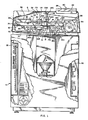
- the microfilm recorder system includes a cabinet 4 in which are housed the system electronics, and on which are mounted mechanical apparatus to be discussed momentarily.
- a cover 6 is hingedly mounted on the cabinet 4 so that it can be raised to allow access to the mechanical apparatus or lowered to cover such apparatus.
- a cathode ray tube 8 is disposed in the cabinet 4 and is directed upwardly toward a base plate 10 which is mounted on the cabinet.
- a generally hollow cylindrical lens support base 12 is mounted on the base plate 10 about an opening in the base plate.
- An optical focusing lens 16 is carried by the support base 12 in line with the cathode ray tube 8 to focus the picture produced by the cathode ray tube onto a film plane 18 defined by the top of the lens.
- a control panel 20, including control buttons and switches 22 and a display window 24 is mounted on the top and at one side of the cover 6 to allow a user to initialize and control operation of the microfilm recorder system.
- the electronic circuitry for controlling operation of the system is housed behind the panel 20 and within the cabinet 4 on boards 25 and 26. All features described thus far are conventional in a microfilm recorder system.
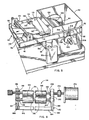
- a frame 30 consisting of brackets 30a, 30b, 30c and 30d upstanding from the base plate 10 (see FIG. 2).
- a pair of rods 31 and 32 are mounted to extend between brackets 30a and 30d, and 30b and 30c respectively.
- the assembly 34 includes a carriage plate 36 which is mounted on the four mounts 33a, 33b, 33c and 33d, and a pair of generally parallel rails 38 and 42 mounted on the plate 36 to extend above and on each side of a film exposure section 46 over which microfilm will pass for exposure to images produced by the cathode ray tube 8 and focused by the optical focusing lens 16.
- the rails 38 and 42 are provided for holding at opposite ends thereof a film supply canister 50 and a film take-up or receiving canister 54.
- the supply canister 50 is for holding a reel of microfilm which is to be transported or delivered to the exposure section 46 and then wound on a reel contained in the take-up canister 54.
- the canisters 50 and 54 are formed with four side walls and a bottom wall, with an opening at the top which is covered by lids 56 and 58 (FIG. 1).
- each of the canisters 50 and 54 Located on each side of each of the canisters 50 and 54 are a pair of tracks (60 and 62 for the supply canister 50, and 64 and 66 for the take-up canister 54).
- the track 62 As best seen in FIG. 5 for the supply canister 50, the track 62, as with the other tracks, is formed generally to define a channel into which a corresponding rail, such as rail 42, may be inserted.
- the tracks 60, 62, 64 and 66 and rails 38 and 42 are arranged so that when the canisters 50 and 54 are inserted between the rails, the canisters are aligned on opposite sides of the exposure section 46.
- the rails 38 and 42 thus serve to both support the canisters 50 and 54 as well as guide and align the canisters.
- Detent spring elements hold the canisters in place between the rails 38 and 42.
- the detent spring elements such as elements 70, 74 (FIG. 1) and 78 and 82 (FIG. 2), each consist of openings or indentations in the canister tracks and spring loaded plungers or ball detents disposed in the rail 38 (two at the top edge of the rail and two at the bottom edge).
- the plungers move into the openings or indentations formed in the tracks. With the plungers moving into the respective openings or indentations, the two canisters 50 and 54 are locked in place on the rails 38 and 42 in proper alignment.
- the canisters may be removed from the rails by simply pulling back on the canisters and sliding the canisters off the free ends of the rails.
- the canisters 50 and 54 are each adapted to hold reels on which may be wound rolls of microfilm.
- a reel 90 is shown mounted in a canister 50 and a reel 94 is shown mounted in canister 54.
- the reels 90 and 94 are conventional microfilm reels having central bores to enable mounting the reels in the canisters in a conventional fashion.
- reel 94 would be mounted in canister 54 by removing the canister lid, pulling back on a spring-loaded plunger 98 mounted on the side wall of the canister 54, placing the reel 94 in the canister and inserting one end of the central bore of the reel over a rotatable axle 102 which extends through the other side wall of the canister 54, aligning the other end of the reel 94 with the plunger 98 and then releasing the plunger so that the mounting end 106 extends into the central bore of the reel.
- the reel 90 would be mounted in a similar fashion in canister 50 and since canister 50 is the supply canister, the reel 90 with a roll of microfilm would be mounted in the canister in a dark room to prevent exposure of the film.
- the film guide 110 is shown as comprising an upper plate 116 and a lower plate 118, with the latter positioned below the former and formed to define a latitudinal and longitudinal slot 120 therebetween. Disposed at one side of the slot 120 between the plates 116 and 118 is a stainless steel edge guide 122.
- the edge guide includes a slot 123 for holding and guiding one edge of microfilm moving through the film guide 110.
- the guide 110 is provided to smooth, flatten and align the film as it leaves the supply canister 50 and approaches the roller assembly 114.
- a similar film guide 124 is attached to the front wall of the film take-up canister 54 as best seen in FIG. 2.
- the film guide 124 includes stainless steel edge guides on both sides of the film guide slot, to hold and guide both edges of the microfilm.
- the film, shown at 126 in FIG. 1, after it leaves the roller assembly 114 is threaded through the film guide 124 into the take-up canister 54 where it is then threaded into the slot of the reel mounted in the canister (such a slot is shown at 130 in the reel 90 of FIG. 5).
- the roller assembly 114 is shown in greater detail in FIG. 6.
- the assembly includes a pair of rollers 134 and 136, one positioned above the other.
- the upper roller which is made of steel or other metallic alloy, is smaller in diameter and circumference than the lower roller which is made of rubber or similar resilient material. Provision of a larger lower roller provides for better gripping and thus improved film tracking since there is a greater contact area of the film by the rollers.
- the rollers 134 and 136 are respectively mounted on axles 140 and 144.
- the axles are mounted to rotate about their long axes in bearings 146, 148, 150 and 152 which, in turn, are held by brackets 156 and 160.
- the brackets 156 and 160 are mounted on a brace 164 which extends between rails 38 and 42 as best seen in FIG. 5.
- the rollers are thus positioned near the film guide 110 of the supply canister 50 to grip and move the film from the supply canister towards the take-up canister 54.
- the spacing between the rollers 134 and 136 may be adjusted by adjusting screws 166 and 168 which are positioned below dowels 167 and 169 which support bearings 152 and 150 respectively in the brackets 156 and 160.
- the screws 166 and 168 are screwed into bores formed in the brackets 156 and 160 to contact the dowels 167 and 169 which in turn contact the bearings 152 and 150 and either raise or lower the bearings which rest on the dowels
- the roller assembly 114 is powered by a stepper motor 170 which is coupled by a mechanical coupling 172 (FIG. 6) to the upper roller 134.
- the stepper motor 170 causes the upper roller 134 to rotate and move film positioned between the two rollers from the supply canister 50 over the film exposure section 46 to the take-up canister 54.
- the stepper motor 170 operates under control of a microprocessor housed in the cabinet 4, as will be described later.
- the microprocessor may be prcgrammed to cause advancement of the film by various size increments to position unexposed film over the film exposure section 46.
- the film take-up canister 54 receives microfilm after it has passed over the film exposure section 46 (FIG. 3).
- the take-up canister 54 includes a reel 94 onto which the leading end of the film is threaded.
- the reel 94 is caused to rotate to take up any slack in the film and to wind the film on the reel after it has been exposed.
- the reel is caused to rotate by a driving mechanism which automatically engages the reel when the take-up canister 94 is inserted in position between rails 38 and 42 to the location where the detent elements lock the canister in place.
- FIG. 4 shows a gear motor 176 mounted on a bracket 180 which extends downwardly from rail 42.
- a gear pulley 184 is mounted on the drive shaft of the motor 176.
- a second gear pulley 188 is mounted to rotate on the rail 42 at a location spaced upwardly and rearwardly from gear pulley 184.
- a double-sided drive belt 192 (has teeth on both sides) extends about each of the gear pulleys 184 and 188 in a longitudinal fashion as shown in FIG. 4.
- the belt 192 includes gaps into which the teeth of gear pulleys 184 and 188 will fit to drive and move the " belt. The belt is caused to move in the direction indicated by the arrows.
- a gear pulley.200 mounted on a slipping clutch assembly 204 which, in turn, is mounted on the canister 54 and coupled to the axle 102 (FIG. 3) automatically engages the drive belt 192. Then, when the drive belt 192 is caused to move by the gear motor 176, the gear pulley 200 is caused to rotate in the direction indicated by the arrows and this, in turn, causes the clutch to turn and cause the axle 102 (FIG. 3) to turn and rotate the reel 94.
- the slipping clutch assembly 204 will apply a certain maximum torque to the reel 94 to cause it to turn and take up any slack in the microfilm 126, but without putting excessive tension on the film. Such a slipping clutch assembly is conventional.
- the microprocessor monitors the film in the supply canister to determine when the film has been withdrawn from the supply canister. When this condition is detected, the microprocessor stops the stepper motor 170 and the gear motor 176 (FIG. 3) so that a portion of the trailing end of the film is left protruding from the take-up canister 54 for easy grasping and subsequent removal.
- FIG. 5 shows a sensing mechanism 208 which includes an optical sensor 212 mounted in a housing 216 which, in turn, is carried by rail 42.
- the housing 216 and optical sensor 212 are positioned above a slipping clutch wheel mechanism 220 which is mounted on axle 100 and which turns with the axle 100 so long as film is being pulled and unwound from the reel 90.
- Alternating dark and light stripes 224 are located on the perimeter of the wheel 220 so that movement (or lack of movement) of the wheel can be detected by the sensor 212.
- the sensor 212 simply supplies a signal to the microprocessor each time movement of the stripes occurs.
- the slipping clutch wheel mechanism 220 causes the axle 100 and thus the wheel itself to stop rotating.
- the slipping clutch wheel mechanism 220 is a conventional device which places a drag or resistance on a rotating element to stop the element if less than a certain force is applied to rotate the element.
- the microprocessor receives no signals from the sensor 212 over some predetermined period of time, it stops operation of the stepper motor and gear motor to stop movement of the film. It should be understood that a variety of sensor elements could be employed to detect movement of the clutch wheel 220 including magnetic sensors and mechanical sensors.
- Movement of the film longitudinally with respect to the focusing lens 16 is accomplished by operation of the roller assembly 114 as previously discussed. Movement laterally is accomplished by moving the entire film transport assembly 34 on the rods 31 and 32.
- a second stepper motor 228 mounted on the base plate 10 is coupled to a belt 232 which, in turn, is coupled to belt bracket 234 (FIG. 3).
- the belt bracket 234 is mounted to the underside of carriage plate 36.
- the belt 232 is looped about pulley 236 which is rotatably mounted in clevis element 240 attached to bracket 30b, and about pulley 244 mounted on the drive shaft of the stepper motor 228.
- the microprocessor controls the stepper motor 228 to move the belt 232 and thus move the film transport assembly laterally with respect to the lens 16.
- a platen assembly 250 mounted on brace 254, is operated by the microprocessor to hold the film 126 against the upper surface 18 of the optical focusing lens 16 FIGS. 1 and 2). This is done D y signaling a solenoid 256 to move a plunger 260 downwardly to press the film 126 against the optical focusing lens 16, and then signaling the solenoid to release the plunger after the film is properly exposed.
- An infrared sensor 270 is mounted under the brace 254 to direct a beam of infrared light toward the enlarged portion of the plunger 260 each time the solenoid 256 is signaled. If the solenoid 256 operates properly to move the plunger 260 downwardly, the infrared beam misses the enlarged portion of the plunger to indicate proper operation. If the solenoid 256 does not operate properly and the plunger 260 is not moved downwardly, the infrared beam strikes the enlarged portion of the plunger and is reflected back to the sensor 270 to indicate improper operation.
- FIG. 7 is a block diagram of an illustrative embodiment of an electronic control system which may be utilized to control operation of the parts of the microfilm recorder system described in FIGS. 1-6.
- a host computer would supply data and control signals via an interface controller 304 and data/address bus 308 to a supervisor microprocessor 312, identifying information to be produced on the cathode ray tube 8 for recording on microfilm.
- the supervisor microprocessor 312 also receives from the control panel 20 data and control signals generated manually by the system operator, and supplies information to the control panel for display on the display screen 24 (FIG. 1).
- the supervisor microprocessor could be any of a number of different microprocessors including the G4180 made by Hitachi.
- the microprocessor 312 In response to received data and control signals, the microprocessor 312 produces data and control signals for controlling the operation of the microfilm recorder system pursuant to programs and information stored in read only memory 316, nonvolatile random access memory 320 and dynamic random access memory 324. Additional information for use by the microprocessor 312 may be stored on floppy disk 328 or hard disk or tape 332.
- the supervisor microprocessor 312 controls production of displays on the cathode ray tube by supplying data and control signals via the data/address bus 308 and a video engine interface 336 to a video engine controller 340.
- the video engine controller 340 receives the data and (1) translates the data into an appropriate graphics pattern if graphics are to be displayed, (2) calculates primitives and vectors if in the vector mode, or (3) supplies the data directly to a video engine 344 if in the bit map mode.
- the video engine 344 receives information from the video engine controller 340 and performs a-number of tasks, including production of video timing signals, performance of the video screen refresh function, and production of low level, medium level and high level drawing commands. In this manner, the video engine 344 controls production of displays on the cathode ray tube 8 and these displays are exposed to the microfilm. All this is well known in the art.
- the supervisor microprocessor 312 also supplies information and commands via the data/address bus 308 and a transport control interface 350 to a transport control microprocessor 354 for the purpose of controlling the stepper motors 170 and 228, the platen assembly 250, including the infrared sensor 270, and other power functions.
- the transport control microprocessor 354 responds by signaling motor drivers 358 and 362, a platen assembly driver 366 and power controllers 370, all via a data/address bus 374 and peripheral interface 378 and pursuant to programs stored in read only memory 382.
- the motor driver 358 controls operation of the stepper motor 170 which advances or retracts the film 126 (to thereby fix the Y coordinate of the image being recorded on the film).
- the motor driver 362 controls operation of the stepper motor 228 which moves the film transport assembly 34 from side to side (to thereby fix the X coordinate of the image being recorded).
- the platen assembly driver 366 operates the platen solenoid 256 and the infrared sensor 270 (to produce a beam of light) and receives back from the sensor a signal indicating whether or not a beam reflection was detected.
- the power controllers 370 generally controls other functions of the microfilm recorder such as film-cut marking, lid locking, and detecting the "film-out" condition. When the "film-out" condition is detected, as earlier described, the stepper motor 170 is ultimately signaled by the transport control microprocessor 354 to stop.
- the supervisor microprocessor 312 supplies information to the transport control microprocessor 354 to signal the motor driver 362 and motor 228 to move the film transport assembly 34 to one side so that the microfilm 126 is moved out_of the exposure area to avoid the effects of the corona from the cathode ray tube 8. If this were not done, then the corona of the CRT 8 could inadvertently expose the film making it unuseable for recording information.
- the recorder system of the present invention is operated by first installing a roll of microfilm in the film supply canister 50, threading the film through the film guide l10, the roller assembly 114, over the optical focusing lens 16 -and below a film platen assembly 250, through the film guide 124 and onto a reel in the take-up canister 54.
- the operator of the system provides input to initialize and initiate operation of the system either via the control panel 20 (FIG. 1) or the interface controller 304 (FIG. 7). After initialization, the system is ready to photograph on microfilm alphanumeric or graphic data either stored in system memory or supplied from the host computer.
- the information to be photographed is appropriately formatted by the supervisor microprocessor 312, as earlier described, and then transferred to the video engine controller 340 and video engine 344 where it is prepared for display on the cathode ray tube 8. While this is taking place, the transport control microprocessor 354 operates the stepper motors 170 and 228 to respectively move the film from the supply canister 50 to the take-up canister 54, and move the transport assembly 34 laterally until the film 126 is positioned at the initial frame location above the focusing lens 16. The transport control microprocessor 354 then activates the platen assembly 250 to hold the film against the upper surface of the focusing lens 16.
- the information to be recorded on the initial frame of the film is supplied to the cathode ray tube 8 which is then unblanked to produce an image of the information. This image is reduced by the focusing lens 16 and a latent image is thereby placed on the film 126. After a predetermined time interval, the cathode ray tube 8 is blanked, the platen assembly 250 is released, and the film and/or film transport assembly 34 are advanced to the next frame position.
- the above-described recording process continues for a predetermined number of rows and columns on the film to make up a complete tiche, after which the supervisor microprocessor 312 temporarily halts any incoming data from the host computer, hard disk, tape, etc.
- An "eye- readable" title is then placed on the film by the cathode ray tube 8 under control of the supervisor microprocessor 312.
- Other information such as data previously extracted during the filming process (e.g. a header from the starting and finishing document) can then be inserted into the title at the discretion of the operator.
- the transport control microprocessor 354 predetermines the status of the film in the supply canister 50 by first advancing the film by three fiche lengths at the beginning of each new fiche, while at the same time monitoring the "film-out" condition by way of the sensing mechanism 208. If it is determined that there is still film in the supply canister 50 (because the wheel 220 is determined to still be moving) at the end of the third fiche, the film is reversed back into the supply canister 50 for two fiche lengths and filming commences. If it is determined that the film supply is depleted (the wheel 220 is determined not to be moving), the optical sensor 212 signals the transport microprocessor 354 that the film is depleted and no more filming should be undertaken until a new roll of film is installed.
- the film When a "film-out" condition is detected, the film is advanced into the take-up canister 54 to protect the latent images from light when the cabinet cover 6 is raised.
- the transport control microprocessor 354 advances the film into the take-up canister 54, but leaves a short trailer portion of the film exposed for easy grasping and removal of the film when it is to be developed.
Landscapes
- Physics & Mathematics (AREA)
- General Physics & Mathematics (AREA)
- Projection-Type Copiers In General (AREA)
- Replacement Of Web Rolls (AREA)
Applications Claiming Priority (2)
| Application Number | Priority Date | Filing Date | Title |
|---|---|---|---|
| US06/857,292 US4758867A (en) | 1986-04-30 | 1986-04-30 | Microfilm recorder system |
| US857292 | 1986-04-30 |
Publications (2)
| Publication Number | Publication Date |
|---|---|
| EP0243920A2 true EP0243920A2 (de) | 1987-11-04 |
| EP0243920A3 EP0243920A3 (de) | 1988-06-08 |
Family
ID=25325658
Family Applications (1)
| Application Number | Title | Priority Date | Filing Date |
|---|---|---|---|
| EP87106090A Withdrawn EP0243920A3 (de) | 1986-04-30 | 1987-04-27 | Mikrofilmaufzeichnungssystem |
Country Status (3)
| Country | Link |
|---|---|
| US (1) | US4758867A (de) |
| EP (1) | EP0243920A3 (de) |
| JP (1) | JPS6323143A (de) |
Family Cites Families (10)
| Publication number | Priority date | Publication date | Assignee | Title |
|---|---|---|---|---|
| US3141276A (en) * | 1962-03-12 | 1964-07-21 | Microseal Corp | Film mounting assembly |
| US3784303A (en) * | 1972-05-01 | 1974-01-08 | Xerox Corp | Automatic microfiche copier |
| US3860195A (en) * | 1972-05-04 | 1975-01-14 | Eastman Kodak Co | Disabling device for an anti-backup mechanism in a film cartridge |
| DE2330299C3 (de) * | 1973-06-14 | 1981-07-02 | Canon K.K., Tokyo | Photographisches Gerät zum zeilen- und spaltenweisen Aufnehmen einer Anzahl von Bildern auf einen Film |
| US4006395A (en) * | 1974-10-31 | 1977-02-01 | Eastman Kodak Company | Apparatus for the control of photosensitive material handling and cutting operations in computer output microfilmers |
| US3998544A (en) * | 1975-06-13 | 1976-12-21 | Terminal Data Corporation | Synchronous auxiliary camera projector |
| US4068945A (en) * | 1975-09-08 | 1978-01-17 | Spence Bate | Microform editors |
| US4153361A (en) * | 1977-05-04 | 1979-05-08 | Bell & Howell Company | Web cassette with cartridge load |
| GB2038009B (en) * | 1978-11-17 | 1982-10-27 | Gasse R W | Contact printing |
| US4655583A (en) * | 1985-05-07 | 1987-04-07 | Kabushiki Kaisha Shashin Kogyo | Apparatus for transporting a web of photosensitive material in a photo printer |
-
1986
- 1986-04-30 US US06/857,292 patent/US4758867A/en not_active Expired - Fee Related
-
1987
- 1987-04-27 EP EP87106090A patent/EP0243920A3/de not_active Withdrawn
- 1987-04-30 JP JP62104871A patent/JPS6323143A/ja active Pending
Also Published As
| Publication number | Publication date |
|---|---|
| US4758867A (en) | 1988-07-19 |
| EP0243920A3 (de) | 1988-06-08 |
| JPS6323143A (ja) | 1988-01-30 |
Similar Documents
| Publication | Publication Date | Title |
|---|---|---|
| US5488791A (en) | Device for displaying a series of advertisements in a display window | |
| US3354776A (en) | Microfilm reader | |
| US4140383A (en) | Transport mechanism for a photographic film processor | |
| US3715087A (en) | Sheet film storage magazine | |
| DE69030948T2 (de) | Kamera mit einem Film versehen mit einem magnetischen Speicherteil | |
| WO1994002802A1 (en) | Method and apparatus for gauging reel diameters in a reel-to-reel sheet material transport system | |
| US3768714A (en) | Microfilm printer | |
| US6338436B1 (en) | Variable ticket and ticket printer | |
| US3724935A (en) | Method and apparatus for editing motion picture film | |
| US4758867A (en) | Microfilm recorder system | |
| US3526406A (en) | Tape roll handling apparatus and roll therefor | |
| CA1117346A (en) | Automatic film retriever | |
| US3894701A (en) | Information carrier magazine handling apparatus | |
| US3994581A (en) | Microfilm camera and photographic film handling apparatus with film positioning mechanism | |
| JP2636317B2 (ja) | 記録媒体の供給装置 | |
| US5681003A (en) | Photographic film handling method and apparatus | |
| US5424555A (en) | Photo film analyzer, and method and system for inspecting photo film | |
| US5136944A (en) | Ticket dispensing mechanism | |
| US3879003A (en) | Film transport system | |
| US3938885A (en) | Multipurpose audio-visual cassette system | |
| US3806235A (en) | Convertible record viewer or the like | |
| JPS61114950A (ja) | シ−ト巻取装置 | |
| US5950027A (en) | Camera loadable with a film provided with a magnetic recording area | |
| CA1299744C (en) | Aperture card printer | |
| US4037955A (en) | Microfilm camera and photographic film handling apparatus |
Legal Events
| Date | Code | Title | Description |
|---|---|---|---|
| PUAI | Public reference made under article 153(3) epc to a published international application that has entered the european phase |
Free format text: ORIGINAL CODE: 0009012 |
|
| AK | Designated contracting states |
Kind code of ref document: A2 Designated state(s): AT BE CH DE ES FR GB GR IT LI NL SE |
|
| PUAL | Search report despatched |
Free format text: ORIGINAL CODE: 0009013 |
|
| RHK1 | Main classification (correction) |
Ipc: G03B 27/465 |
|
| AK | Designated contracting states |
Kind code of ref document: A3 Designated state(s): AT BE CH DE ES FR GB GR IT LI NL SE |
|
| STAA | Information on the status of an ep patent application or granted ep patent |
Free format text: STATUS: THE APPLICATION IS DEEMED TO BE WITHDRAWN |
|
| 18D | Application deemed to be withdrawn |
Effective date: 19880609 |