EP0243915A2 - Apparatus for distributing liquid samples among test tubes and for dividing the test tubes into groups - Google Patents
Apparatus for distributing liquid samples among test tubes and for dividing the test tubes into groups Download PDFInfo
- Publication number
- EP0243915A2 EP0243915A2 EP87106058A EP87106058A EP0243915A2 EP 0243915 A2 EP0243915 A2 EP 0243915A2 EP 87106058 A EP87106058 A EP 87106058A EP 87106058 A EP87106058 A EP 87106058A EP 0243915 A2 EP0243915 A2 EP 0243915A2
- Authority
- EP
- European Patent Office
- Prior art keywords
- holders
- containers
- sample
- holding
- holder
- Prior art date
- Legal status (The legal status is an assumption and is not a legal conclusion. Google has not performed a legal analysis and makes no representation as to the accuracy of the status listed.)
- Granted
Links
- 239000007788 liquid Substances 0.000 title claims abstract description 21
- 239000000523 sample Substances 0.000 claims abstract description 54
- 239000008280 blood Substances 0.000 description 36
- 210000004369 blood Anatomy 0.000 description 36
- 230000004044 response Effects 0.000 description 7
- 238000010586 diagram Methods 0.000 description 2
- 238000011144 upstream manufacturing Methods 0.000 description 2
- 238000011109 contamination Methods 0.000 description 1
- 238000000605 extraction Methods 0.000 description 1
- 239000002184 metal Substances 0.000 description 1
Images


Classifications
-
- G—PHYSICS
- G01—MEASURING; TESTING
- G01N—INVESTIGATING OR ANALYSING MATERIALS BY DETERMINING THEIR CHEMICAL OR PHYSICAL PROPERTIES
- G01N35/00—Automatic analysis not limited to methods or materials provided for in any single one of groups G01N1/00 - G01N33/00; Handling materials therefor
- G01N35/10—Devices for transferring samples or any liquids to, in, or from, the analysis apparatus, e.g. suction devices, injection devices
- G01N35/1065—Multiple transfer devices
-
- G—PHYSICS
- G01—MEASURING; TESTING
- G01N—INVESTIGATING OR ANALYSING MATERIALS BY DETERMINING THEIR CHEMICAL OR PHYSICAL PROPERTIES
- G01N35/00—Automatic analysis not limited to methods or materials provided for in any single one of groups G01N1/00 - G01N33/00; Handling materials therefor
- G01N35/00584—Control arrangements for automatic analysers
- G01N35/00722—Communications; Identification
- G01N35/00732—Identification of carriers, materials or components in automatic analysers
-
- G—PHYSICS
- G01—MEASURING; TESTING
- G01N—INVESTIGATING OR ANALYSING MATERIALS BY DETERMINING THEIR CHEMICAL OR PHYSICAL PROPERTIES
- G01N35/00—Automatic analysis not limited to methods or materials provided for in any single one of groups G01N1/00 - G01N33/00; Handling materials therefor
- G01N35/02—Automatic analysis not limited to methods or materials provided for in any single one of groups G01N1/00 - G01N33/00; Handling materials therefor using a plurality of sample containers moved by a conveyor system past one or more treatment or analysis stations
- G01N35/021—Automatic analysis not limited to methods or materials provided for in any single one of groups G01N1/00 - G01N33/00; Handling materials therefor using a plurality of sample containers moved by a conveyor system past one or more treatment or analysis stations having a flexible chain, e.g. "cartridge belt", conveyor for reaction cells or cuvettes
-
- G—PHYSICS
- G01—MEASURING; TESTING
- G01N—INVESTIGATING OR ANALYSING MATERIALS BY DETERMINING THEIR CHEMICAL OR PHYSICAL PROPERTIES
- G01N35/00—Automatic analysis not limited to methods or materials provided for in any single one of groups G01N1/00 - G01N33/00; Handling materials therefor
- G01N35/00584—Control arrangements for automatic analysers
- G01N35/00722—Communications; Identification
- G01N35/00732—Identification of carriers, materials or components in automatic analysers
- G01N2035/00742—Type of codes
- G01N2035/00752—Type of codes bar codes
-
- G—PHYSICS
- G01—MEASURING; TESTING
- G01N—INVESTIGATING OR ANALYSING MATERIALS BY DETERMINING THEIR CHEMICAL OR PHYSICAL PROPERTIES
- G01N35/00—Automatic analysis not limited to methods or materials provided for in any single one of groups G01N1/00 - G01N33/00; Handling materials therefor
- G01N35/00584—Control arrangements for automatic analysers
- G01N35/00722—Communications; Identification
- G01N35/00732—Identification of carriers, materials or components in automatic analysers
- G01N2035/00742—Type of codes
- G01N2035/00782—Type of codes reprogrammmable code
-
- G—PHYSICS
- G01—MEASURING; TESTING
- G01N—INVESTIGATING OR ANALYSING MATERIALS BY DETERMINING THEIR CHEMICAL OR PHYSICAL PROPERTIES
- G01N35/00—Automatic analysis not limited to methods or materials provided for in any single one of groups G01N1/00 - G01N33/00; Handling materials therefor
- G01N35/00584—Control arrangements for automatic analysers
- G01N35/00722—Communications; Identification
- G01N35/00732—Identification of carriers, materials or components in automatic analysers
- G01N2035/00861—Identification of carriers, materials or components in automatic analysers printing and sticking of identifiers
-
- G—PHYSICS
- G01—MEASURING; TESTING
- G01N—INVESTIGATING OR ANALYSING MATERIALS BY DETERMINING THEIR CHEMICAL OR PHYSICAL PROPERTIES
- G01N35/00—Automatic analysis not limited to methods or materials provided for in any single one of groups G01N1/00 - G01N33/00; Handling materials therefor
- G01N35/02—Automatic analysis not limited to methods or materials provided for in any single one of groups G01N1/00 - G01N33/00; Handling materials therefor using a plurality of sample containers moved by a conveyor system past one or more treatment or analysis stations
- G01N35/04—Details of the conveyor system
- G01N2035/0401—Sample carriers, cuvettes or reaction vessels
- G01N2035/0403—Sample carriers with closing or sealing means
- G01N2035/0405—Sample carriers with closing or sealing means manipulating closing or opening means, e.g. stoppers, screw caps, lids or covers
-
- G—PHYSICS
- G01—MEASURING; TESTING
- G01N—INVESTIGATING OR ANALYSING MATERIALS BY DETERMINING THEIR CHEMICAL OR PHYSICAL PROPERTIES
- G01N35/00—Automatic analysis not limited to methods or materials provided for in any single one of groups G01N1/00 - G01N33/00; Handling materials therefor
- G01N35/02—Automatic analysis not limited to methods or materials provided for in any single one of groups G01N1/00 - G01N33/00; Handling materials therefor using a plurality of sample containers moved by a conveyor system past one or more treatment or analysis stations
- G01N35/04—Details of the conveyor system
- G01N2035/0401—Sample carriers, cuvettes or reaction vessels
- G01N2035/0406—Individual bottles or tubes
-
- G—PHYSICS
- G01—MEASURING; TESTING
- G01N—INVESTIGATING OR ANALYSING MATERIALS BY DETERMINING THEIR CHEMICAL OR PHYSICAL PROPERTIES
- G01N35/00—Automatic analysis not limited to methods or materials provided for in any single one of groups G01N1/00 - G01N33/00; Handling materials therefor
- G01N35/02—Automatic analysis not limited to methods or materials provided for in any single one of groups G01N1/00 - G01N33/00; Handling materials therefor using a plurality of sample containers moved by a conveyor system past one or more treatment or analysis stations
- G01N35/04—Details of the conveyor system
- G01N2035/046—General conveyor features
- G01N2035/0467—Switching points ("aiguillages")
- G01N2035/047—Switching points ("aiguillages") diverging, e.g. sending carriers to different analysers
Definitions
- stopper pin 50a thrusts into the gap between annular grooves 52a of holders 14a and 14b, as is shown in Figs. 11 and 12. Holder 14b, located upstream of stopper pin 50a, is thus stopped. Because of annular grooves 52a, stopper pin 50a can thrust into the gap between annular grooves 52a of holders 14a and 14b, without separating holders 14a and 14b, even if two adjacent holders 14a and 14b contact each other.
- CPU 20 gives another command to conveyor 60.
- conveyor 60 lifts arm 39, whereby nozzles 62a to 62e are pulled from test tubes 12a to 12e.
- CPU 20 gives a command to conveyor 60, and conveyor 60 moves sample distributor 40 on rails 38 in the horizontal direction to the sample-distribution position.
- Sensor 23e is provided in sample-distribution position.
- sensor 23e detects arm 39 and produces a signal, which is supplied to conveyor 60.
- conveyor 60 stops.
- the lower ends of nozzles 62a to 62e are located right above tubes 32a to 32e already brought to the sample-distributing position.
- CPU 20 drives sorting gate 74a, thereby transporting test tube 32a into tube-dividing lane 41.
- the strip 74a-4 of gate 74a closes the entrance to lane A.
- Test tube 32a is therefore transported to the entrance of next lane B.
- Holder 33a is pushed into the corner defined by the slanted side 74a-3 and strip 74a-4 of gate 74a, and is smoothly moved toward lane B.
Landscapes
- Chemical & Material Sciences (AREA)
- Immunology (AREA)
- Health & Medical Sciences (AREA)
- Pathology (AREA)
- Analytical Chemistry (AREA)
- Biochemistry (AREA)
- General Health & Medical Sciences (AREA)
- General Physics & Mathematics (AREA)
- Physics & Mathematics (AREA)
- Life Sciences & Earth Sciences (AREA)
- Chemical Kinetics & Catalysis (AREA)
- Automatic Analysis And Handling Materials Therefor (AREA)
- Sampling And Sample Adjustment (AREA)
- Non-Silver Salt Photosensitive Materials And Non-Silver Salt Photography (AREA)
- Machine Translation (AREA)
- Separation By Low-Temperature Treatments (AREA)
- Filling Of Jars Or Cans And Processes For Cleaning And Sealing Jars (AREA)
- Electrical Discharge Machining, Electrochemical Machining, And Combined Machining (AREA)
- Optical Measuring Cells (AREA)
Abstract
Description
- The present invention relates to an apparatus for distributing liquid such as a blood sample among a plurality of test tubes and for dividing the test tubes containing the small quantities of the liquid into groups, so that these groups will be transported to devices for analyzing the liquid for different items.
- In order to analyze a blood sample for checking different items, it is necessary to distribute the sample, in small quantities, among a plurality of test tubes. When the blood sample is distributed by hand- work, it is possibly contaminated. To eliminate or reduce this possibility of contamination, attempts have been made to provide an apparatus for automatically distributing a blood sample among a plurality of test tubes. Such an apparatus should meet various requirements. First, it must smoothly bring empty tubes to the position where the sample is distributed among these tubes. Secondly, it must distribute the sample among as many test tubes as possible within as short a time as possible. Thirdly, it must make it easy for the operator to identify the blood. Fourthly, it must easily and reliably divide the tubes containing small quantities of the sample into groups.
- It is accordingly the object of the .invention to provide an apparatus which can easily, reliably and fast distribute liquid among a plurality of test tubes and can easily, reliably and fast divide the test tubes containing the small quantities of the liquid into groups.
- According to the invention, there is provided an apparatus comprising a sample-transporting path including holders for holding containers, a conveyor for conveying the holders, and guide means for guiding the holders to a first position where liquid samples will be sucked from some of the containers held by some of the holders; data-reading means for reading, from each of the container containing a liquid sample, data showing items for which the sample will be analyzed and data showing the identity of the sample; means for transporting the holders holding empty containers in the same number as the items of analysis to a second position where each liquid sample will be distributed among the empty containers; means for distributing the liquid sample in small quantities from each of the containers located in said first position, among the containers located in said second position, in accordance with the data read by the data-reading means; and means for dividing the containers containing the small quantities of the liquid samples into groups in accordance with the data read by the data-reading means. Each holder is a hollow cylinder having at least two annular grooves cut in its outer periphery. Said guide means has guide edges which can be inserted in the first annular groove of the holder.
- This invention can be more fully understood from the following detailed description when taken in conjunction with the accompanying drawings, in which:
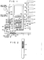
- Fig. 1 is a front view schematically showing a liquid-distributing apparatus according to the present invention;
- Fig. 2 shows a test tube containing a liquid sample, with a bar-code label put on its periphery;
- Fig. 3 is a block diagram of the control section of the apparatus;
- Fig. 4 is a perspective view of a tube-conveying mechanism;
- Fig. 5 is a cross-sectional view of the tube-conveying mechanism;
- Figs. 6 to 12 show tube holders and test tubes held by these holders;
- Fig. 13 schematically shows the sample distributor used in the apparatus;
- Fig. 14 schematically shows the member for dividing the tube holders into groups;
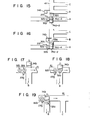
- Figs. 15 to 19 are diagrams explaining how the holders holding test tubes containing distributed quantities of the liquid sample are divided into groups;
- Fig. 20 is a side view of a tube holder of another type, which can be used in the invention; and
- Fig. 21 is a flow chart illustrating the operation of the liquid-distributing apparatus.
- One embodiment of the present invention, i.e., an apparatus for distributing a blood sample among test tubes, will now be described with reference to the accompanying drawings. As is shown in Fig. 1,
tube holders 14a to 14o holding test tubes 12a to 12o containing blood samples are transported inpath 11, one by one, towardoutlet 13 in the direction of arrow I. Fig. 2 shows one of the test tubes, i.e., test tube 16 containing a predetermined amount ofblood 15. A label is put ontest tube 12. Printed on this label is abar code 17 representing the identity ofblood sample 15 and the items for whichblood 15 will be analyzed. -
Bar code 17 is read bybar code reader 18 provided besidepath 11. The data byreader 18 is supplied to controldevice 19.Control device 19 comprisesCPU 20 andmain memory 21. The data is stored inmain memory 21 under the control ofCPU 20.Main memory 21 includes a ROM storing the program for controlling the apparatus, and a RAM for storing and providing various data items. The data output bybar code reader 18 is stored into this RAM. - Referring back to Fig. 1,
sensors 23a and 23b, and stoppers 24a and 24b are provided besidespath 11.Holders 14a to 14o, and thus tubes 12a to 12o, are transported forward inpath 11 frombar code reader 18. Stoppers 24b and 24a are actuated, stopping these tubes, group by group, each group consisting of five tubes.Holders 14a to 14o inpath 11, group by group, and first pass sensor 23b and then passsensor 23a. More specifically,holders 14a to 14e holding tubes 12a to 12e of the first group are stopped by stopper 24a in the position where the blood samples will be sucked from tubes 12a to 12e. (Hereinafter, this positions will be referred to as "sample suction position.") At this time, holders 14f to14j holding tubes 12f to 12j of the second group are stopped by stopper 24b in a first waiting position inpath 11, andholders 14k to14o holding tubes 12k to 12o of the third group are about to passbar code reader 18.Sensors 23a and 23b, which are photosensors, receive light beams emitted from two lamps provided on the other side ofpath 11 and opposing them, and convert these beams into electric signals, which will be supplied to CPU 20 (Fig. 3). In Fig. 3,sensors 23a and 23b are generally indicated atnumeral 23. - When the
first holder 14a passes sensor 23b,CPU 20 drives stopper driver (Fig. 3), whereby stopper 24a operates, thus stoppingholder 14a in the sample suction position. At the same time, the counter (not shown) provided withinCPU 20 counts one. This counter outputs a signal and is reset every time its count value reaches five. As the following fourholders driver 26. In response to this signal,stopper driver 26 drives stopper 24b, wherebyholders 14a to 14e, and thus tubes 12a to 12e of the first group, are stopped in the first waiting position. - In the meantime, as is shown in Fig. 1,
holders 33a to 33j holdingempty test tubes 32a to 32j are transported inpath 31 in the direction of arrow II. Stopper 34a stopsholders 33a to 33e, and thustubes 32a to 32e, in a sample-distributing position, and stopper 34b stops holders 33f to 33j at a second waiting position. At this time,holder 33j holdingempty tube 32j, is located beside abar code labeler 35.Labeler 35 is provided to stick a label to every test tube held beside it. On the label, a bar code has been printed bybar code printer 36 provided upstream oflabeler 35 with respect topath 31.Sensor 23c is provided besidepath 31, downstream of stopper 34b. - Two
parallel rails 38 are provided above the parallel portions ofpaths Arm 39 is movably mounted onrails 38.Sample distributor 40 is mounted on thisarm 39. The structure ofsample distributor 40 will later be described in detail. -
Holders 33a to33j holding tubes 32a to 32j, respectively, are transported frompath 31 and distributed to tube-dividinglane 41 after the blood samples contained in tubes 12a to 12e have been distributed amongtubes 32a to 32j as will be explained later. Connected to tube-dividinglane 41 are seven lanes A to G. Lane 41 and A to G, will later be described in detail. -
Path 11,holders 14a to 140, and stoppers 24a and 24bwill now be described in detail with reference to Figs. 4 to 12. - As is shown in Figs. 4 and 5,
path 11 comprisesconveyor belt 42, and two parallel,opposing side walls plate 56 connecting the lower ends ofside walls side walls Support legs walls Holes 57 are cut inside walls holders 14a to 14o, and stoppers 24a and 24b for stoppingholders 14a to 14o are mounted. -
Belt conveyor 42 comprisesbelt 58 wrapped aroundplate 56 connectingside walls 54.Belt 58 is driven bydrive source 59 such as electric motor. - Width W of
guide edges edges edges 54a and 5a and upper surface ofbelt conveyor 58 are determined in accordance with the size and shape ofholders 14a to 140. - Holders 14-a to 14o will now be described with reference to Figs. 6 to 8. As is shown in these figures, each of
holders 14a to 14o has twoannular grooves hole 52c extending in its axial direction.Hole 52c is provided to accommodatetest tube 12. The bottom ofhole 52c has asmall hole 52d. Width Gl ofannular groove 52a is slightly greater than the thickness ofguide edges guide edges annular groove 52b is slightly greater than the diameter ofstopper pin 50a of stopper 24a, which will later be descried in detail. Diameter d ofhole 52c for accommodating test tube 12a is slightly greater than the that of test tube 12a. The diameter ofhole 52d is far smaller than that of test tube 12a. Depth V ofannular grooves stopper pin 50a.Annular groove 52b can be a little deeper thanannular groove 52a. - Referring to Figs. 9 to 12, it will be explained how test tube 12a inserted in
hole 52c ofholder 14a is transported forward inpath 11.Holder 14a holding tube 12a, as is shown in Fig. 9, is set intopath 11 as is illustrated in Fig. 10. At this time, stopper 24a provided for controlling the movement ofholders 14a to 14o is in its retreated position, andstopper pin 50a is completely retreated. Asbelt 58 is driven,holder 14a is therefore moved forward, being guided byguide edges path 11. Since guide edges 54a and 55a are inserted inannular groove 52a ofholder 14a,holder 14a is stably transported, without the possibility of tipping over. When stopper 24a is actuated byCPU 20 whileholder 14a to 14o are sequentially transported inpath 11,stopper pin 50a thrusts into the gap betweenannular grooves 52a ofholders Holder 14b, located upstream ofstopper pin 50a, is thus stopped. Because ofannular grooves 52a,stopper pin 50a can thrust into the gap betweenannular grooves 52a ofholders holders adjacent holders - With reference to Fig. 13,
sample distributor 40 will be described in greater detail. When stopper 24a, which is located in the sample suction position, is driven byCPU 20,stopper pin 50a thrusts forward, wherebyholders 14a to 14e, and thus test tubes 12a to 12e held in these holders, are stopped in the first sample-distributing position. Whenholder 14e passes sensor 23b, the counter provided inCPU 20 reaches the value of five and outputs a signal. This signal is supplied fromCPU 20 toconveyor 60. In response to this signal,conveyer 60 movesarm 39 onparallel rails 38 untilarm 39 reachessensor 23d located in the sample suction position. Upon detectingarm 39,sensor 23d outputs a signal, which causes the driver to stoparm 39. As a result, sample-distributing nozzles 62a to 62e suspended fromsample distributor 40 coupled toarm 39 has their lower ends located right above test tubes 12a to 12e, respectively. - Nozzles 62a to 62e is connected to
pipes 63a to 63e held in vertical holes cut insample distributor 40.Pipes 63a to 63e are connected toair cylinder 65 provided withinarm 39, by flexible tubes 64a to 64e. - When
sample distributor 40 reaches the sample suction position,CPU 20causes conveyor 60 tolower arm 39 until the lower ends of nozzles 62a to 62e enter test tubes 12a to 12e and dip in blood sampled contained in tubes 12a to 12e. Then,CPU 20 gives a command toair cylinder 65. In response to the command,cylinder 65 makes nozzles 62a to 62e suck up predetermined quantities of blood samples, which have been determined by the data read bybar code reader 18. - Thereafter,
CPU 20 gives another command toconveyor 60. In response to this command signal,conveyor 60lifts arm 39, whereby nozzles 62a to 62e are pulled from test tubes 12a to 12e. Then,CPU 20 gives a command toconveyor 60, andconveyor 60moves sample distributor 40 onrails 38 in the horizontal direction to the sample-distribution position.Sensor 23e is provided in sample-distribution position. Whenarm 39 reaches this position,sensor 23e detectsarm 39 and produces a signal, which is supplied toconveyor 60. Upon receipt of this signal,conveyor 60 stops. As a result, the lower ends of nozzles 62a to 62e are located right abovetubes 32a to 32e already brought to the sample-distributing position. - Assume that the five blood samples contained in test tubes 12a to 12e will be distributed among
test tubes 32a to 32j, that is, each of these samples will be distributed among two tubes. In this case,CPU 20 outputs a signal toair cylinder 65. In response to this signal,cylinder 65 operates, thereby supplying blood samples from nozzles 62a to 62e intotest tubes 32a to 32e in an equal, small quantity determined by the data read bybar code reader 18 and representing the item of analysis. The quantity of every blood sample can easily be controlled by changing the distance the air cylinder is moved. After the five blood samples have been distributed amongtubes 32a to 32e,stopper pin 50a of stopper 34a is pulled out ofpath 31 under the control ofCPU 20. Hence,holders 33a to 33e, holdingtubes 32a to 32e now containing said quantities of the blood samples, are moved inpath 31 to tube-dividinglane 41. - When
holders 33a to 33e are transported to lane 41,stopper pin 50a of stopper 34b is pulled out ofpath 31 under the control ofCPU 20. Holders 33f to 33j holdingtest tubes 32f to 32j thereby move forward inpath 31 from the waiting position. When holder 33f passesdetector 23c,detector 23c outputs a signal, which is supplied toCPU 20. In response to this signal, CPU operatesstopper driver 26, wherebystopper pin 50a of stopper 34a thrusts intopath 31. As a result, holders 33f to 33j are stopped in the sample-distributing position. Then,CPU 20 outputs a signal toair cylinder 65. In response to this signal,cylinder 65 operates, whereby the blood samples, which have been sucked from test tubes 12a to 12f, are supplied from nozzles 62a to 62e intotest tubes 32f to 32j in an equal, small quantity determined by the data read bybar code reader 18 and representing the item of analysis. After the five blood samples have been distributed amongtubes 32f to 32j,stopper pin 50a of stopper 34a is retreated frompath 31 under the control ofCPU 20. Hence, holders 33f to 33j, holdingtubes 32f to 32j now containing said quantities of the blood samples, are moved inpath 31 to tube-dividinglane 41. As a result, each blood sample is distributed among two test tubes. - When
sensor 23f, which is provided at the entrance to lane 41, detectsholder 33a holding tube 32a,CPU 20 determines, from the data read bybar code reader 18, to which sorting lane, lane A, B, C, D, F or G,test tube 32a should be transported. In accordance with the decision it has made,CPU 20controls stopper driver 26, wherebydriver 26 actuates one of sorting gates 74a to 74f. Sorting gates 74a to 74f are of the same structure. As is shown in Fig. 14, each sorting gate, e.g., gate 74a, comprises drive shaft 74a-1 coupled at one end to a cylinder (not shown), plate 74a-2 secured to one end of shaft 74a-l, and strip 74a-4 extending parallel to shaft 74a-l and connected to one side of plate 74a-2. Plate 74a-2 has slanted side 74a-3, and its side connected to strip 74a-4 is shorter than the oppositing side. - With reference to Figs. 15 to 19, it will be explained how
test tubes lane 41 and then distributed to, for example, lane B and lane C, respectively. - When the
first holder 33a holdingtest tube 32a passessensor 23f as is shown in Fig. 15,CPU 20 drives sorting gate 74a, thereby transportingtest tube 32a into tube-dividinglane 41. As a result, the strip 74a-4 of gate 74a closes the entrance to laneA. Test tube 32a is therefore transported to the entrance of nextlane B. Holder 33a is pushed into the corner defined by the slanted side 74a-3 and strip 74a-4 of gate 74a, and is smoothly moved toward lane B. - At this time, the
second holder 33b holdingsecond test tube 32b is stopped by plate 74a-2 of sorting gate 74a in front of lane A. Sorting gate 74a retreats and then moves forward, whereby both first andsecond tubes - When
first holder 33a passessensor 23g as is shown in Fig. 17,CPU 20drives sorting gate 74b, thereby transportingtest tube 32a into sorting lane B as is shown in Fig. 19. At this time,second holder 33b remains stopped by sortinggate 74b in front of the entrance to lane A. When sortinggate 74b retreats,test tube 32b is transported toward next lane C. - As is shown in Fig. 6,
holders 14a-14o has twoannular grooves Holders 14a to 14o can be replaced byholders 14a', which, as is shown in Fig. 20, have threeannular grooves annular groove 52e cut in the upper portion of each holder 14', thereby to detect the presence or absence thereof. - Now, the operation of the liquid-distributing apparatus shown in Figs. 1 and 3 will be explained with reference to the flow chart of Fig. 21. First, in step Sl, an operator pushes the start button of
keyboard 81, andbar code reader 18 reads the bar codes from test tubes 12a to 12o as these tubes passreader 18 one after another. The data representing these bar codes is stored intomain memory 21. Then, in step S2,bar code printer 36 prints the bar codes represented by this data on bland labels. In step S3, the bar code labels are sticked totest tubes 32a to 32j. In the next step, step S4,air cylinder 65 sucks quantities of the blood samples from test tubes 12a to 12e as these tubes transported to sampledistributor 40. In step S5, these quantities of the blood samples are distributed, first amongtest tubes 32a to 32e and then amongtest tubes 32f to 32j. In step S6,tubes 32a to 32j are moved to tube-dividinglane 41, and are then sorted into lanes A to B. -
Test tubes 32a to 32j, containing the distributed quantities of the blood samples, are removed from lanes A to G, and are further transported to different analysis devices. If necessary, printer 82 (Fig. 3) can print the data about any distributed blood sample, which has been read frommain memory 21. The information about the blood samples, such as the blood sample numbers, the lane numbers, and the distributed quantities of the samples, can be input by operatingkeyboard 81, or can be supplied from a host computer (not shown) toCPU 20. - According to the invention, a quantity-measuring device (not shown) can be provided beside
path 11 and downstream ofbar code reader 18. This device is designed to measure the distance between it and the surface level of the blood sample in each test tube, thus determining whether or not the tube contains a sufficient amount of a sample blood. More precisely, it emits a light beam or an ultrasonic beam to the surface of the blood sample in the tube. The distance between the device and the surface level of the blood sample is measured from the time which has elapsed until the beam reaches to the device from the surface of blood sample. Sortinggate 80, identical to gates 74a to 74f in structure, is provided between the quantity-measuring device and stopper 24b as is shown in Fig. 1. When the quantity of the sample in the tube is insufficient, sortinggate 80 is operated to remove the test tube frompath 11 into discharge path lla. - In the embodiment of Fig. 1, any test tube containing a blood sample, that is set in front of
bar code reader 18, has already been opened. The tube can be opened by an automatic test tube plug extraction apparatus as is disclosed in PCT Application No. PCT/JP87/00199 filed on March 31, 1987 by the same applicant as the present application.
Claims (6)
Priority Applications (1)
| Application Number | Priority Date | Filing Date | Title |
|---|---|---|---|
| AT87106058T ATE80227T1 (en) | 1986-04-30 | 1987-04-25 | DEVICE FOR DISTRIBUTING LIQUID SAMPLES INTO TEST TUBES AND FOR DISTRIBUTING THE TEST TUBES INTO GROUPS. |
Applications Claiming Priority (10)
| Application Number | Priority Date | Filing Date | Title |
|---|---|---|---|
| JP6670786U JPS6326625U (en) | 1986-04-30 | 1986-04-30 | |
| JP1986066705U JPH0748572Y2 (en) | 1986-04-30 | 1986-04-30 | Cylindrical rack for transportation |
| JP6670686U JPS6326621U (en) | 1986-04-30 | 1986-04-30 | |
| JP66704/86 | 1986-04-30 | ||
| JP66706/86 | 1986-04-30 | ||
| JP66703/86 | 1986-04-30 | ||
| JP1986066703U JPS62179211U (en) | 1986-04-30 | 1986-04-30 | |
| JP66705/86 | 1986-04-30 | ||
| JP6670486U JPS6326623U (en) | 1986-04-30 | 1986-04-30 | |
| JP66707/86 | 1986-04-30 |
Publications (3)
| Publication Number | Publication Date |
|---|---|
| EP0243915A2 true EP0243915A2 (en) | 1987-11-04 |
| EP0243915A3 EP0243915A3 (en) | 1989-04-26 |
| EP0243915B1 EP0243915B1 (en) | 1992-09-02 |
Family
ID=27524000
Family Applications (1)
| Application Number | Title | Priority Date | Filing Date |
|---|---|---|---|
| EP87106058A Expired EP0243915B1 (en) | 1986-04-30 | 1987-04-25 | Apparatus for distributing liquid samples among test tubes and for dividing the test tubes into groups |
Country Status (9)
| Country | Link |
|---|---|
| US (1) | US4798095A (en) |
| EP (1) | EP0243915B1 (en) |
| AT (1) | ATE80227T1 (en) |
| DE (1) | DE3781451T2 (en) |
| DK (1) | DK217387A (en) |
| ES (1) | ES2005568A6 (en) |
| FI (1) | FI871895A (en) |
| GB (1) | GB2189884B (en) |
| PT (1) | PT84799B (en) |
Cited By (11)
| Publication number | Priority date | Publication date | Assignee | Title |
|---|---|---|---|---|
| EP0372755A1 (en) * | 1988-12-02 | 1990-06-13 | Bio-Tek Instruments, Inc. | Method of distinguishing among strips for different assays in an automated instrument |
| EP0403905A1 (en) * | 1989-06-19 | 1990-12-27 | F. Hoffmann-La Roche Ag | Apparatus for liquid sample aliquot distribution |
| EP0467285A2 (en) * | 1990-07-20 | 1992-01-22 | Johnson & Johnson Clinical Diagnostics, Inc. | Device for moving pipette trays in an analyzer |
| EP0619493A1 (en) * | 1993-01-29 | 1994-10-12 | Teruaki Itoh | Sample sorting apparatus |
| EP0629858A1 (en) * | 1993-06-16 | 1994-12-21 | Kabushiki Kaisha Nittec | Sample preparation apparatus |
| WO1996008433A1 (en) | 1994-09-15 | 1996-03-21 | Clids Oy | Method for marking of a vessel and a handling device for applying of the method |
| EP0809829A1 (en) * | 1995-02-16 | 1997-12-03 | Smithkline Beecham Corporation | Apparatus and process |
| WO1999028724A1 (en) * | 1997-11-27 | 1999-06-10 | A.I. Scientific Pty. Ltd. | A sample distribution apparatus/system |
| ITMI20090398A1 (en) * | 2009-03-16 | 2010-09-17 | Inpeco Ip Ltd | EQUIPMENT FOR THE MAKING OF CONTAINERS OF BIOLOGICAL MATERIAL. |
| ITTO20110963A1 (en) * | 2011-10-24 | 2012-01-23 | Giacalone Andrea | MODULAR SYSTEM FOR THE HANDLING OF LABORATORY TUBES, OR OTHERWISE. |
| EP3598141B1 (en) * | 2017-03-16 | 2022-10-19 | Hitachi High-Tech Corporation | Sample container transfer device |
Families Citing this family (34)
| Publication number | Priority date | Publication date | Assignee | Title |
|---|---|---|---|---|
| US5087423A (en) * | 1988-10-20 | 1992-02-11 | Olympus Optical Co., Ltd. | Automatic analyzing apparatus comprising a plurality of analyzing modules |
| DE3922835A1 (en) * | 1989-07-11 | 1991-01-24 | Hench Automatik App Masch | METHOD FOR MEASURING THE FLOW PROPERTIES OF FLOWABLE MEDIA |
| JP2881826B2 (en) * | 1989-07-24 | 1999-04-12 | 東ソー株式会社 | Automatic analyzer |
| US5585068A (en) * | 1990-02-20 | 1996-12-17 | Biochemical Diagnostics, Inc. | Apparatus for automatically separating a compound from a plurality of discrete liquid specimens |
| DE4018468A1 (en) * | 1990-06-08 | 1991-12-12 | Ultrakust Electronic Gmbh | METHOD AND DEVICE FOR TAKING A REPRAESENTATIVE MILK SAMPLE |
| DE4023184A1 (en) * | 1990-07-20 | 1992-01-23 | Kodak Ag | DEVICE FOR TRANSPORTING CONTAINERS WITH A LIQUID |
| AU4683593A (en) * | 1993-07-19 | 1995-02-20 | Automed Inc. | System for transporting, classifying and sorting blood specimens |
| US5849598A (en) * | 1996-03-15 | 1998-12-15 | Washington University | Method for transferring micro quantities of liquid samples to discrete locations |
| US5795784A (en) | 1996-09-19 | 1998-08-18 | Abbott Laboratories | Method of performing a process for determining an item of interest in a sample |
| US5856194A (en) | 1996-09-19 | 1999-01-05 | Abbott Laboratories | Method for determination of item of interest in a sample |
| FR2764703B1 (en) * | 1997-06-16 | 1999-08-20 | Stago Diagnostica | PROCESS FOR THE AUTOMATIC CONTINUOUS OR DISCONTINUOUS ANALYSIS OF SAMPLES CONTAINED IN CONTAINERS |
| US6024204A (en) * | 1997-11-14 | 2000-02-15 | Bayer Corporation | Conveyor system for clinical test apparatus |
| US6500609B1 (en) | 1999-02-11 | 2002-12-31 | Scynexis Chemistry & Automation, Inc. | Method and apparatus for synthesizing characterizing and assaying combinatorial libraries |
| DE19925658C2 (en) * | 1999-06-04 | 2002-04-18 | Andreas Zucker | Device for automatic sample preparation and its use |
| GB9916649D0 (en) * | 1999-07-15 | 1999-09-15 | Zeneca Ltd | Analytical sampling device |
| US6524863B1 (en) | 1999-08-04 | 2003-02-25 | Scynexis Chemistry & Automation, Inc. | High throughput HPLC method for determining Log P values |
| US6413431B1 (en) | 1999-08-10 | 2002-07-02 | Scynexis Chemistry & Automation, Inc. | HPLC method for purifying organic compounds |
| EP1212128A1 (en) | 1999-08-27 | 2002-06-12 | Scynexis Chemistry and Automation, Inc. | Sample preparation for high throughput purification |
| FI116487B (en) | 1999-11-15 | 2005-11-30 | Thermo Electron Oy | Apparatus and method for the treatment of laboratory test tubes |
| US6780648B1 (en) * | 2000-09-20 | 2004-08-24 | General Electric Company | Method and system for selectively distributing luminescence material precursors |
| JP3398361B2 (en) * | 2000-10-31 | 2003-04-21 | 照明 伊藤 | Urine collection cup loading device |
| JP3694490B2 (en) * | 2002-03-29 | 2005-09-14 | アロカ株式会社 | Sample pretreatment system |
| JP2004174350A (en) * | 2002-11-26 | 2004-06-24 | Teruaki Ito | Centrifuge loading supplementary apparatus |
| US8357538B2 (en) * | 2007-04-06 | 2013-01-22 | Qiagen Gaithersburg, Inc. | Automated assay and system |
| US8703492B2 (en) | 2007-04-06 | 2014-04-22 | Qiagen Gaithersburg, Inc. | Open platform hybrid manual-automated sample processing system |
| US9953141B2 (en) | 2009-11-18 | 2018-04-24 | Becton, Dickinson And Company | Laboratory central control unit method and system |
| EP2626707B1 (en) * | 2010-10-04 | 2019-11-06 | Hitachi High-Technologies Corporation | Sample treatment system |
| CN104040357B (en) * | 2011-11-07 | 2016-11-23 | 贝克曼考尔特公司 | Halver system and workflow |
| WO2015033023A2 (en) | 2013-09-03 | 2015-03-12 | Thermo Fisher Scientific Oy | Method and arrangement for handling test tubes |
| EP3355063B1 (en) * | 2015-09-25 | 2022-04-20 | Hitachi High-Tech Corporation | Specimen inspection automation system |
| EP3412603B1 (en) * | 2017-06-08 | 2021-07-28 | Roche Diagnostics GmbH | Switch for a conveying line for transporting a laboratory diagnostic vessel carrier |
| CN111989558A (en) * | 2018-03-16 | 2020-11-24 | 因为傲可值有限公司 | Sample processing system and method for automated processing of histological samples |
| WO2020044515A1 (en) * | 2018-08-30 | 2020-03-05 | 株式会社島津製作所 | Sample plate supply control device, sample plate supply control system, sample plate supply control method, and sample plate supply control program |
| IT202100031598A1 (en) * | 2021-12-16 | 2023-06-16 | Inpeco SA | APPARATUS AND PROCEDURE FOR THE SORTING OF BIOLOGICAL SAMPLES IN AN ANALYSIS LABORATORY |
Citations (7)
| Publication number | Priority date | Publication date | Assignee | Title |
|---|---|---|---|---|
| FR1552704A (en) * | 1967-02-08 | 1969-01-03 | Acec | Sample changer |
| FR2136453A5 (en) * | 1971-04-16 | 1972-12-22 | Siemens Ag | |
| US3854879A (en) * | 1973-07-27 | 1974-12-17 | Coulter Electronics | Sample identification and test data correlation method and apparatus |
| DE2617944B2 (en) * | 1976-04-24 | 1979-05-10 | Eppendorf Geraetebau Netheler + Hinz Gmbh, 2000 Hamburg | |
| WO1983000393A1 (en) * | 1981-07-20 | 1983-02-03 | American Hospital Supply Corp | Loading and transfer assembly for chemical analyzer |
| EP0090550A1 (en) * | 1982-03-17 | 1983-10-05 | E.I. Du Pont De Nemours And Company | Automatic chemical analysis |
| EP0264456A1 (en) * | 1986-04-30 | 1988-04-27 | Teruaki Itoh | Fully automatic apparatus for pulling out test tube stoppers |
Family Cites Families (1)
| Publication number | Priority date | Publication date | Assignee | Title |
|---|---|---|---|---|
| US4512202A (en) * | 1982-12-27 | 1985-04-23 | Beckman Instruments, Inc. | Pregrooved centrifuge tubes |
-
1987
- 1987-04-20 US US07/039,952 patent/US4798095A/en not_active Expired - Fee Related
- 1987-04-25 EP EP87106058A patent/EP0243915B1/en not_active Expired
- 1987-04-25 AT AT87106058T patent/ATE80227T1/en not_active IP Right Cessation
- 1987-04-25 DE DE8787106058T patent/DE3781451T2/en not_active Expired - Fee Related
- 1987-04-29 ES ES878701281A patent/ES2005568A6/en not_active Expired
- 1987-04-29 FI FI871895A patent/FI871895A/en not_active Application Discontinuation
- 1987-04-29 GB GB8710198A patent/GB2189884B/en not_active Expired - Lifetime
- 1987-04-29 DK DK217387A patent/DK217387A/en not_active Application Discontinuation
- 1987-04-30 PT PT84799A patent/PT84799B/en not_active IP Right Cessation
Patent Citations (7)
| Publication number | Priority date | Publication date | Assignee | Title |
|---|---|---|---|---|
| FR1552704A (en) * | 1967-02-08 | 1969-01-03 | Acec | Sample changer |
| FR2136453A5 (en) * | 1971-04-16 | 1972-12-22 | Siemens Ag | |
| US3854879A (en) * | 1973-07-27 | 1974-12-17 | Coulter Electronics | Sample identification and test data correlation method and apparatus |
| DE2617944B2 (en) * | 1976-04-24 | 1979-05-10 | Eppendorf Geraetebau Netheler + Hinz Gmbh, 2000 Hamburg | |
| WO1983000393A1 (en) * | 1981-07-20 | 1983-02-03 | American Hospital Supply Corp | Loading and transfer assembly for chemical analyzer |
| EP0090550A1 (en) * | 1982-03-17 | 1983-10-05 | E.I. Du Pont De Nemours And Company | Automatic chemical analysis |
| EP0264456A1 (en) * | 1986-04-30 | 1988-04-27 | Teruaki Itoh | Fully automatic apparatus for pulling out test tube stoppers |
Cited By (22)
| Publication number | Priority date | Publication date | Assignee | Title |
|---|---|---|---|---|
| US5439826A (en) * | 1988-12-02 | 1995-08-08 | Bio-Tek Instruments, Inc. | Method of distinguishing among strips for different assays in an automated instrument |
| EP0372755A1 (en) * | 1988-12-02 | 1990-06-13 | Bio-Tek Instruments, Inc. | Method of distinguishing among strips for different assays in an automated instrument |
| EP0403905A1 (en) * | 1989-06-19 | 1990-12-27 | F. Hoffmann-La Roche Ag | Apparatus for liquid sample aliquot distribution |
| EP0467285A2 (en) * | 1990-07-20 | 1992-01-22 | Johnson & Johnson Clinical Diagnostics, Inc. | Device for moving pipette trays in an analyzer |
| EP0467285A3 (en) * | 1990-07-20 | 1992-06-03 | Eastman Kodak Company | Device for moving pipette trays in an analyzer |
| EP0619493A1 (en) * | 1993-01-29 | 1994-10-12 | Teruaki Itoh | Sample sorting apparatus |
| US5445037A (en) * | 1993-01-29 | 1995-08-29 | Itoh; Teruaki | Sample sorting apparatus |
| EP0629858A1 (en) * | 1993-06-16 | 1994-12-21 | Kabushiki Kaisha Nittec | Sample preparation apparatus |
| AU709388B2 (en) * | 1994-09-15 | 1999-08-26 | Clids Oy | Method for marking of a vessel and a handling device for applying of the method |
| WO1996008433A1 (en) | 1994-09-15 | 1996-03-21 | Clids Oy | Method for marking of a vessel and a handling device for applying of the method |
| US6085603A (en) * | 1994-09-15 | 2000-07-11 | Clids Oy | Method for marking of a vessel and a handling device for applying of the method |
| EP0809829A4 (en) * | 1995-02-16 | 2009-07-15 | Quest Diagnostics Invest Inc | Apparatus and process |
| EP0809829A1 (en) * | 1995-02-16 | 1997-12-03 | Smithkline Beecham Corporation | Apparatus and process |
| WO1999028724A1 (en) * | 1997-11-27 | 1999-06-10 | A.I. Scientific Pty. Ltd. | A sample distribution apparatus/system |
| US6599476B1 (en) | 1997-11-27 | 2003-07-29 | A.I. Scientific Pty Ltd. | Sample distribution apparatus/system |
| US7291309B2 (en) | 1997-11-27 | 2007-11-06 | A.I. Scientific Pty Ltd. | Sample distribution apparatus/system |
| US7846384B2 (en) | 1997-11-27 | 2010-12-07 | A.I. Scientific Pty Ltd. | Sample distribution apparatus/system |
| ITMI20090398A1 (en) * | 2009-03-16 | 2010-09-17 | Inpeco Ip Ltd | EQUIPMENT FOR THE MAKING OF CONTAINERS OF BIOLOGICAL MATERIAL. |
| WO2010105992A1 (en) * | 2009-03-16 | 2010-09-23 | Inpeco Ip Ltd. | Aliquoting apparatus for biological material containers |
| US8926902B2 (en) | 2009-03-16 | 2015-01-06 | Inpeco Holding Ltd. | Aliquoting apparatus for biological material containers |
| ITTO20110963A1 (en) * | 2011-10-24 | 2012-01-23 | Giacalone Andrea | MODULAR SYSTEM FOR THE HANDLING OF LABORATORY TUBES, OR OTHERWISE. |
| EP3598141B1 (en) * | 2017-03-16 | 2022-10-19 | Hitachi High-Tech Corporation | Sample container transfer device |
Also Published As
| Publication number | Publication date |
|---|---|
| DK217387A (en) | 1987-10-31 |
| DK217387D0 (en) | 1987-04-29 |
| GB2189884B (en) | 1990-08-01 |
| FI871895A0 (en) | 1987-04-29 |
| DE3781451D1 (en) | 1992-10-08 |
| EP0243915B1 (en) | 1992-09-02 |
| ES2005568A6 (en) | 1989-03-16 |
| DE3781451T2 (en) | 1993-01-07 |
| US4798095A (en) | 1989-01-17 |
| GB8710198D0 (en) | 1987-06-03 |
| EP0243915A3 (en) | 1989-04-26 |
| FI871895A (en) | 1987-10-31 |
| GB2189884A (en) | 1987-11-04 |
| PT84799A (en) | 1987-05-01 |
| ATE80227T1 (en) | 1992-09-15 |
| PT84799B (en) | 1989-12-29 |
Similar Documents
| Publication | Publication Date | Title |
|---|---|---|
| US4798095A (en) | Apparatus for distributing liquid samples among test tubes and for dividing the test tubes into groups | |
| US5736101A (en) | Automated analytical instrument having a fluid sample holding tray transport assembly | |
| US5460778A (en) | Cutting apparatus for use in an automated analytical instrument | |
| CA1230327A (en) | Method and apparatus for transporting carriers of sealed sample tubes and mixing the samples | |
| EP0090550B1 (en) | Automatic chemical analysis | |
| EP0356250B1 (en) | Analyzers using linear sample trays with random access | |
| US4534465A (en) | Cassette for supporting test tubes of different diameters and/or lengths | |
| JP3676814B2 (en) | Apparatus and method | |
| US9446900B2 (en) | Tube sorter and tube sorting system | |
| KR20220070060A (en) | Material handling apparatus with delivery vehicles | |
| KR20150035494A (en) | Double-decker tube dispenser | |
| JPH10213586A (en) | Automatic analyzer | |
| US3587676A (en) | Apparatus for sequential treatment and analysis of samples | |
| EP0523426A2 (en) | Device for feeding objects into a waste bin of an analyzer | |
| JP2004061136A (en) | Specimen transfer apparatus | |
| KR101540554B1 (en) | Analytical system with capillary transport | |
| CN113811775B (en) | Conveying mechanism and analysis device | |
| JPH01311278A (en) | Automatic chemical analysis apparatus | |
| KR980009046A (en) | Automatic bar code labeling device for test | |
| JPH0726765U (en) | Dispensing device | |
| JPS62218870A (en) | Container conveying method in automatic analysing apparatus and its apparatus | |
| JPH064671U (en) | Sample pipe collection device of automatic pipetting device | |
| CN1030646A (en) | The device that liquor sample is distributed to test tube and test tube is divided into groups | |
| DD259689A5 (en) | DEVICE FOR DISTRIBUTING A LIQUID | |
| JPS61248857A (en) | Method and device for sorting printing plate |
Legal Events
| Date | Code | Title | Description |
|---|---|---|---|
| PUAI | Public reference made under article 153(3) epc to a published international application that has entered the european phase |
Free format text: ORIGINAL CODE: 0009012 |
|
| 17P | Request for examination filed |
Effective date: 19870704 |
|
| AK | Designated contracting states |
Kind code of ref document: A2 Designated state(s): AT BE CH DE FR IT LI LU NL SE |
|
| PUAL | Search report despatched |
Free format text: ORIGINAL CODE: 0009013 |
|
| AK | Designated contracting states |
Kind code of ref document: A3 Designated state(s): AT BE CH DE FR IT LI LU NL SE |
|
| 17Q | First examination report despatched |
Effective date: 19900824 |
|
| GRAA | (expected) grant |
Free format text: ORIGINAL CODE: 0009210 |
|
| AK | Designated contracting states |
Kind code of ref document: B1 Designated state(s): AT BE CH DE FR IT LI LU NL SE |
|
| PG25 | Lapsed in a contracting state [announced via postgrant information from national office to epo] |
Ref country code: LI Effective date: 19920902 Ref country code: CH Effective date: 19920902 |
|
| REF | Corresponds to: |
Ref document number: 80227 Country of ref document: AT Date of ref document: 19920915 Kind code of ref document: T |
|
| REF | Corresponds to: |
Ref document number: 3781451 Country of ref document: DE Date of ref document: 19921008 |
|
| ET | Fr: translation filed | ||
| ITF | It: translation for a ep patent filed | ||
| REG | Reference to a national code |
Ref country code: CH Ref legal event code: PL |
|
| PGFP | Annual fee paid to national office [announced via postgrant information from national office to epo] |
Ref country code: LU Payment date: 19930312 Year of fee payment: 7 |
|
| PGFP | Annual fee paid to national office [announced via postgrant information from national office to epo] |
Ref country code: BE Payment date: 19930318 Year of fee payment: 7 |
|
| PGFP | Annual fee paid to national office [announced via postgrant information from national office to epo] |
Ref country code: AT Payment date: 19930427 Year of fee payment: 7 |
|
| EPTA | Lu: last paid annual fee | ||
| PLBE | No opposition filed within time limit |
Free format text: ORIGINAL CODE: 0009261 |
|
| STAA | Information on the status of an ep patent application or granted ep patent |
Free format text: STATUS: NO OPPOSITION FILED WITHIN TIME LIMIT |
|
| 26N | No opposition filed | ||
| PG25 | Lapsed in a contracting state [announced via postgrant information from national office to epo] |
Ref country code: LU Free format text: LAPSE BECAUSE OF NON-PAYMENT OF DUE FEES Effective date: 19940425 Ref country code: AT Effective date: 19940425 |
|
| PG25 | Lapsed in a contracting state [announced via postgrant information from national office to epo] |
Ref country code: BE Effective date: 19940430 |
|
| BERE | Be: lapsed |
Owner name: ITOH TERUAKI Effective date: 19940430 |
|
| EAL | Se: european patent in force in sweden |
Ref document number: 87106058.8 |
|
| PGFP | Annual fee paid to national office [announced via postgrant information from national office to epo] |
Ref country code: FR Payment date: 19970410 Year of fee payment: 11 |
|
| PGFP | Annual fee paid to national office [announced via postgrant information from national office to epo] |
Ref country code: SE Payment date: 19970416 Year of fee payment: 11 |
|
| PGFP | Annual fee paid to national office [announced via postgrant information from national office to epo] |
Ref country code: DE Payment date: 19970421 Year of fee payment: 11 |
|
| PGFP | Annual fee paid to national office [announced via postgrant information from national office to epo] |
Ref country code: NL Payment date: 19970428 Year of fee payment: 11 |
|
| PG25 | Lapsed in a contracting state [announced via postgrant information from national office to epo] |
Ref country code: SE Free format text: LAPSE BECAUSE OF NON-PAYMENT OF DUE FEES Effective date: 19980426 |
|
| PG25 | Lapsed in a contracting state [announced via postgrant information from national office to epo] |
Ref country code: FR Free format text: THE PATENT HAS BEEN ANNULLED BY A DECISION OF A NATIONAL AUTHORITY Effective date: 19980430 |
|
| PG25 | Lapsed in a contracting state [announced via postgrant information from national office to epo] |
Ref country code: NL Free format text: LAPSE BECAUSE OF NON-PAYMENT OF DUE FEES Effective date: 19981101 |
|
| NLV4 | Nl: lapsed or anulled due to non-payment of the annual fee |
Effective date: 19981101 |
|
| EUG | Se: european patent has lapsed |
Ref document number: 87106058.8 |
|
| PG25 | Lapsed in a contracting state [announced via postgrant information from national office to epo] |
Ref country code: DE Free format text: LAPSE BECAUSE OF NON-PAYMENT OF DUE FEES Effective date: 19990202 |
|
| REG | Reference to a national code |
Ref country code: FR Ref legal event code: ST |
|
| PG25 | Lapsed in a contracting state [announced via postgrant information from national office to epo] |
Ref country code: IT Free format text: LAPSE BECAUSE OF NON-PAYMENT OF DUE FEES Effective date: 20050425 |