EP0243837B1 - Method and device for treating printed products such as newspapers, magazines and the like - Google Patents
Method and device for treating printed products such as newspapers, magazines and the like Download PDFInfo
- Publication number
- EP0243837B1 EP0243837B1 EP87105782A EP87105782A EP0243837B1 EP 0243837 B1 EP0243837 B1 EP 0243837B1 EP 87105782 A EP87105782 A EP 87105782A EP 87105782 A EP87105782 A EP 87105782A EP 0243837 B1 EP0243837 B1 EP 0243837B1
- Authority
- EP
- European Patent Office
- Prior art keywords
- winding
- roll
- tape
- drive
- storage unit
- Prior art date
- Legal status (The legal status is an assumption and is not a legal conclusion. Google has not performed a legal analysis and makes no representation as to the accuracy of the status listed.)
- Expired
Links
Images


Classifications
-
- B—PERFORMING OPERATIONS; TRANSPORTING
- B65—CONVEYING; PACKING; STORING; HANDLING THIN OR FILAMENTARY MATERIAL
- B65H—HANDLING THIN OR FILAMENTARY MATERIAL, e.g. SHEETS, WEBS, CABLES
- B65H29/00—Delivering or advancing articles from machines; Advancing articles to or into piles
- B65H29/006—Winding articles into rolls
-
- B—PERFORMING OPERATIONS; TRANSPORTING
- B65—CONVEYING; PACKING; STORING; HANDLING THIN OR FILAMENTARY MATERIAL
- B65H—HANDLING THIN OR FILAMENTARY MATERIAL, e.g. SHEETS, WEBS, CABLES
- B65H2301/00—Handling processes for sheets or webs
- B65H2301/40—Type of handling process
- B65H2301/41—Winding, unwinding
- B65H2301/419—Winding, unwinding from or to storage, i.e. the storage integrating winding or unwinding means
- B65H2301/4192—Winding, unwinding from or to storage, i.e. the storage integrating winding or unwinding means for handling articles of limited length in shingled formation
- B65H2301/41922—Winding, unwinding from or to storage, i.e. the storage integrating winding or unwinding means for handling articles of limited length in shingled formation and wound together with single belt like members
-
- B—PERFORMING OPERATIONS; TRANSPORTING
- B65—CONVEYING; PACKING; STORING; HANDLING THIN OR FILAMENTARY MATERIAL
- B65H—HANDLING THIN OR FILAMENTARY MATERIAL, e.g. SHEETS, WEBS, CABLES
- B65H2701/00—Handled material; Storage means
- B65H2701/10—Handled articles or webs
- B65H2701/19—Specific article or web
- B65H2701/1932—Signatures, folded printed matter, newspapers or parts thereof and books
Definitions
- the present invention relates to a device for processing printed products, such as newspapers, magazines and the like, particularly in scale formation, according to the preamble of claim I, and to a mobile storage unit for use in such a device.
- both the winding core and the winding tape reel are arranged fixedly in the transportable frame (DE-OS 32 36 866 or the corresponding GB-PS 2107 681 and EP-OS 0 135 080 or the corresponding US-PS 4,523,751).
- Each frame has coupling devices for coupling the winding core and the reel to a drive unit arranged in the stationary winding station.
- Movable frames are now known from EP-OS 0 149 058 which are loaded outside of an unwinding station with a full reel which is made ready for unwinding. A frame together with the winding is then moved into an unwinding station, in which a coupling to a drive arranged in the unwinding station takes place.
- the frame In addition to the storage for a winding and a winding tape reel, the frame also provides a path for the printed products unwound from the winding.
- this also makes the construction complex.
- the structure of these racks is not suitable for winding printed products into a winding.
- the present invention is based on the object of creating a device of the type mentioned at the outset which offers a wide range of possible uses with the smallest possible number of mobile storage units.
- the storage units suitable for use in such a device are distinguished by the features listed in the characterizing part of claim 12.
- the mobile storage units do not necessarily have to remain with the reels in an intermediate store. Rather, it is possible to continue using the storage units to form new windings while the finished windings are temporarily stored.
- the storage units can thus be used continuously and do not have to remain blocked in interim storage facilities.
- a particularly simple construction of the storage unit is obtained if both the winding core or the winding as well as the tape reel are driven on their circumference. In such an embodiment, it is not necessary to provide a coupling arrangement on the storage unit itself for coupling the winding core and the tape reel to a drive which is arranged in the winding station.
- winding core or the winding and the reel are expediently driven in the manner described in the dependent claims 5 to 7.
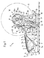
- winding station has a fixed frame 2 in which a rocker 3 is mounted, which is pivotable at one end about the axis designated 3a.
- a belt conveyor 4 is arranged in this rocker 3 and is driven in the direction of arrow A by a drive motor 5 accommodated in the frame 2.
- the corresponding drive connection is designated 6.
- a cylinder-piston unit 7 engages on the rocker 3 and can be pivoted about the axis 7a at the other end is stored in frame 2.
- the rocker 3 is preceded by a belt conveyor 8 which is driven in the direction of arrow B in a manner not shown. Through this belt conveyor 8, the print products 9 accumulating in scale formation S are fed and transferred to the belt conveyor 4.
- each printed product 9 lies on the leading printed product in the scale formation S, so that the leading edges 9a, which in the present case are the folded edges, lie on top of the scale formation S.
- the winding station I also includes two drive assemblies 10 and 11.
- the drive assembly 10 the structure of which can be seen in FIG. 5, has a swivel frame 12 which is mounted in the rocker 3 so as to be pivotable about the axis 12a.
- the swivel frame 12 has two arms 13 and 14 arranged on the side of the belt conveyor 4, which carry a shaft 15 at their free end (FIG. 5).
- a drive roller 16 designed as a friction wheel is seated on this shaft 15.
- a pin 17 projects laterally from the arm 14, on which a cylinder-piston unit 18 engages. The latter is pivotally mounted on the rocker 3 about the axis 18a.
- the shaft 15 is connected to a sprocket 19 which is connected via a chain 20 to a sprocket 21 rotatably mounted on the rocker 3.
- the sprocket 21 is driven by the drive motor 5 via the drive connection 22, which is only shown schematically.
- the other drive arrangement II is constructed similarly to the drive arrangement 10 and also has a swivel frame 23 which is mounted in the frame 2 so as to be pivotable about the axis 23a.
- This swivel frame 23 has a shaft 24 on which a drive roller 25, which is also designed as a friction wheel, is seated.
- a cylinder-piston unit 26 acts on the frame 23 and is arranged in the frame 2 so as to be pivotable about the axis 26a.
- the shaft 24 and thus also the drive roller 25 are also driven by the drive motor 5.
- the relevant, only schematically indicated drive connection is designated by 27.
- a mobile storage unit 28 is located in the winding station I, the exact structure of which can be seen in FIGS. 2-6.
- This storage unit 28 has a transportable frame 29 which is provided with feet 30 which are attached to the underside of a base plate 31.
- an upright, essentially vertical support 32 which is formed by two supports 33 and 34 which form an acute angle with one another.
- a shaft 35 is connected to it, which projects from the support 32 and extends essentially in the horizontal direction.
- a sleeve 36 is rotatably mounted on the shaft 35. On this sleeve 36 three radially projecting support arms 37, 38 and 39 are attached. One of these support arms 39 is provided with a retractable and extendable support 40.
- the carrier 33 there is an opening 41 in which a tape reel 42 for a winding tape 43 is accommodated.
- the tape reel 42 With its spool core 44, the tape reel 42 is seated on a bearing pin 45 which passes through the opening 41 and which is removably mounted in the carrier 33.
- Deflection rollers 46, 47, 48 and 49 are rotatably mounted on the carrier 33 and on the base plate 31, over which the winding tape 43 is guided.
- the latter runs from the reel 42 to a hollow cylindrical winding core 50 which is designed as a sleeve and is held by the support arms 37, 38, 39. The latter attack the inside of the winding core 50.
- the tape reel 42 is laterally offset with respect to the winding core 50.
- this winding tape section 43a is brought into a position in which it can be aligned with the center of the winding core 50, as shown in FIGS 3 and 5 is readily apparent.
- an empty winding core 50 is placed on the support arms 37, 38, 39.
- the support 40 is retracted, the empty winding core 50 is placed on the other two support arms 37 and 38 and then the support 40 is extended until the winding core 50 is tensioned by the support arms 37, 38, 39 and rotates with the sleeve 36 can.
- a full reel 42 is inserted into the opening 41, which is freely rotatable on the bearing pin 45.
- the winding tape 43 is then guided over the deflection rollers 46, 47, 48 and 49 and connected to the winding core 50.
- the drive rollers 16 and 25 are pivoted by actuating the cylinder-piston units 18 and 26 until they rest on the circumference 50a of the winding core 50 or on the circumference 42a of the winding tape reel 42.
- the drive roller 16 of the drive arrangement 10 comes to rest on the outermost turn of the winding tape 43 which has already been wound onto the winding core 50, as shown in FIG. 5.
- the motor 5 now drives the belt conveyor 4 on the one hand and the drive rollers 16 and 25 on the other hand, in the direction D (drive roller 16) or in the direction E (drive roller 25).
- the tape reel 42 is driven by the drive arrangement II at a peripheral speed which is somewhat is smaller than the peripheral speed of the winding core 50 or the winding W.
- the conveying speed of the belt conveyor 4 corresponds approximately to the peripheral speed of the winding core 50 or the winding W. The latter is somewhat constricted in the region of the winding belt 43. Since, as already mentioned, the drive roller 16 engages the outermost turn of the wound winding tape 43, the winding W is driven at a distance from the axis of rotation 35a of the winding W that is somewhat smaller than the radius of the winding outside the area of the winding tape 43 .
- the two drive rollers 16 and 25 are driven by one and the same drive motor 5.
- the latter also drives the belt conveyor 4.
- the drive connections 22 and 27 between the motor 5 and the drive rollers 16 and 25 contain no slip clutches, winder gear and the like.
- the winding tape 43 is looped around the finished winding a few more times.
- the drive rollers 16 and 25 are lifted again by means of the cylinder-piston units 18 and 26 from the circumference U of the winding W or from the circumference 42a of the tape reel 42.
- the storage unit 28 is then removed from the winding station I and replaced by a new storage unit 28 prepared in the manner described, on the winding core 50 of which printed products 9 are then wound again.
- the support 40 is now retracted and the winding core 50 together with the winding W is thus released from the driving connection with the supporting arms 37, 38, 39.
- the tape reel 42 is released for removal from the opening 41.
- the winding core 50 together with the tape reel 42 containing the remaining length of winding tape are now removed from the frame 29 and placed in an intermediate store. If the entire winding tape 43 has been wound up, the empty spool core 44 can be used separately from the winding W for further use.
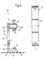
- FIG. 6 shows the storage unit 28 after the winding W and the winding tape reel 42 have been removed.
- the storage unit 28 is now ready for a new use, e.g. for receiving an empty winding core 50 and a full reel 42 in order to be used for the formation of a new winding.
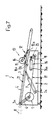
- FIG. 7 shows the take-up station 1 in its inoperative position, in which no storage unit 28 is coupled.
- the cylinder-piston units 7, 18 and 26 are in the retracted state.
- the same reference numerals are used for the individual components as in FIG. 1.
- An unwinding station 51 which is shown in FIG. 8, is provided for unwinding the printed products 9 from the reels W.
- This unwinding station 51 is very similar in structure to the winding station I and also has a stationary frame 52 in which a rocker 53 is pivotally mounted about an axis 53a.
- a belt conveyor 54 runs in this rocker 53 and is driven in the direction of arrow H by a drive motor 55 accommodated in the frame 52.
- the corresponding drive connection is designated 56.
- a cylinder-piston unit 57 engages on the rocker 53 and is mounted in the frame 52 so that it can pivot about the axis 57a.
- Downstream of the rocker 53 is a belt conveyor 58, the conveying direction of which is designated I.
- the drive arrangement 59 thus has a swivel frame 61 which is mounted in the rocker 53 so as to be pivotable about the axis 61a.
- This swivel frame 61 has a shaft 62 on which a drive roller 63 designed as a friction wheel is seated.
- a cylinder-piston unit 64 engages on the frame 61 and is fastened to the rocker 53 so that it can pivot about the axis 64a.
- the drive roller 63 is driven by the motor 55 via a drive connection 65 which is only shown schematically.
- the other drive arrangement 60 also has a swivel frame 66 which is mounted in the frame 52 so as to be pivotable about the axis 66a.
- the swivel frame 66 has a shaft 67 on which a drive roller 68 designed as a friction wheel is seated.
- a cylinder-piston unit 69 engages on the swivel frame 66 and is mounted in the frame 52 so as to be pivotable about the axis 69a.
- the drive roller 68 is driven by the motor 55 via the drive connection, shown only schematically, designated 70.
- the drive rollers 63 and 68 are driven in comparison to the drive rollers 16 and 25 of the winding station I in the opposite direction, namely in the direction of arrow K (drive roller 63) and arrow L (drive roller 68). These drive rollers 63, 68 also engage on the circumference U of the winding or on the circumference 42a of the tape reel 42. This means that the reel is rotated in the direction of arrow M and the reel 42 in the direction of arrow N.
- the drive roller 63 acts on the outermost turn of the winding tape 43 wound on the winding W.
- the drive of the winding W and the reel 42 takes place essentially the same as described on the basis of the winding process. However, the winding W is driven at a peripheral speed which is slightly lower than the peripheral speed of the tape reel 42 in order to keep the winding tape 43 taut during the unwinding process.
- the latter is inserted into an empty storage unit 28.
- the winding core 50 is placed on the support arms 37 and 38, whereupon the support 40 is extended and the winding core 50 is tensioned.
- the free end of the winding tape is then connected to a coil core 44 placed on the bearing pin 45.
- the storage unit 28 is thus ready for the unwinding process.
- the storage unit 28 prepared in this way is brought into the unwinding station 51, whereupon the drive rollers 63 and 68 are applied to the reel W or the reel 42.
- the band Spool 42 By driving the band Spool 42, the winding tape 43 is unwound from the winding W, at the same time the scale formation S is also unwound and carried away by the belt conveyor 54 and transferred to the belt conveyor 58.
- each printed product 9 no longer rests on the previous, but on the following printed product. This means that the leading edges 9a before winding up now form the trailing edges.
- the now emptied storage unit 28 is removed from the unwinding station 51 and replaced by a loaded storage unit 28 which is emptied in the manner described.
- the emptied storage unit 28 can now be brought directly to a winding station I, since it is basically ready for winding printed products. However, it is also possible to remove the empty winding core 50 and the full reel 42 and to load the storage unit 28 again with a full reel W and an empty reel core 44 or the reel 42 belonging to this reel W.
- the mobile storage units 28 are simple in construction, since only bearings 35 to 40 and 45 have to be provided for the removable storage of the winding cores 50 or the tape reels 42 and deflection rollers 46 to 49.
- the fact that the tape reel 42 is accommodated in the carrier 33 further contributes to the simple construction. A separate support for storing the reel 42 can thus be saved.
- the storage units 28 can be used continuously since the windings W and the reels 42 can be removed and the storage units 28 therefore do not necessarily have to remain blocked in an intermediate store.
- the drive arrangements 10, II and 59, 60 can be very simple. Slip clutches, winder gears and the like are not necessary.
Abstract
Description
Die vorliegende Erfindung betrifft eine Vorrichtung zum Verarbeiten von insbesondere in Schuppenformation anfallenden Druckereierzeugnissen, wie Zeitungen, Zeitschriften und dergleichen, gemäss Oberbegriff des Anspruches I sowie eine mobile Speichereinheit zur Verwendung in einer solchen Vorrichtung.The present invention relates to a device for processing printed products, such as newspapers, magazines and the like, particularly in scale formation, according to the preamble of claim I, and to a mobile storage unit for use in such a device.
Bei bekannten Vorrichtungen dieser Art ist sowohl der Wikkelkern wie auch die Wickelbandspule fest im transportablen Gestell angeordnet (DE-OS 32 36 866 bzw. die dieser inhaltlich entsprechende GB-PS 2107 681 und EP-OS 0 135 080 bzw. die entsprechende US-PS 4,523,751). Jedes Gestell weist Kopplungseinrichtungen zum Koppeln des Wickelkernes und der Bandspule mit einer in der stationären Aufwickelstation angeordneten Antriebseinheit auf.In known devices of this type, both the winding core and the winding tape reel are arranged fixedly in the transportable frame (DE-OS 32 36 866 or the corresponding GB-PS 2107 681 and EP-OS 0 135 080 or the corresponding US-PS 4,523,751). Each frame has coupling devices for coupling the winding core and the reel to a drive unit arranged in the stationary winding station.
Diese bekannten mobilen Speichereinheiten sind nun konstruktiv aufwendig und daher in der Anschaffung verhältnismässig teuer. Das bedeutet, dass seitens der Druckereibetriebe eine beträchtliche Investition erforderlich ist, wird doch eine grosse Anzahl solcher Speichereinheiten benötigt. Hiezu trägt auch der Umstand bei, dass bei einer Zwischenlagerung der Wickel die zugeordnete Speichereinheit ebenfalls im Zwischenlager verbleiben muss und daher für einen weiteren Einsatz nicht zur Verfügung steht.These known mobile storage units are now structurally complex and therefore relatively expensive to purchase. This means that a considerable investment is required on the part of the printing companies, since a large number of such storage units is required. The fact that the associated storage unit must also remain in the intermediate storage when the winding is temporarily stored also contributes to this and is therefore not available for further use.
In der bereits erwähnten EP-OS 0 135 080 (bzw. der entsprechenden US-PS 4,523,751) wird zwar eine Ausführungsform vorgeschlagen, bei der der Wickelkern bzw. der sich auf diesem bildende Wickel am Umfang angetrieben wird. Dies bedeutet zwar, dass die Speichereinheit nicht mit einer Kopplungsanordnung zum Koppeln des Wickelkernes mit dem stationären Antrieb versehen werden muss, doch sind im übrigen auch bei einer solchen Variante die vorstehend dargelegten Nachteile vorhanden.In the already mentioned EP-OS 0 135 080 (or the corresponding US Pat. No. 4,523,751) an embodiment is proposed in which the winding core or the winding forming on it is driven on the circumference. Although this means that the storage unit does not have to be provided with a coupling arrangement for coupling the winding core to the stationary drive, the disadvantages set out above also exist in such a variant.
Aus der EP-OS 0 149 058 sind nun verfahrbare Gestelle bekannt, die ausserhalb einer Abwickelstation mit einem vollen Wickel beladen werden, der zum Abwickeln bereit gemacht wird. Anschliessend wird jeweils ein Gestell mitsamt dem Wickel in eine Abwickelstation gefahren, in der ein Ankoppeln an einen in der Abwickelstation angeordneten Antrieb erfolgt. Im Gestell ist neben der Lagerung für einen Wickel und eine Wickelbandspule noch eine Wegführung für die vom Wickel abgewickelten Druckereierzeugnisse vorgesehen. Dies macht die Konstruktion jedoch ebenfalls aufwendig. Im übrigen sind diese Gestelle von ihrem Aufbau her nicht zum Aufwickeln von Druckprodukten zu einem Wikkel geeignet.Movable frames are now known from EP-OS 0 149 058 which are loaded outside of an unwinding station with a full reel which is made ready for unwinding. A frame together with the winding is then moved into an unwinding station, in which a coupling to a drive arranged in the unwinding station takes place. In addition to the storage for a winding and a winding tape reel, the frame also provides a path for the printed products unwound from the winding. However, this also makes the construction complex. In addition, the structure of these racks is not suitable for winding printed products into a winding.
Der vorliegenden Erfindung liegt nun die Aufgabe zugrunde, eine Vorrichtung der eingangs genannten Art zu schaffen, die mit einer möglichst geringen Anzahl von mobilen Speichereinheiten vielseitige Einsatzmöglichkeiten bietet.The present invention is based on the object of creating a device of the type mentioned at the outset which offers a wide range of possible uses with the smallest possible number of mobile storage units.
Diese Aufgabe wird erfindungsgemäss durch die Merkmale des kennzeichnenden Teiles des Anspruches I gelöst.This object is achieved according to the invention by the features of the characterizing part of claim I.
Die zur Verwendung in einer solchen Vorrichtung geeigneten Speichereinheiten zeichnen sich durch die im kennzeichnenden Teil des Anspruches 12 aufgeführten Merkmale aus.The storage units suitable for use in such a device are distinguished by the features listed in the characterizing part of
Da die Möglichkeit gegeben ist, den Wickel und auch die Bandspule aus dem Gestell zu entfernen, müssen die mobilen Speichereinheiten nicht zwingend mit den Wickeln in einem Zwischenlager verbleiben. Vielmehr ist es möglich, die Speichereinheiten weiter zur Bildung von neuen Wickeln zu verwenden, während die fertigen Wickel zwischengelagert werden. Die Speichereinheiten können somit dauernd verwendet werden und müssen nicht in Zwischenlagern blockiert bleiben.Since it is possible to remove the reel and the reel from the frame, the mobile storage units do not necessarily have to remain with the reels in an intermediate store. Rather, it is possible to continue using the storage units to form new windings while the finished windings are temporarily stored. The storage units can thus be used continuously and do not have to remain blocked in interim storage facilities.
Eine besonders einfache Konstruktion der Speichereinheit ergibt sich dann, wenn sowohl der Wickelkern bzw. der Wikkel wie auch die Bandspule an ihrem Umfang angetrieben werden. Bei einer solchen Ausführungsform ist es nicht erforderlich, an der Speichereinheit selber eine Kupplungsanordnung zum Koppeln von Wickelkern und Bandspule mit einem Antrieb, der in der Aufwickelstation angeordnet ist, vorzusehen.A particularly simple construction of the storage unit is obtained if both the winding core or the winding as well as the tape reel are driven on their circumference. In such an embodiment, it is not necessary to provide a coupling arrangement on the storage unit itself for coupling the winding core and the tape reel to a drive which is arranged in the winding station.
Der Antrieb des Wickelkernes bzw. des Wickels und der Bandspule erfolgt zweckmässigerweise auf die in den abhängigen Ansprüchen 5 bis 7 umschriebene Art.The winding core or the winding and the reel are expediently driven in the manner described in the
Das Abwickeln der Druckereierzeugnisse von den Wickeln erfolgt in einer Abwickelstation, die der Aufwickelstation sehr ähnlich ist. Eine bevorzugte Ausgestaltung einer solchen Abwickelstation bildet Gegenstand der abhängigen Ansprüche 8 bis II.The unwinding of the printed products from the reels takes place in an unwinding station which is very similar to the rewinding station. A preferred embodiment of such an unwinding station forms the subject of
Im folgenden wird anhand der Zeichnung ein Ausführungsbeispiel des Erfindungsgegenstandes näher erläutert. Es zeigt rein schematisch:
- Fig. I Eine Aufwickelstation mit mobiler Speichereinheit in Seitenansicht,
- Fig. 2 In Seitenansicht die mobile Speichereinheit,
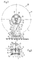
- Fig. 3 Die mobile Speichereinheit in Vorderansicht und teilweise im Schnitt,
- Fig. 4 Einen Schnitt entlang der Linie IV - IV in Fig. 3,
- Fig. 5 Einen Schnitt etwa entlang der Linie V - V in Fig. 1,
- Fig. 6 In einer der Fig. 3 entsprechenden Darstellung eine mobile Speichereinheit mit entferntem Wikkel und entfernter Bandspule,
- Fig. 7 Eine Aufwickelstation in Ausserbetriebstellung ohne angekoppelte mobile Speichereinheit, und
- Fig. 8 In Seitenansicht eine Abwickelstation.
- I a winding station with a mobile storage unit in side view,
- 2 is a side view of the mobile storage unit,
- 3 The mobile storage unit in front view and partly in section,
- 4 shows a section along the line IV-IV in FIG. 3,
- 5 shows a section approximately along the line V - V in FIG. 1,
- 6 shows a representation corresponding to FIG. 3, a mobile storage unit with the winding and the reel removed,
- Fig. 7 A take-up station in the non-operating position without a connected mobile storage unit, and
- Fig. 8 A side view of an unwinding station.
Die in Fig. I in Seitenansicht und nur rein schematisch dargestellte Aufwickelstation weist einen ortsfesten Rahmen 2 auf, in welchem eine Wippe 3 gelagert ist, die am einen Ende um die mit 3a bezeichnete Achse schwenkbar ist. In dieser Wippe 3 ist ein Bandförderer 4 angeordnet, der von einem im Rahmen 2 untergebrachten Antriebsmotor 5 in Richtung des Pfeiles A angetrieben wird. Die entsprechende Antriebsverbindung ist mit 6 bezeichnet. An der Wippe 3 greift eine Zylinder-Kolbeneinheit 7 an, welche am andern Ende um die Achse 7a schwenkbar im Rahmen 2 gelagert ist. Der Wippe 3 ist ein Bandförderer 8 vorgeschaltet, der auf nicht näher dargestellte Weise in Richtung des Pfeiles B angetrieben wird. Durch diesen Bandförderer 8 werden die in Schuppenformation S anfallenden Druckprodukte 9 zugeführt und dem Bandförderer 4 übergeben. Wie aus Fig. I hervorgeht, liegt in der Schuppenformation S jeweils jedes Druckprodukt 9 auf dem vorauslaufenden Druckprodukt auf, so dass die vorlaufenden Kanten 9a, welche im vorliegenden Fall die Falzkanten sind, in der Schuppenformation S oben liegen.I in side view and only purely schematically shown winding station has a
Zur Aufwickelstation I gehören weiter zwei Antriebsanordnungen 10 und 11. Die Antriebsanordnung 10, deren Aufbau aus Fig. 5 ersichtlich ist, weist einen Schwenkrahmen 12 auf, der um die Achse 12a schwenkbar in der Wippe 3 gelagert ist. Der Schwenkrahmen 12 weist zwei seitlich des Bandförderers 4 angeordnete Arme 13 und 14 auf, die an ihrem freien Ende eine Welle 15 tragen (Fig. 5). Auf dieser Welle 15 sitzt eine als Reibrad ausgebildete Antriebsrolle 16. Mit der Welle 15 fluchtend steht seitlich vom Arm 14 ein Bolzen 17 ab, an dem eine Zylinder-Kolbeneinheit 18 angreift. Letztere ist um die Achse 18a schwenkbar an der Wippe 3 gelagert. Auf der dem Bolzen 17 gegenüberliegenden Seite ist die Welle 15 mit einem Kettenrad 19 verbunden, das über eine Kette 20 mit einem an der Wippe 3 drehbar gelagerten Kettenrad 21 in Antriebsverbindung steht. Das Kettenrad 21 wird vom Antriebsmotor 5 her über die nur schematisch dargestellte Antriebsverbindung 22 angetrieben.The winding station I also includes two
Die andere Antriebsanordnung II ist ähnlich aufgebaut wie die Antriebsanordnung 10 und weist ebenfalls einen Schwenkrahmen 23 auf, der um die Achse 23a schwenkbar im Rahmen 2 gelagert ist. Dieser Schwenkrahmen 23 weist eine Welle 24 auf, auf der eine ebenfalls als Reibrad ausgebildete Antriebsrolle 25 sitzt. Am Rahmen 23 greift eine Zylinder-Kolbeneinheit 26 an, die um die Achse 26a schwenkbar im Rahmen 2 angeordnet ist. Die Welle 24 und somit auch die Antriebsrolle 25 werden ebenfalls vom Antriebsmotor 5 her angetrieben. Die diesbezügliche, nur schematisch angedeutete Antriebsverbindung ist mit 27 bezeichnet.The other drive arrangement II is constructed similarly to the
In der Aufwickelstation I befindet sich eine mobile Speichereinheit 28, deren genauer Aufbau aus den Fig. 2 - 6 ersichtlich ist. Diese Speichereinheit 28 weist ein transportierbares Gestell 29 auf, das mit Füssen 30 versehen ist, die an der Unterseite einer Grundplatte 31 an dieser angebracht sind. Mit dieser Grundplatte 31 ist ferner eine aufrechtstehende, im wesentlichen vertikale Stütze 32 verbunden, welche durch zwei miteinander einen spitzen Winkel einschliessende Träger 33 und 34 gebildet ist. Am oberen Ende dieser Stütze 32 ist mit dieser eine Welle 35 verbunden, die von der Stütze 32 sich im wesentlichen in horizontaler Richtung erstreckend absteht. Auf der Welle 35 ist drehbar eine Hülse 36 gelagert. An dieser Hülse 36 sind drei radial abstehende Stützarme 37, 38 und 39 befestigt. Einer dieser Stützarme 39 ist mit einer ein-und ausfahrbaren Stütze 40 versehen.A
Im Träger 33 ist eine Oeffnung 41 vorhanden, in der eine Bandspule 42 für ein Wickelband 43 untergebracht ist. Mit ihrem Spulenkem 44 sitzt die Bandspule 42 auf einem Lagerbolzen 45, der die Oeffnung 41 durchsetzt und der herausziehbar im Träger 33 gelagert ist. Am Träger 33 und an der Grundplatte 31 sind Umlenkrollen 46, 47, 48 und 49 drehbar gelagert, über die das Wickelband 43 geführt ist. Letzteres verläuft von der Bandspule 42 zu einem als Hülse ausgebildeten, hohlzylindrischen Wickelkern 50, der durch die Stützarme 37, 38, 39 gehalten ist. Letztere greifen an der Innenseite des Wickelkernes 50 an.In the
Wie insbesondere aus Fig. 3 hervorgeht, ist die Bandspule 42 gegenüber dem Wickelkern 50 seitlich versetzt. Durch Umlenkung des Wickelbandabschnittes 43a zwischen Bandspule 42 und Wickelkern 50 mittels der Umlenkrollen 46, 47, 48, 49 wird dieser Wickelbandabschnitt 43a in eine Lage gebracht, in der er etwa auf die Mitte des Wickelkernes 50 ausgerichtet auf diesen auflaufen kann, wie das aus den Fig. 3 und 5 ohne weiteres ersichtlich ist.3, the
Bevor eine Speichereinheit 28 in die Aufwickelstation I eingesetzt wird, wird auf die Stützarme 37, 38, 39 ein leerer Wickelkern 50 aufgesetzt. Zu diesem Zwecke wird die Stütze 40 eingefahren, der leere Wickelkern 50 auf die beiden andern Stützarme 37 und 38 aufgelegt und dann die Stütze 40 soweit ausgefahren, bis der Wickelkern 50 durch die Stützarme 37, 38, 39 verspannt ist und mit der Hülse 36 mitdrehen kann. Im weitern wird in die Oeffnung 41 eine volle Bandspule 42 eingesetzt, die frei drehbar auf dem Lagerbolzen 45 sitzt. Anschliessend wird das Wickelband 43 über die Umlenkrollen 46, 47, 48 und 49 geführt und mit dem Wickelkern 50 verbunden.Before a
Befindet sich die so vorbereitete Speichereinheit 28 in der Aufwickelstation I, so werden durch Betätigen der Zylinder-Kolbeneinheiten 18 und 26 die Antriebsrollen 16 und 25 verschwenkt, bis sie am Umfang 50a des Wickelkernes 50 bzw. am Umfang 42a der Wickelbandspule 42 anliegen. Dabei kommt die Antriebsrolle 16 der Antriebsanordnung 10 auf der äussersten Windung des bereits auf den Wickelkern 50 aufgewickelten Wickelbandes 43 zur Auflage, wie das Fig. 5 zeigt. Durch den Motor 5 werden nun einerseits der Bandförderer 4 und anderseits die Antriebsrollen 16 und 25 angetrieben, und zwar in Richtung D (Antriebsrolle 16) bzw. in Richtung E (Antriebsrolle 25). Die Drehbewegung der Antriebsrollen 16 und 25 hat infolge des Reibschlusses mit dem Wickelband 43 bzw. der Bandspule 42 zur Folge, dass der Wickelkern 50 in Richtung des Pfeiles F und die Wikkelbandspule 42 in Richtung des Pfeiles G gedreht wird. Die durch den Bandförderer 4 zugeführte Schuppenformation S wird dabei zusammen mit dem Wickelband 43 auf den Wikkelkem 50 aufgewickelt. Dieser Aufwickelvorgang erfolgt grundsätzlich gleich wie in der CH-PS 642 602 bzw. der entsprechenden US-PS 4,438,618 beschrieben.If the
Damit das Wickelband 43 unter Zugspannung stehend auf den Wickelkern 50 bzw. den sich auf diesem bildenden Wickel W aufläuft, wird die Bandspule 42 durch die Antriebsanordnung Il mit einer Umfangsgeschwindigkeit angetrieben, die etwas kleiner ist als die Umfangsgeschwindigkeit des Wikkelkernes 50 bzw. des Wickels W. Die Fördergeschwindigkeit des Bandförderers 4 entspricht etwa der Umfangsgeschwindigkeit des Wickelkernes 50 bzw. des Wickels W. Letzterer wird im Bereich des Wickelbandes 43 etwas eingeschnürt. Da wie bereits erwähnt die Antriebsrolle 16 an der jeweils äussersten Windung des aufgewickelten Wickelbandes 43 angreift, erfolgt der Antrieb des Wickels W in einem Abstand von der Drehachse 35a des Wickels W, der etwas kleiner ist als der Radius des Wickels ausserhalb des Bereiches des Wickelbandes 43.So that the winding
Wie bereits erwähnt werden die beiden Antriebsrollen 16 und 25 von ein und demselben Antriebsmotor 5 angetrieben. Letzterer treibt auch den Bandförderer 4 an. Die Antriebsverbindungen 22 und 27 zwischen dem Motor 5 und den Antriebsrollen 16 und 25 enthält keine Rutschkupplungen, Wicklergetriebe und dergleichen.As already mentioned, the two
Hat der Wickel W seine Endkapazität erreicht, so wird das Wickelband 43 noch ein paarmal um den fertigen Wickel geschlungen. Die Antriebsrollen 16 und 25 werden mittels der Zylinder-Kolbeneinheiten 18 und 26 wieder vom Umfang U des Wickels W bzw. vom Umfang 42a der Bandspule 42 abgehoben. Dann wird die Speichereinheit 28 aus der Aufwickelstation I entfernt und durch eine neue, auf die beschriebene Weise vorbereitete Speichereinheit 28 ersetzt, auf deren Wickelkern 50 dann erneut Druckprodukte 9 aufgewickelt werden.When the winding W has reached its final capacity, the winding
Bei der aus der Aufwickelstation I entfernten Speichereinheit 28 wird nun die Stütze 40 eingefahren und damit der Wickelkern 50 samt dem Wickel W von der Mitnahmeverbindung mit den Stützarmen 37, 38, 39 gelöst. Durch Herausziehen des Lagerbolzens 45 wird die Bandspule 42 zur Entnahme aus der Oeffnung 41 freigegeben. Der Wickelkern 50 samt der die restliche Wickelbandlänge enthaltenden Bandspule 42 werden nun aus dem Gestell 29 entfernt und in ein Zwischenlager verbracht. Ist das gesamte Wickelband 43 aufgewickelt worden, so kann der leere Spulenkern 44 getrennt vom Wickel W einer weiteren Verwendung zugeführt werden.In the
In Fig. 6 ist die Speichereinheit 28 nach dem Entfernen des Wickels W und der Wickelbandspule 42 gezeigt. Die Speichereinheit 28 ist nun für einen neuen Einsatz bereit, so z.B. zur Aufnahme eines leeren Wickelkernes 50 und einer vollen Bandspule 42, um für die Bildung eines neuen Wickels eingesetzt zu werden.6 shows the
In der Fig. 7 ist die Aufwickelstation 1 in ihrer Ausserbetriebstellung gezeigt, in der keine Speichereinheit 28 angekoppelt ist. Die Zylinder-Kolbeneinheiten 7, 18 und 26 befinden sich in eingefahrenem Zustand. Für die einzelnen Bauteile sind dieselben Bezugsziffern verwendet wie in Fig. 1.7 shows the take-up station 1 in its inoperative position, in which no
Zum Abwickeln der Druckprodukte 9 von den Wickeln W ist eine Abwickelstation 51 vorhanden, die in Fig. 8 dargestellt ist. Diese Abwickelstation 51 ist im Aufbau der Aufwickel station I sehr ähnlich und weist ebenfalls einen ortsfesten Rahmen 52 auf, in dem um eine Achse 53a schwenkbar eine Wippe 53 gelagert ist. In dieser Wippe 53 verläuft ein Bandförderer 54, der von einem im Rahmen 52 untergebrachten Antriebsmotor 55 in Richtung des Pfeiles H angetrieben wird. Die entsprechende Antriebsverbindung ist mit 56 bezeichnet. An der Wippe 53 greift eine Zylinder-Kolbeneinheit 57 an, die um die Achse 57a schwenkbar im Rahmen 52 gelagert ist. Der Wippe 53 nachgeschaltet ist ein Bandförderer 58, dessen Förderrichtung mit I bezeichnet ist.An unwinding
Die Abwickelstation 51 weist zwei Antriebsanordnungen 59, 60 auf, die gleich aufgebaut sind wie die Antriebsanordnungen 10 und II der AufwickelstationThe unwinding
I. So weist die Antriebsanordnung 59 einen Schwenkrahmen 61 auf, der um die Achse 61a schwenkbar in der Wippe 53 gelagert ist. Dieser Schwenkrahmen 61 weist eine Welle 62 auf, auf der eine als Reibrad ausgebildete Antriebsrolle 63 sitzt. Am Rahmen 61 greift eine Zylinder-Kolbeneinheit 64 an, die um die Achse 64a schwenkbar an der Wippe 53 befestigt ist. Ueber eine nur schematisch darstellte Antriebsverbindung 65 wird die Antriebsrolle 63 vom Motor 55 her angetrieben.I. The
Die andere Antriebsanordnung 60 weist ebenfalls einen Schwenkrahmen 66 auf, der um die Achse 66a schwenkbar im Rahmen 52 gelagert ist. Der Schwenkrahmen 66 weist eine Welle 67 auf, auf der eine als Reibrad ausgebildete Antriebsrolle 68 sitzt. Am Schwenkrahmen 66 greift eine Zylinder-Kolbeneinheit 69 an, die um die Achse 69a schwenkbar im Rahmen 52 gelagert ist. Ueber die nur schematisch dargestellte, mit 70 bezeichnete Antriebsverbindung wird die Antriebsrolle 68 vom Motor 55 her angetrieben.The
Die Antriebsrollen 63 und 68 werden im Vergleich zu den Antriebsrollen 16 und 25 der Aufwickelstation I in entgegengesetzter Richtung angetrieben, nämlich in Richtung des Pfeiles K (Antriebsrolle 63) bzw. des Pfeiles L (Antriebsrolle 68). Diese Antriebsrollen 63, 68 greifen ebenfalls am Umfang U des Wickels bzw. am Umfang 42a der Bandspule 42 an. Dies bedeutet, dass der Wickel in Richtung des Pfeiles M und die Bandspule 42 in Richtung des Pfeiles N gedreht werden. Gleich wie bei der Aufwickelstation I greift die Antriebsrolle 63 an der jeweils äussersten Windung des auf den Wickel W aufgewickelten Wickelbandes 43 an. Der Antrieb des Wickels W und der Bandspule 42 erfolgt im wesentlichen gleich wie anhand des Aufwickelvorganges beschrieben. Doch wird der Wickel W mit einer Umfangsgeschwindigkeit angetrieben, die etwas geringer ist als die Umfangsgeschwindigkeit der Bandspule 42, um während des Abwickelvorganges das Wickelband 43 gespannt zu halten.The
Zum Abwickeln der Druckprodukte 9 von einem Wickel W wird dieser in eine leere Speichereinheit 28 eingesetzt. Dabei wird der Wickelkern 50 auf die Stützarme 37 und 38 aufgelegt, worauf die Stütze 40 ausgefahren und der Wickelkern 50 verspannt wird. Dann wird das freie Wickelbandende mit einem auf den Lagerbolzen 45 aufgesetzten Spulenkern 44 verbunden. Damit ist die Speichereinheit 28 für den Abwikkelvorgang bereit.To unwind the printed
Die so vorbereitete Speichereinheit 28 wird in die Abwikkelstation 51 verbracht, worauf die Antriebsrollen 63 und 68 an den Wickel W bzw. die Bandspule 42 angelegt werden. Durch Antreiben der Bandspule 42 wird das Wickelband 43 vom Wickel W abgewickelt, wobei gleichzeitig die Schuppenformation S mitabgewickelt und durch den Bandförderer 54 weggeführt und dem Bandförderer 58 übergeben wird. In der abgewickelten Schuppenformation S liegt nun jedes Druckprodukt 9 nicht mehr auf dem vorangehenden, sondern auf dem nachlaufenden Druckprodukt auf. Dies bedeutet, dass die vor dem Aufwickeln vorlaufenden Kanten 9a nun die nachlaufenden Kanten bilden.The
Sobald alle Druckprodukte 9 abgewickelt sind, wird die nun entleerte Speichereinheit 28 aus der Abwickelstation 51 entfernt und durch eine beladene Speichereinheit 28 ersetzt, welche auf die beschriebene Weise entleert wird.As soon as all printed
Die entleerte Speichereinheit 28 kann nun direkt zu einer Aufwickelstation I gebracht werden, da sie grundsätzlich zum Aufwickeln von Druckprodukten bereit ist. Es ist jedoch auch möglich, den leeren Wickelkern 50 und die volle Bandspule 42 zu entfernen und die Speichereinheit 28 erneut mit einem vollen Wickel W und einem leeren Spulenkem 44 bzw. der zu diesem Wickel W gehörenden Bandspule 42 zu beladen.The emptied
Daneben besteht natürlich die Möglichkeit, nach Fertigstellung eines Wickels W diesen nicht von der Speichereinheit 28 abzuheben, sondern letztere mitsamt dem Wickel W und der Bandspule 42 direkt zu einer Abwickelstation 51 oder in ein Zwischenlager zu transportieren. In einem solchen Falle muss verhindert werden, dass sich das Wickelband 43 lockern kann, da sonst die Gefahr eines Auseinanderfallens des Wickels W besteht. Daher müssen an der Speichereinheit 28 Mittel zum Blockieren der Bandspule 42 und des Wickels W vorgesehen werden, damit sich diese nicht im Abwickelsinne drehen können. Diese Blockiermittel können beispielsweise Steckbolzen, die am Wickelkern 50 bzw. am Spulenkern 44 angreifen, Bremsen oder dergleichen sein.In addition, there is of course the possibility, after completion of a roll W, not to lift it from the
Wie insbesondere aus Fig. 6 hervorgeht, sind-die mobilen Speichereinheiten 28 einfach im Aufbau, da nur Lagerungen 35 bis 40 und 45 zum entfernbaren Lagern der Wickelkerne 50 bzw. der Bandspulen 42 sowie Umlenkrollen 46 bis 49 vorgesehen werden müssen. Zum einfachen Aufbau trägt weiter der Umstand bei, dass die Bandspule 42 im Träger 33 untergebracht ist. Damit kann eine separate Stütze zum Lagern der Bandspule 42 eingespart werden.As can be seen in particular from FIG. 6, the
Da der Wickelkern 50 bzw. der Wickel W und die Bandspule 42 auf die beschriebene Weise an ihrem Umfang 50a bzw. U und 42a angetrieben werden, sind an der Speichereinheit 28 keine Kupplungen zum Ankoppeln der ortsfesten Antriebe erforderlich.Since the winding
Die Speichereinheiten 28 sind dauernd einsatzfähig, da die Wickel W und die Bandspulen 42 entfernt werden können und die Speichereinheiten 28 damit nicht zwingend in einem Zwischenlager blockiert bleiben müssen.The
Dank des Umstandes, dass das Antreiben der Wickelkerne 50 bzw. der Wickel W und der Bandspulen 42 durch an derem Umfang angreifende Antriebsrollen erfolgt, können die Antriebsanordnungen 10, II und 59, 60 sehr einfach sein. Rutschkupplungen, Wicklergetriebe und dgl. sind nicht nötig.Thanks to the fact that the winding
Dadurch, dass die Antriebsrollen 16 bzw. 63 der Antriebsanordnungen 10 bzw. 59 am Wickelband 43 und nicht an den Druckprodukten 9 angreifen, besteht keine Gefahr der Verletzung dieser Druckprodukte 9.Because the
Claims (18)
Priority Applications (1)
| Application Number | Priority Date | Filing Date | Title |
|---|---|---|---|
| AT87105782T ATE44941T1 (en) | 1986-04-30 | 1987-04-18 | DEVICE FOR PROCESSING PRINTING PRODUCTS SUCH AS NEWSPAPERS, MAGAZINES AND THE LIKE. |
Applications Claiming Priority (2)
| Application Number | Priority Date | Filing Date | Title |
|---|---|---|---|
| CH1788/86 | 1986-04-30 | ||
| CH178886 | 1986-04-30 |
Publications (2)
| Publication Number | Publication Date |
|---|---|
| EP0243837A1 EP0243837A1 (en) | 1987-11-04 |
| EP0243837B1 true EP0243837B1 (en) | 1989-07-26 |
Family
ID=4218613
Family Applications (1)
| Application Number | Title | Priority Date | Filing Date |
|---|---|---|---|
| EP87105782A Expired EP0243837B1 (en) | 1986-04-30 | 1987-04-18 | Method and device for treating printed products such as newspapers, magazines and the like |
Country Status (8)
| Country | Link |
|---|---|
| US (2) | US4768768A (en) |
| EP (1) | EP0243837B1 (en) |
| JP (1) | JP2764396B2 (en) |
| AT (1) | ATE44941T1 (en) |
| AU (1) | AU588684B2 (en) |
| CA (1) | CA1314003C (en) |
| DE (1) | DE3760361D1 (en) |
| FI (1) | FI85362C (en) |
Families Citing this family (19)
| Publication number | Priority date | Publication date | Assignee | Title |
|---|---|---|---|---|
| ATE54885T1 (en) * | 1987-10-21 | 1990-08-15 | Ferag Ag | APPARATUS FOR MAKING PORTABLE TUBULAR PACKAGES FROM PRINTED PRODUCTS. |
| CH677099A5 (en) * | 1987-11-19 | 1991-04-15 | Grapha Holding Ag | |
| DE3883369D1 (en) * | 1988-02-05 | 1993-09-23 | Ferag Ag | ROTATABLE BEARING OF A WINDING CORE AND WINDING CORE. |
| US4951892A (en) * | 1988-12-30 | 1990-08-28 | Bridgestone/Firestone, Inc. | Server system for rubberized sheets |
| CH682657A5 (en) * | 1991-02-13 | 1993-10-29 | Grapha Holding Ag | Method and apparatus for producing a roll. |
| DE59207643D1 (en) * | 1991-03-22 | 1997-01-23 | Sft Ag Spontanfoerdertechnik | Process and plant for the intermediate storage and / or rearrangement of printed products in scale formation |
| CH688736A5 (en) * | 1994-09-14 | 1998-02-13 | Grapha Holding Ag | Device for winding and unwinding flat printed products. |
| EP0709323B1 (en) * | 1994-10-27 | 2000-03-29 | Ferag AG | Device and method for transferring printed products to a processing line |
| DK0719720T3 (en) * | 1994-12-30 | 1998-04-27 | Ferag Ag | Storage device for a roller unit and device for processing printing products |
| CH690300A5 (en) * | 1995-09-20 | 2000-07-14 | Ferag Ag | Process for supplying printed products in the form of scale flows to processing stations and arrangement for implementing the method. |
| AU749771B2 (en) | 1998-03-04 | 2002-07-04 | Ferag Ag | Device for exchanging roll supports on winding stations |
| AU773672B2 (en) * | 2000-02-04 | 2004-06-03 | Ferag Ag | Method and device for producing reels consisting of a large number of flat objects |
| US6290164B1 (en) | 2000-03-01 | 2001-09-18 | Kt Equipment (International) Inc. | Method and apparatus for supplying strip material |
| JP3764838B2 (en) * | 2000-03-17 | 2006-04-12 | 日立オムロンターミナルソリューションズ株式会社 | Banknote storage / release device and banknote handling / release device provided with banknote storage / release device |
| NL1026527C2 (en) * | 2004-06-30 | 2006-01-02 | Ideepak Holding B V | Equipment is for inflation of plastic bags for in situ formation of packing material |
| CA2579730C (en) * | 2004-09-13 | 2010-04-13 | Meadwestvaco Corporation | Banded envelopes and method for assembling a package of banded envelopes |
| US7789226B2 (en) * | 2004-09-13 | 2010-09-07 | Meadwestvaco Corporation | Packaged banded envelopes |
| FR2953207B1 (en) * | 2009-11-27 | 2011-12-30 | Michelin Rech Tech | DEVICE FOR HANDLING A BAND OF A PRODUCT CONTAINING A GUM AND METHOD FOR PRODUCING A ROLL ON WHICH THE BAND IS WOUND |
| JP6389969B1 (en) * | 2018-01-16 | 2018-09-12 | 日本金銭機械株式会社 | Paper sheet stacking drum, paper sheet stacking apparatus, and paper sheet processing apparatus |
Citations (1)
| Publication number | Priority date | Publication date | Assignee | Title |
|---|---|---|---|---|
| DE1244656B (en) * | 1963-06-19 | 1967-07-13 | Carl Bernd Bosse | Device for storing flat structures, in particular veneer sheets |
Family Cites Families (17)
| Publication number | Priority date | Publication date | Assignee | Title |
|---|---|---|---|---|
| US2874916A (en) * | 1954-05-05 | 1959-02-24 | Hydrometals Inc | Coil holder |
| JPS4845567U (en) * | 1971-09-30 | 1973-06-14 | ||
| US3834640A (en) * | 1973-07-23 | 1974-09-10 | Eastman Kodak Co | Normally locked spindle mechanism unlockable by a complimentary core |
| CH594554A5 (en) * | 1976-02-19 | 1978-01-13 | Grapha Holding Ag | |
| JPS5536736A (en) * | 1978-09-06 | 1980-03-14 | Motosuke Kanda | Leveling instrument |
| CH642602A5 (en) * | 1980-07-15 | 1984-04-30 | Ferag Ag | DEVICE FOR STACKING PRINTED PRODUCTS INCLUDED IN THE DOMESTIC FLOW, LIKE NEWSPAPERS, MAGAZINES AND THE LIKE. |
| CH652105A5 (en) * | 1981-07-15 | 1985-10-31 | Grapha Holding Ag | METHOD AND DEVICE FOR STORING PRINTED SHEETS. |
| CH652379A5 (en) * | 1981-09-18 | 1985-11-15 | Ferag Ag | WRAPPING BODY FOR REWINDING CONTINUOUSLY ARRANGED AREAS, ESPECIALLY PRINTED PRODUCTS IN DANDEL INFORMATION. |
| CH652699A5 (en) * | 1981-10-12 | 1985-11-29 | Ferag Ag | DEVICE FOR STORING FLAT PRODUCTS INCLUDED IN A DANDEL INFORMATION, IN PARTICULAR PRINTED PRODUCTS. |
| CH657832A5 (en) * | 1982-06-09 | 1986-09-30 | Grapha Holding Ag | FEEDING AND / OR STORAGE DEVICE FOR SHEET, ESPECIALLY PRINTED SHEET. |
| JPS59102744A (en) * | 1982-12-06 | 1984-06-13 | Fuji Photo Film Co Ltd | Film storage device |
| CH662547A5 (en) * | 1983-12-08 | 1987-10-15 | Grapha Holding Ag | Device for winding and unwinding an imbricated stream of flat articles, such as paper sheets |
| CH659450A5 (en) * | 1983-02-21 | 1987-01-30 | Ferag Ag | METHOD AND DEVICE FOR STORING PRINTED PRODUCTS INCLUDING DANDEL INFORMATION, LIKE NEWSPAPERS, MAGAZINES AND THE LIKE. |
| ATE29703T1 (en) * | 1983-08-23 | 1987-10-15 | Grapha Holding Ag | DEVICE FOR REWINDING A NUMBER OF PRINTED SHEETS. |
| ATE33971T1 (en) * | 1983-11-07 | 1988-05-15 | Ferag Ag | DEVICE FOR UNWINDING PRINTED PRODUCTS WRAPPED IN SHORT FORMATION. |
| DE3462117D1 (en) * | 1983-12-16 | 1987-02-26 | Ferag Ag | Apparatus for feeding printing products to a continuous-production line and method to operate the same |
| ATE44014T1 (en) * | 1986-04-14 | 1989-06-15 | Ferag Ag | EQUIPMENT AT A WINDING STATION FOR PRINTED PRODUCTS FOR REPLACING WINDING RACKS. |
-
1987
- 1987-04-18 EP EP87105782A patent/EP0243837B1/en not_active Expired
- 1987-04-18 DE DE8787105782T patent/DE3760361D1/en not_active Expired
- 1987-04-18 AT AT87105782T patent/ATE44941T1/en not_active IP Right Cessation
- 1987-04-22 JP JP62099629A patent/JP2764396B2/en not_active Expired - Fee Related
- 1987-04-24 US US07/042,238 patent/US4768768A/en not_active Expired - Lifetime
- 1987-04-27 CA CA000535659A patent/CA1314003C/en not_active Expired - Fee Related
- 1987-04-29 FI FI871911A patent/FI85362C/en not_active IP Right Cessation
- 1987-04-29 AU AU72185/87A patent/AU588684B2/en not_active Ceased
-
1988
- 1988-06-06 US US07/202,820 patent/US4928899A/en not_active Expired - Lifetime
Patent Citations (1)
| Publication number | Priority date | Publication date | Assignee | Title |
|---|---|---|---|---|
| DE1244656B (en) * | 1963-06-19 | 1967-07-13 | Carl Bernd Bosse | Device for storing flat structures, in particular veneer sheets |
Also Published As
| Publication number | Publication date |
|---|---|
| US4928899A (en) | 1990-05-29 |
| US4768768A (en) | 1988-09-06 |
| EP0243837A1 (en) | 1987-11-04 |
| ATE44941T1 (en) | 1989-08-15 |
| JP2764396B2 (en) | 1998-06-11 |
| FI85362C (en) | 1992-04-10 |
| DE3760361D1 (en) | 1989-08-31 |
| CA1314003C (en) | 1993-03-02 |
| AU7218587A (en) | 1987-11-05 |
| FI85362B (en) | 1991-12-31 |
| AU588684B2 (en) | 1989-09-21 |
| FI871911A (en) | 1987-10-31 |
| JPS62259957A (en) | 1987-11-12 |
| FI871911A0 (en) | 1987-04-29 |
Similar Documents
| Publication | Publication Date | Title |
|---|---|---|
| EP0243837B1 (en) | Method and device for treating printed products such as newspapers, magazines and the like | |
| DE3236866C2 (en) | ||
| EP0092077B1 (en) | Mobile machine shaft drive system | |
| DE4403330C2 (en) | Automatic slitter and rewinder | |
| DE2847556A1 (en) | REVOLVER HEAD REWINDING MACHINE FOR TAPE-SHAPED MATERIAL | |
| DE69919803T2 (en) | Unwinding system with central drive | |
| DE3221153C2 (en) | ||
| DE3231427A1 (en) | WRAPPING BODY FOR WINDING CONTINUOUSLY ARRANGED AREAS, ESPECIALLY PRINTED PRODUCTS IN DANDEL INFORMATION | |
| EP0243906B1 (en) | Process and apparatus for making portable tubular packages of printed products, such as newspapers, magazines and the like | |
| DE2326854A1 (en) | METHOD AND DEVICE FOR SEPARATING A WEB | |
| DE2600522C2 (en) | ||
| EP0296113A1 (en) | Transport device for a weaving mill | |
| EP0243838B1 (en) | Method and device for handling flat products, in particular printed products | |
| EP0236561B1 (en) | Method for storing printed products arriving in a shingled formation | |
| EP0229888B1 (en) | Device for stocking printed products advancing in an overlapping fashion | |
| DE2335453C2 (en) | Device for removing the film from a film cartridge | |
| EP0161569B1 (en) | Device for winding or unwinding continually fed preferably overlapping printed articles | |
| DE4428786A1 (en) | Device for removing spools from a magazine and for transferring them to an unwinding unit | |
| DE3630744A1 (en) | CONTINUOUSLY WORKING ROLLING DEVICE WITH A PRESSURE ROLLER | |
| DE60009628T2 (en) | Device for handling coils | |
| EP0135080B1 (en) | Device for winding a plurality of printed sheets | |
| EP0280949B1 (en) | Roll support for the intermediate storing of printed products such as newspapers, magazines and the like | |
| DE3318496A1 (en) | DEVICE FOR DELIVERING PAPPULAR CASES TO A THREAD WINDING MACHINE | |
| EP0243753B1 (en) | Method and device for treating printed products such as newspapers, magazines and the like arriving in a shingled formation | |
| DE4039048C2 (en) | Winding device for winding a continuously fed plastic web |
Legal Events
| Date | Code | Title | Description |
|---|---|---|---|
| PUAI | Public reference made under article 153(3) epc to a published international application that has entered the european phase |
Free format text: ORIGINAL CODE: 0009012 |
|
| AK | Designated contracting states |
Kind code of ref document: A1 Designated state(s): AT CH DE FR GB IT LI NL SE |
|
| 17P | Request for examination filed |
Effective date: 19871007 |
|
| 17Q | First examination report despatched |
Effective date: 19880502 |
|
| GRAA | (expected) grant |
Free format text: ORIGINAL CODE: 0009210 |
|
| AK | Designated contracting states |
Kind code of ref document: B1 Designated state(s): AT CH DE FR GB IT LI NL SE |
|
| REF | Corresponds to: |
Ref document number: 44941 Country of ref document: AT Date of ref document: 19890815 Kind code of ref document: T |
|
| GBT | Gb: translation of ep patent filed (gb section 77(6)(a)/1977) | ||
| REF | Corresponds to: |
Ref document number: 3760361 Country of ref document: DE Date of ref document: 19890831 |
|
| ET | Fr: translation filed | ||
| ITF | It: translation for a ep patent filed |
Owner name: SAIC BREVETTI S.R.L. |
|
| PLBE | No opposition filed within time limit |
Free format text: ORIGINAL CODE: 0009261 |
|
| STAA | Information on the status of an ep patent application or granted ep patent |
Free format text: STATUS: NO OPPOSITION FILED WITHIN TIME LIMIT |
|
| 26N | No opposition filed | ||
| ITTA | It: last paid annual fee | ||
| EAL | Se: european patent in force in sweden |
Ref document number: 87105782.4 |
|
| PGFP | Annual fee paid to national office [announced via postgrant information from national office to epo] |
Ref country code: FR Payment date: 19960318 Year of fee payment: 10 |
|
| PGFP | Annual fee paid to national office [announced via postgrant information from national office to epo] |
Ref country code: AT Payment date: 19960322 Year of fee payment: 10 |
|
| PG25 | Lapsed in a contracting state [announced via postgrant information from national office to epo] |
Ref country code: AT Effective date: 19970418 |
|
| PG25 | Lapsed in a contracting state [announced via postgrant information from national office to epo] |
Ref country code: FR Free format text: LAPSE BECAUSE OF NON-PAYMENT OF DUE FEES Effective date: 19971231 |
|
| REG | Reference to a national code |
Ref country code: FR Ref legal event code: ST |
|
| REG | Reference to a national code |
Ref country code: GB Ref legal event code: IF02 |
|
| REG | Reference to a national code |
Ref country code: CH Ref legal event code: PFA Owner name: FERAG AG Free format text: FERAG AG#ZUERICHSTRASSE 74#8340 HINWIL (CH) -TRANSFER TO- FERAG AG#PATENTABTEILUNG Z. H. MARKUS FELIX ZUERICHSTRASSE 74#8340 HINWIL (CH) |
|
| PGFP | Annual fee paid to national office [announced via postgrant information from national office to epo] |
Ref country code: CH Payment date: 20050331 Year of fee payment: 19 |
|
| PGFP | Annual fee paid to national office [announced via postgrant information from national office to epo] |
Ref country code: GB Payment date: 20050411 Year of fee payment: 19 |
|
| PGFP | Annual fee paid to national office [announced via postgrant information from national office to epo] |
Ref country code: SE Payment date: 20050412 Year of fee payment: 19 Ref country code: NL Payment date: 20050412 Year of fee payment: 19 |
|
| PG25 | Lapsed in a contracting state [announced via postgrant information from national office to epo] |
Ref country code: IT Free format text: LAPSE BECAUSE OF NON-PAYMENT OF DUE FEES;WARNING: LAPSES OF ITALIAN PATENTS WITH EFFECTIVE DATE BEFORE 2007 MAY HAVE OCCURRED AT ANY TIME BEFORE 2007. THE CORRECT EFFECTIVE DATE MAY BE DIFFERENT FROM THE ONE RECORDED. Effective date: 20050418 |
|
| PGFP | Annual fee paid to national office [announced via postgrant information from national office to epo] |
Ref country code: DE Payment date: 20050418 Year of fee payment: 19 |
|
| PG25 | Lapsed in a contracting state [announced via postgrant information from national office to epo] |
Ref country code: GB Free format text: LAPSE BECAUSE OF NON-PAYMENT OF DUE FEES Effective date: 20060418 |
|
| PG25 | Lapsed in a contracting state [announced via postgrant information from national office to epo] |
Ref country code: SE Free format text: LAPSE BECAUSE OF NON-PAYMENT OF DUE FEES Effective date: 20060419 |
|
| PG25 | Lapsed in a contracting state [announced via postgrant information from national office to epo] |
Ref country code: LI Free format text: LAPSE BECAUSE OF NON-PAYMENT OF DUE FEES Effective date: 20060430 Ref country code: CH Free format text: LAPSE BECAUSE OF NON-PAYMENT OF DUE FEES Effective date: 20060430 |
|
| PG25 | Lapsed in a contracting state [announced via postgrant information from national office to epo] |
Ref country code: NL Free format text: LAPSE BECAUSE OF NON-PAYMENT OF DUE FEES Effective date: 20061101 Ref country code: DE Free format text: LAPSE BECAUSE OF NON-PAYMENT OF DUE FEES Effective date: 20061101 |
|
| REG | Reference to a national code |
Ref country code: CH Ref legal event code: PL |
|
| EUG | Se: european patent has lapsed | ||
| GBPC | Gb: european patent ceased through non-payment of renewal fee |
Effective date: 20060418 |
|
| NLV4 | Nl: lapsed or anulled due to non-payment of the annual fee |
Effective date: 20061101 |