EP0243751A2 - A method of forming an integral reinforced structure having sections extending in different directions - Google Patents
A method of forming an integral reinforced structure having sections extending in different directions Download PDFInfo
- Publication number
- EP0243751A2 EP0243751A2 EP87105237A EP87105237A EP0243751A2 EP 0243751 A2 EP0243751 A2 EP 0243751A2 EP 87105237 A EP87105237 A EP 87105237A EP 87105237 A EP87105237 A EP 87105237A EP 0243751 A2 EP0243751 A2 EP 0243751A2
- Authority
- EP
- European Patent Office
- Prior art keywords
- mold
- pieces
- resin
- sections
- reinforcement material
- Prior art date
- Legal status (The legal status is an assumption and is not a legal conclusion. Google has not performed a legal analysis and makes no representation as to the accuracy of the status listed.)
- Granted
Links
Images
Classifications
-
- B—PERFORMING OPERATIONS; TRANSPORTING
- B29—WORKING OF PLASTICS; WORKING OF SUBSTANCES IN A PLASTIC STATE IN GENERAL
- B29C—SHAPING OR JOINING OF PLASTICS; SHAPING OF MATERIAL IN A PLASTIC STATE, NOT OTHERWISE PROVIDED FOR; AFTER-TREATMENT OF THE SHAPED PRODUCTS, e.g. REPAIRING
- B29C39/00—Shaping by casting, i.e. introducing the moulding material into a mould or between confining surfaces without significant moulding pressure; Apparatus therefor
-
- B—PERFORMING OPERATIONS; TRANSPORTING
- B29—WORKING OF PLASTICS; WORKING OF SUBSTANCES IN A PLASTIC STATE IN GENERAL
- B29D—PRODUCING PARTICULAR ARTICLES FROM PLASTICS OR FROM SUBSTANCES IN A PLASTIC STATE
- B29D24/00—Producing articles with hollow walls
- B29D24/001—Producing articles with hollow walls formed of hollow ridges or ribs, e.g. separate ridges; continuous corrugated structure
-
- B—PERFORMING OPERATIONS; TRANSPORTING
- B29—WORKING OF PLASTICS; WORKING OF SUBSTANCES IN A PLASTIC STATE IN GENERAL
- B29C—SHAPING OR JOINING OF PLASTICS; SHAPING OF MATERIAL IN A PLASTIC STATE, NOT OTHERWISE PROVIDED FOR; AFTER-TREATMENT OF THE SHAPED PRODUCTS, e.g. REPAIRING
- B29C70/00—Shaping composites, i.e. plastics material comprising reinforcements, fillers or preformed parts, e.g. inserts
- B29C70/04—Shaping composites, i.e. plastics material comprising reinforcements, fillers or preformed parts, e.g. inserts comprising reinforcements only, e.g. self-reinforcing plastics
- B29C70/28—Shaping operations therefor
- B29C70/40—Shaping or impregnating by compression not applied
- B29C70/42—Shaping or impregnating by compression not applied for producing articles of definite length, i.e. discrete articles
- B29C70/44—Shaping or impregnating by compression not applied for producing articles of definite length, i.e. discrete articles using isostatic pressure, e.g. pressure difference-moulding, vacuum bag-moulding, autoclave-moulding or expanding rubber-moulding
- B29C70/443—Shaping or impregnating by compression not applied for producing articles of definite length, i.e. discrete articles using isostatic pressure, e.g. pressure difference-moulding, vacuum bag-moulding, autoclave-moulding or expanding rubber-moulding and impregnating by vacuum or injection
-
- B—PERFORMING OPERATIONS; TRANSPORTING
- B29—WORKING OF PLASTICS; WORKING OF SUBSTANCES IN A PLASTIC STATE IN GENERAL
- B29C—SHAPING OR JOINING OF PLASTICS; SHAPING OF MATERIAL IN A PLASTIC STATE, NOT OTHERWISE PROVIDED FOR; AFTER-TREATMENT OF THE SHAPED PRODUCTS, e.g. REPAIRING
- B29C43/00—Compression moulding, i.e. applying external pressure to flow the moulding material; Apparatus therefor
- B29C43/02—Compression moulding, i.e. applying external pressure to flow the moulding material; Apparatus therefor of articles of definite length, i.e. discrete articles
- B29C43/10—Isostatic pressing, i.e. using non-rigid pressure-exerting members against rigid parts or dies
- B29C43/12—Isostatic pressing, i.e. using non-rigid pressure-exerting members against rigid parts or dies using bags surrounding the moulding material or using membranes contacting the moulding material
-
- Y—GENERAL TAGGING OF NEW TECHNOLOGICAL DEVELOPMENTS; GENERAL TAGGING OF CROSS-SECTIONAL TECHNOLOGIES SPANNING OVER SEVERAL SECTIONS OF THE IPC; TECHNICAL SUBJECTS COVERED BY FORMER USPC CROSS-REFERENCE ART COLLECTIONS [XRACs] AND DIGESTS
- Y10—TECHNICAL SUBJECTS COVERED BY FORMER USPC
- Y10S—TECHNICAL SUBJECTS COVERED BY FORMER USPC CROSS-REFERENCE ART COLLECTIONS [XRACs] AND DIGESTS
- Y10S425/00—Plastic article or earthenware shaping or treating: apparatus
- Y10S425/812—Venting
Definitions
- the invention relates to a method of forming an integral reinforced structure having first and second sections extending in different directions.
- RTM resin transfer molding
- lateral roof beams between the side frames are sometimes required.
- Such lateral beams and other elements generally extend laterally from the side frames and at right angles thereto. It is desirable that these extending elements or sections be integral with the side frames.
- An additional preferred step includes providing a mold including two mold pieces with one of said pieces including a section extending in a different direction than the other piece.
- a further advantageous additional step includes placing said reinforcement material along the inner walls of said mold pieces.
- the inflatable member can be placed on said first section when said inflatable member is in a deflated condition.
- first channels are provided in one of said mold pieces to receive said resin.
- second channels are provided in one of said mold pieces to vent air as resin is being injected into said reinforcement material.
- resin is applied to a fabric or other reinforcing material disposed between upper and lower mold pieces to form an integral structural member.
- the structural member may include a complete side frame of an automotive structure, for example, integrally connected to a laterally extending portion of a beam, which may be a roof beam for example, leading to an opposite side frame of the automotive structure sub or space frame.
- the invention is directed toward providing an integral structure formed by RIM in which sections extend in different directions.
- the mold including the upper and lower mold pieces will receive the reinforcement or fabric therein to be impregnated.
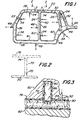
- Fig. 1 is a side view, partly broken away, of an automotive side frame structure, of the type which may be formed using the present invention.
- F ig. 2 is a view, taken along lines 2-2 of Fig. 1 illustrating generally a roof beam structure connected between two side frames of an automotive structure, and
- Fig. 3 is a cross sectional view taken along lines 3-3 of Fig. 1.
- FIG. 1 an automobile under frame structure 20 is illustrated, which is part of a door frame for an automobile.
- the sub or space frame structure 20 includes front post 22, center post 24 and rear post 26.
- the frame is designed to provide door openings 28 and 30 and a window opening 32.
- the sub frame structure 20 may include various joints, curved surfaces and areas of irregular cross-sections.
- a singular integral cured structure is formed from several prelocated, but unimpregnated, fiber pieces which are placed between upper and lower mold pieces and subsequently injected with resin. The impregnated fiber pieces are then suitably molded and cured.
- the structure 20 illustrated includes a hollow area extending therethrough.
- a source of resin is connected to a plurality of inlet ports 34 to impregnate the fiber or other reinforcement material 36 which ultimately forms the rigid sub frame structure 20.
- a plurality of channels or reservoirs 38, 40, 42, 44 and 46 which actually are in either the upper or lower mold piece.
- the grooves or reservoirs are disposed adjacent the fibrous material 36.
- the channels or reservoirs are disposed to receive the resin from the inlet ports 34, which are connected to a resin source, not illustrated.
- vent groove or channel 58 is disposed about the periphery of the frame, vent groove 60 is disposed at the center post 24, and vent groove 62 is disposed at the end post 26 to facilitate the venting of the air ports 45.
- the vent grooves or channels form parts of the upper of lower mold in the system.
- the present invention to be enphasized in Figs. 2 and 3 relates to providing a laterally extending integral beam from the structure 20, to eventually provide connecting means to an opposite side frame structure.
- a top view of an automotive structure formed includes a side underframe structure 20, as illustrated in F ig. 1, and an extending section or portion 70, integrally connected to the structure 20.
- the manner in which the section 70 is connected to the structure 20 will be described in connection with Fig. 3.
- the present invention contenplates a connection of a roof beam 72 connected from extending section 70 to a second extending section 74 connected to a second side frame structure 76.
- a top section 78 of the structure 20 ( F ig. 1), which may be part of the roof frame of an automotive structure, is disposed to be integrally attached to an "ear" or cross-member section 70 (Fig.2). This requires several preliminary steps to be taken.
- the pieces or sections of fabric 86, or other reinforcement material, must be prelocated within the upper mold piece 80 and lower mold 82. These pieces form an integral piece after the RZlr! operation.
- the upper and lower reinforcements inside the mold, as well as the crossmenber attachment "ears" must be preformed.
- the reinforcement used in the layup has a thermoplastic binder on it which allows the material to be shaped by heat and pressure.
- the precut shapes which form a complete charge are either individually or collectively thermoformed to form the configuration charge.
- fabric pieces 84 and 86 (each of which may conprise a plurality of pieces) is assembled inside the mold pieces 80 and 82.
- a bag 88 and any localized reinforcement is also inserted into the mold. If localized metal reinforcement is required, which should be primed, it should be properly located and could be hold in place by a layer of continuous strand mat over it.
- the mat may have thermoplastic binder which secures the metal reinforcement. Currently, however, additional glass is considered sufficient for most areas where metal inserts would be considered. Such metal reinforcements are not illustrated.
- the bag 88 may be a disposable polyethylene or other suitable material flat tubing which when inflated takes the shape of the mold. However, the bag is made from a blow molded material in some cases. The bag 88 is preinflated.
- the mold pieces 80 and 82 are first sprayed with release agent. This is a quick operation since the mold is heated and any solvent flashes off instantly.
- the crossmenber attachment "ear" 70 is then loaded in the mold, each as a preformed reinforcement charge with a core consisting of a pre-made "pillow” or bag 88 which is preinflated and extends partly into the cavity of the main frame 78 before a main bag 90 is inflated.
- the bag 90 is normally put into the mold in a deflated condition. This condition is illustrated by the dotted lines of the bags 88 and 90 in Fig. 3, with the solid lines representing the final positions of the bags prior to injection of the resin.
- the inflatible bag 90 which is inserted into the mold in the deflated condition and then inflated by a source of suitable gas through an inlet port 92.
- bag 90 inflates, it pushes against the inflated pillow or bag 88 causing it to extend into the ear or cross member 70 against the reinforcement 86 and takes the shepe of the interior of member 70.
- the bag 90 if it is a lay flat tubing, has to be sized by the largest internal perimeter of the section 78. It is then sealed at one end and looped around the frame. Two bags in one section of the frame should not cause a problem. The bag will then exit the mold at the trunk crossmember for quick attachment to an air inlet.
- the pillow 88 is partly inflated and sealed at both ends prior to iinsertion into the section 70.
Landscapes
- Engineering & Computer Science (AREA)
- Mechanical Engineering (AREA)
- Chemical & Material Sciences (AREA)
- Composite Materials (AREA)
- Casting Or Compression Moulding Of Plastics Or The Like (AREA)
- Moulding By Coating Moulds (AREA)
- Body Structure For Vehicles (AREA)
- Injection Moulding Of Plastics Or The Like (AREA)
- Moulds For Moulding Plastics Or The Like (AREA)
Abstract
Description
- The invention relates to a method of forming an integral reinforced structure having first and second sections extending in different directions.
- Known methods of forming hollow fiber reinforced structures include impregnating fiber material while utilizing an inflatable bladder. This present application utilizes many of the steps of these prior-art-methods, and involves an improvement in such methods.
- The prior-art-methods involve so-called resin transfer molding (RTM), wherein resin is applied to fiber material disposed between upper and lower mold pieces, with an inflatable bladder occupying a hollow area of the structures being formed.
- These methods are directed to forming structures in the same plane. However, in some cases, it is desirable to have portions of structures in one plane integrally connected to portions of structures extending in different planes. For example, in an automobile space or sub-frame, lateral roof beams between the side frames are sometimes required. Such lateral beams and other elements generally extend laterally from the side frames and at right angles thereto. It is desirable that these extending elements or sections be integral with the side frames.
- It is the object of this invention to provide an improved resin transfer molding system and method, in which the sections formed extend in different directions and are made integral with each other, and in which the formation of different extending sections of an integral automotive underframe may be formed.
- This object is obtained with the method of the generic kind omprising the steps of
- (a.) providing an outer mold with reinforcement material therein and including two mold pieces with one of said pieces having portions extending in different planes;
- (b.) placing an inflatable member in contact with said reinforcement material in the first of said sections;
- (c.) placing an inflated member in the second of said sections extending from said first section in contact with the reinforcement material within said first inflatable member;
- (d.) inflating said inflatable member against said inflated member to force said inflated member into said second section;
- (e.) injecting resin into said reinforcement material in both of said first and second sections, and
- (g.) curing said reinforcement material to form rigid reinforced structure.
- An additional preferred step includes providing a mold including two mold pieces with one of said pieces including a section extending in a different direction than the other piece.
- A further advantageous additional step includes placing said reinforcement material along the inner walls of said mold pieces. Here the inflatable member can be placed on said first section when said inflatable member is in a deflated condition.
- Preferably first channels are provided in one of said mold pieces to receive said resin.
- Conveniently second channels are provided in one of said mold pieces to vent air as resin is being injected into said reinforcement material.
- In accordance with the present invention, resin is applied to a fabric or other reinforcing material disposed between upper and lower mold pieces to form an integral structural member. The structural member may include a complete side frame of an automotive structure, for example, integrally connected to a laterally extending portion of a beam, which may be a roof beam for example, leading to an opposite side frame of the automotive structure sub or space frame. The invention is directed toward providing an integral structure formed by RIM in which sections extend in different directions. The mold including the upper and lower mold pieces will receive the reinforcement or fabric therein to be impregnated.
- Other objects and advantages of the present invention will be apparent from a reading of the following specification and claims, taken in conjunction with the accompanying drawings.
- Fig. 1 is a side view, partly broken away, of an automotive side frame structure, of the type which may be formed using the present invention.
- Fig. 2 is a view, taken along lines 2-2 of Fig. 1 illustrating generally a roof beam structure connected between two side frames of an automotive structure, and
- Fig. 3 is a cross sectional view taken along lines 3-3 of Fig. 1.
- Referring to Fig. 1 an automobile under
frame structure 20 is illustrated, which is part of a door frame for an automobile. The sub orspace frame structure 20 includesfront post 22,center post 24 andrear post 26. The frame is designed to providedoor openings - The
sub frame structure 20 may include various joints, curved surfaces and areas of irregular cross-sections. A singular integral cured structure is formed from several prelocated, but unimpregnated, fiber pieces which are placed between upper and lower mold pieces and subsequently injected with resin. The impregnated fiber pieces are then suitably molded and cured. Thestructure 20 illustrated includes a hollow area extending therethrough. - A source of resin is connected to a plurality of
inlet ports 34 to impregnate the fiber orother reinforcement material 36 which ultimately forms the rigidsub frame structure 20. Between theresin inlet ports 34 and thefibrous material 36, there are provided a plurality of channels orreservoirs fibrous material 36. The channels or reservoirs are disposed to receive the resin from theinlet ports 34, which are connected to a resin source, not illustrated. - When the resin is applied under pressures, the
fibrous material 36 is impregnated with the resin. A plurality ofair vents 48 is provided to vent the air as the resin is injected into thefibrous material 36. Vent groove orchannel 58 is disposed about the periphery of the frame, vent groove 60 is disposed at thecenter post 24, and vent groove 62 is disposed at theend post 26 to facilitate the venting of the air ports 45. The vent grooves or channels form parts of the upper of lower mold in the system. - The present invention to be enphasized in Figs. 2 and 3 relates to providing a laterally extending integral beam from the
structure 20, to eventually provide connecting means to an opposite side frame structure. - Referring to Fig. 2, a top view of an automotive structure formed, includes a
side underframe structure 20, as illustrated in Fig. 1, and an extending section orportion 70, integrally connected to thestructure 20. The manner in which thesection 70 is connected to thestructure 20 will be described in connection with Fig. 3. The present invention contenplates a connection of a roof beam 72 connected from extendingsection 70 to a second extendingsection 74 connected to a second side frame structure 76. - Referring to Fig. 3, a
top section 78 of the structure 20 (Fig. 1), which may be part of the roof frame of an automotive structure, is disposed to be integrally attached to an "ear" or cross-member section 70 (Fig.2). This requires several preliminary steps to be taken. - The pieces or sections of
fabric 86, or other reinforcement material, must be prelocated within theupper mold piece 80 andlower mold 82. These pieces form an integral piece after the RZlr! operation. The upper and lower reinforcements inside the mold, as well as the crossmenber attachment "ears" must be preformed. The reinforcement used in the layup has a thermoplastic binder on it which allows the material to be shaped by heat and pressure. The precut shapes which form a complete charge are either individually or collectively thermoformed to form the configuration charge. - In the present embodiment,
fabric pieces 84 and 86 (each of which may conprise a plurality of pieces) is assembled inside themold pieces - The bag 88 may be a disposable polyethylene or other suitable material flat tubing which when inflated takes the shape of the mold. However, the bag is made from a blow molded material in some cases. The bag 88 is preinflated.
- The
mold pieces main frame 78 before amain bag 90 is inflated. Thebag 90 is normally put into the mold in a deflated condition. This condition is illustrated by the dotted lines of thebags 88 and 90 in Fig. 3, with the solid lines representing the final positions of the bags prior to injection of the resin. Theinflatible bag 90, which is inserted into the mold in the deflated condition and then inflated by a source of suitable gas through aninlet port 92. Whenbag 90 inflates, it pushes against the inflated pillow or bag 88 causing it to extend into the ear orcross member 70 against thereinforcement 86 and takes the shepe of the interior ofmember 70. Thebag 90, if it is a lay flat tubing, has to be sized by the largest internal perimeter of thesection 78. It is then sealed at one end and looped around the frame. Two bags in one section of the frame should not cause a problem. The bag will then exit the mold at the trunk crossmember for quick attachment to an air inlet. The pillow 88 is partly inflated and sealed at both ends prior to iinsertion into thesection 70.
Claims (6)
Applications Claiming Priority (2)
| Application Number | Priority Date | Filing Date | Title |
|---|---|---|---|
| US06/854,235 US4724115A (en) | 1986-04-21 | 1986-04-21 | Method of forming composite structures having sections extending in different diections |
| US854235 | 1986-04-21 |
Publications (3)
| Publication Number | Publication Date |
|---|---|
| EP0243751A2 true EP0243751A2 (en) | 1987-11-04 |
| EP0243751A3 EP0243751A3 (en) | 1989-03-08 |
| EP0243751B1 EP0243751B1 (en) | 1990-08-08 |
Family
ID=25318113
Family Applications (1)
| Application Number | Title | Priority Date | Filing Date |
|---|---|---|---|
| EP87105237A Expired - Lifetime EP0243751B1 (en) | 1986-04-21 | 1987-04-08 | A method of forming an integral reinforced structure having sections extending in different directions |
Country Status (10)
| Country | Link |
|---|---|
| US (1) | US4724115A (en) |
| EP (1) | EP0243751B1 (en) |
| JP (1) | JPS6322618A (en) |
| KR (1) | KR940004801B1 (en) |
| CN (1) | CN1007883B (en) |
| AU (1) | AU590698B2 (en) |
| BR (1) | BR8701827A (en) |
| CA (1) | CA1273766A (en) |
| DE (1) | DE3764154D1 (en) |
| MX (1) | MX165722B (en) |
Cited By (7)
| Publication number | Priority date | Publication date | Assignee | Title |
|---|---|---|---|---|
| EP0322042A3 (en) * | 1987-12-21 | 1990-09-12 | Shell Internationale Research Maatschappij B.V. | Process reducing of mould cycle time |
| EP1459873A3 (en) * | 2003-03-20 | 2007-09-05 | The Boeing Company | Molding process and apparatus for producing unified composite structures |
| DE102011003626A1 (en) * | 2011-02-04 | 2012-08-09 | Bayerische Motoren Werke Aktiengesellschaft | Method for manufacturing side frame for e.g. cabriolet, involves pre-assembling shell element with hollow component, and solidifying shell element and hollow component to fiber composite component by transfer molding process |
| DE102011087497A1 (en) * | 2011-12-01 | 2013-06-06 | Bayerische Motoren Werke Aktiengesellschaft | Method for producing hollow fiber composite component for vehicles, involves carrying out solidification of prefabricated hollow fiber composite component with respect to a hollow fiber composite component, by a molding process |
| DE102014224040A1 (en) * | 2014-11-25 | 2016-05-25 | Bayerische Motoren Werke Aktiengesellschaft | Process for producing a structural component group and structural component group |
| WO2024127045A1 (en) * | 2022-12-16 | 2024-06-20 | Short Brothers Plc | Apparatus and methods for forming composite components |
| US20240227321A1 (en) * | 2023-01-10 | 2024-07-11 | Rohr, Inc. | Forming duct structure with overbraided woven fiber sleeve |
Families Citing this family (26)
| Publication number | Priority date | Publication date | Assignee | Title |
|---|---|---|---|---|
| US4863771A (en) * | 1985-08-22 | 1989-09-05 | The Budd Company | Hollow fiber reinforced structure and method of making same |
| US4902458A (en) * | 1987-05-12 | 1990-02-20 | Trimble Brent J | Method of molding composite bicycle frames |
| US4889355A (en) * | 1987-11-20 | 1989-12-26 | Trimble Brent J | Composite bicycle frames and methods of making same |
| US4986949A (en) * | 1986-05-12 | 1991-01-22 | Trimble Brent J | Method of making composite bicycle frames |
| JPH0628897B2 (en) * | 1986-06-30 | 1994-04-20 | 東燃化学株式会社 | Method for manufacturing automobile bumper |
| GB2195284B (en) * | 1986-09-17 | 1990-02-28 | Diversified Prod | Racquets |
| IL87589A0 (en) * | 1987-10-15 | 1989-01-31 | Lockheed Corp | Integrally stiffened composite structure |
| US4965030A (en) * | 1988-06-15 | 1990-10-23 | Therma-Tru Corp. | Method of forming a compression molded door assembly |
| US5016895A (en) * | 1989-07-19 | 1991-05-21 | Cycle Composites, Inc. | Cycle fork with fiber reinforced resin blades and crown and method of making same |
| US5078417A (en) * | 1989-07-19 | 1992-01-07 | Cycle Composites, Inc. | All terrain cycle fork with fiber reinforced resin blades and crown and method of making same |
| US5141273A (en) * | 1989-10-11 | 1992-08-25 | The Budd Company | Molded composite bumper |
| US5320373A (en) * | 1990-05-24 | 1994-06-14 | Medical Composite Technology | Molded-composite chassis for a wheelchair |
| US5233743A (en) * | 1990-05-24 | 1993-08-10 | Medical Composite Technology, Inc. | Method of construction for a composite wheelchair chassis |
| AU8054891A (en) * | 1990-05-24 | 1991-12-10 | Medical Composite Technology | Composite wheelchair chassis and method of making same |
| US5537789A (en) * | 1994-07-14 | 1996-07-23 | Therma-Tru Corp. | Compression molded door assembly |
| US5644870A (en) * | 1995-06-14 | 1997-07-08 | Nan Ya Plastics Corporation | Compression molded door assembly |
| US5762352A (en) * | 1996-03-15 | 1998-06-09 | Lee; Kyu-Wang | Bicycle fork having a fiber reinforced steerer tube and fiber reinforced crown and blades and method of making same |
| US5967592A (en) * | 1998-03-23 | 1999-10-19 | The Budd Company | Hollow FRP bumper |
| JP2003094449A (en) * | 2001-09-26 | 2003-04-03 | Toray Ind Inc | Method for manufacturing FRP structure |
| KR101151966B1 (en) * | 2004-02-17 | 2012-06-01 | 도레이 카부시키가이샤 | Rtm molding method and device |
| JP4928115B2 (en) * | 2005-11-08 | 2012-05-09 | 富士重工業株式会社 | Molding method and molding jig |
| US8480393B2 (en) * | 2008-06-13 | 2013-07-09 | Lockheed Martin Corporation | Vacuum-assisted resin transfer molding process with reusable resin distribution line |
| KR101484203B1 (en) | 2012-12-27 | 2015-01-16 | 현대자동차 주식회사 | Fiber reinforced plastic vehicle body structure and manufacturing method thereof |
| WO2019188586A1 (en) * | 2018-03-28 | 2019-10-03 | 株式会社エナテック | Application device and application method |
| WO2020148563A1 (en) * | 2019-01-18 | 2020-07-23 | 日産自動車株式会社 | Car body structure |
| CN113210220B (en) * | 2020-12-28 | 2022-07-08 | 飞旭电子(苏州)有限公司 | Three proofings are glued and are coated protection device |
Family Cites Families (11)
| Publication number | Priority date | Publication date | Assignee | Title |
|---|---|---|---|---|
| GB903734A (en) * | 1957-10-05 | 1962-08-15 | Alfred Kepka | Processes for the manufacture of hollow articles from reinforced synthetic resins |
| US3123017A (en) * | 1958-12-04 | 1964-03-03 | Open railroad car | |
| DE1102626B (en) * | 1959-10-21 | 1961-03-16 | Italtubi S P Az Soc Riunite G | Method and device for the production of hollow bodies from asbestos cement or the like formable material with outwardly projecting, massive wall parts |
| FR1354283A (en) * | 1963-01-25 | 1964-03-06 | Method of molding tubular parts, in particular masts and terminals, in synthetic resin | |
| FR2235785A1 (en) * | 1973-07-06 | 1975-01-31 | Desplat Marie | Light weight plastic moulded article has encapsulated hollow bodies - wrapped in fibrous matting |
| US4002707A (en) * | 1975-06-23 | 1977-01-11 | Michael Allen Oram | Method and apparatus for the construction of concrete shells |
| DE2706649A1 (en) * | 1977-02-23 | 1978-08-24 | Pilgrim Eng Dev | PIPE JOINT AND METHOD OF MANUFACTURING THE SAME |
| FR2460195A1 (en) * | 1979-07-02 | 1981-01-23 | Ferrary J P | METHOD FOR MANUFACTURING CYCLE RIM OR CYCLOMOTOR RIM |
| FR2490993A3 (en) * | 1980-10-01 | 1982-04-02 | Aerospatiale | Reusable mould for making complex hollow reinforced profiles - using an inflatable core in split rigid external mould |
| US4560523A (en) * | 1984-04-30 | 1985-12-24 | A&M Engineered Composites Corporation | Intrusion molding process for forming composite structures |
| DE3670788D1 (en) * | 1985-08-22 | 1990-06-07 | Budd Co | METHOD FOR PRODUCING A HOLLOW FIBER REINFORCED ITEM. |
-
1986
- 1986-04-21 US US06/854,235 patent/US4724115A/en not_active Expired - Fee Related
-
1987
- 1987-04-08 DE DE8787105237T patent/DE3764154D1/en not_active Expired - Lifetime
- 1987-04-08 EP EP87105237A patent/EP0243751B1/en not_active Expired - Lifetime
- 1987-04-09 CA CA000534235A patent/CA1273766A/en not_active Expired - Lifetime
- 1987-04-10 MX MX005993A patent/MX165722B/en unknown
- 1987-04-14 AU AU71499/87A patent/AU590698B2/en not_active Ceased
- 1987-04-15 BR BR8701827A patent/BR8701827A/en not_active IP Right Cessation
- 1987-04-20 KR KR1019870003764A patent/KR940004801B1/en not_active Expired - Lifetime
- 1987-04-20 JP JP62097246A patent/JPS6322618A/en active Granted
- 1987-04-20 CN CN87102925A patent/CN1007883B/en not_active Expired
Cited By (12)
| Publication number | Priority date | Publication date | Assignee | Title |
|---|---|---|---|---|
| EP0322042A3 (en) * | 1987-12-21 | 1990-09-12 | Shell Internationale Research Maatschappij B.V. | Process reducing of mould cycle time |
| EP1459873A3 (en) * | 2003-03-20 | 2007-09-05 | The Boeing Company | Molding process and apparatus for producing unified composite structures |
| DE102011003626A1 (en) * | 2011-02-04 | 2012-08-09 | Bayerische Motoren Werke Aktiengesellschaft | Method for manufacturing side frame for e.g. cabriolet, involves pre-assembling shell element with hollow component, and solidifying shell element and hollow component to fiber composite component by transfer molding process |
| DE102011003626B4 (en) * | 2011-02-04 | 2016-07-28 | Bayerische Motoren Werke Aktiengesellschaft | Method for producing a fiber composite component |
| DE102011087497A1 (en) * | 2011-12-01 | 2013-06-06 | Bayerische Motoren Werke Aktiengesellschaft | Method for producing hollow fiber composite component for vehicles, involves carrying out solidification of prefabricated hollow fiber composite component with respect to a hollow fiber composite component, by a molding process |
| DE102011087497B4 (en) * | 2011-12-01 | 2021-06-10 | Bayerische Motoren Werke Aktiengesellschaft | Process for the production of fiber composite hollow components and vehicles |
| DE102014224040A1 (en) * | 2014-11-25 | 2016-05-25 | Bayerische Motoren Werke Aktiengesellschaft | Process for producing a structural component group and structural component group |
| WO2016083071A1 (en) * | 2014-11-25 | 2016-06-02 | Bayerische Motoren Werke Aktiengesellschaft | Method for producing a structural subassembly and structural subassembly |
| US11806951B2 (en) | 2014-11-25 | 2023-11-07 | Bayerische Motoren Werke Aktiengesellschaft | Method for producing a structural subassembly and structural subassembly |
| WO2024127045A1 (en) * | 2022-12-16 | 2024-06-20 | Short Brothers Plc | Apparatus and methods for forming composite components |
| US20240227321A1 (en) * | 2023-01-10 | 2024-07-11 | Rohr, Inc. | Forming duct structure with overbraided woven fiber sleeve |
| US12397512B2 (en) * | 2023-01-10 | 2025-08-26 | Rohr, Inc. | Forming duct structure with overbraided woven fiber sleeve |
Also Published As
| Publication number | Publication date |
|---|---|
| DE3764154D1 (en) | 1990-09-13 |
| MX165722B (en) | 1992-12-02 |
| BR8701827A (en) | 1988-01-26 |
| JPS6322618A (en) | 1988-01-30 |
| JPH0435327B2 (en) | 1992-06-10 |
| AU7149987A (en) | 1987-10-22 |
| CN87102925A (en) | 1988-02-10 |
| KR940004801B1 (en) | 1994-06-01 |
| KR870009832A (en) | 1987-11-30 |
| EP0243751B1 (en) | 1990-08-08 |
| CN1007883B (en) | 1990-05-09 |
| AU590698B2 (en) | 1989-11-09 |
| CA1273766A (en) | 1990-09-11 |
| EP0243751A3 (en) | 1989-03-08 |
| US4724115A (en) | 1988-02-09 |
Similar Documents
| Publication | Publication Date | Title |
|---|---|---|
| EP0243751B1 (en) | A method of forming an integral reinforced structure having sections extending in different directions | |
| US4740346A (en) | Perimeter resin feeding of composite structures | |
| US4808362A (en) | Hollow reinforced fiber structure formed by resin transfer molding | |
| US4863771A (en) | Hollow fiber reinforced structure and method of making same | |
| CA2043747C (en) | Method of manufacturing fan blades | |
| CA1264908A (en) | Hollow fiber reinforced structure and method of making same | |
| US6767067B2 (en) | Structure for a vehicle seat element, and a method of making such a structure | |
| US5045251A (en) | Method of resin transfer molding a composite article | |
| US5213476A (en) | Fan blade | |
| US4911876A (en) | Method of forming an integral fiber reinforced structure | |
| US4635500A (en) | Epoxy steering wheel | |
| US4473520A (en) | Method for making an automotive steering wheel | |
| JPH04355105A (en) | Method of molding plastic hollow structural member | |
| EP0295819B1 (en) | Resin transfer molding core, preform and process | |
| KR0168132B1 (en) | Crash pad foam mold and its manufacturing method | |
| EP0295758B1 (en) | Method for forming a fiber reinforced structure | |
| JP3581990B2 (en) | Manufacturing method of ski surface members | |
| JP2003034297A (en) | Wing structure and manufacturing method thereof | |
| JP2522853Y2 (en) | Auxiliary tool for hollow fiber reinforced resin molding | |
| JPH04246510A (en) | Forming method of fiber reinforced resin formed body | |
| JPH08197647A (en) | Molding method for fiber reinforced plastic fan |
Legal Events
| Date | Code | Title | Description |
|---|---|---|---|
| PUAI | Public reference made under article 153(3) epc to a published international application that has entered the european phase |
Free format text: ORIGINAL CODE: 0009012 |
|
| AK | Designated contracting states |
Kind code of ref document: A2 Designated state(s): DE FR GB NL SE |
|
| PUAL | Search report despatched |
Free format text: ORIGINAL CODE: 0009013 |
|
| AK | Designated contracting states |
Kind code of ref document: A3 Designated state(s): DE FR GB NL SE |
|
| 17P | Request for examination filed |
Effective date: 19890626 |
|
| 17Q | First examination report despatched |
Effective date: 19891121 |
|
| GRAA | (expected) grant |
Free format text: ORIGINAL CODE: 0009210 |
|
| AK | Designated contracting states |
Kind code of ref document: B1 Designated state(s): DE FR GB NL SE |
|
| REF | Corresponds to: |
Ref document number: 3764154 Country of ref document: DE Date of ref document: 19900913 |
|
| ET | Fr: translation filed | ||
| PLBE | No opposition filed within time limit |
Free format text: ORIGINAL CODE: 0009261 |
|
| STAA | Information on the status of an ep patent application or granted ep patent |
Free format text: STATUS: NO OPPOSITION FILED WITHIN TIME LIMIT |
|
| 26N | No opposition filed | ||
| PGFP | Annual fee paid to national office [announced via postgrant information from national office to epo] |
Ref country code: SE Payment date: 19920319 Year of fee payment: 6 |
|
| PGFP | Annual fee paid to national office [announced via postgrant information from national office to epo] |
Ref country code: GB Payment date: 19920323 Year of fee payment: 6 |
|
| PGFP | Annual fee paid to national office [announced via postgrant information from national office to epo] |
Ref country code: FR Payment date: 19920410 Year of fee payment: 6 |
|
| PGFP | Annual fee paid to national office [announced via postgrant information from national office to epo] |
Ref country code: DE Payment date: 19920427 Year of fee payment: 6 |
|
| PGFP | Annual fee paid to national office [announced via postgrant information from national office to epo] |
Ref country code: NL Payment date: 19920430 Year of fee payment: 6 |
|
| PG25 | Lapsed in a contracting state [announced via postgrant information from national office to epo] |
Ref country code: GB Effective date: 19930408 |
|
| PG25 | Lapsed in a contracting state [announced via postgrant information from national office to epo] |
Ref country code: SE Effective date: 19930409 |
|
| PG25 | Lapsed in a contracting state [announced via postgrant information from national office to epo] |
Ref country code: NL Effective date: 19931101 |
|
| GBPC | Gb: european patent ceased through non-payment of renewal fee |
Effective date: 19930408 |
|
| NLV4 | Nl: lapsed or anulled due to non-payment of the annual fee | ||
| PG25 | Lapsed in a contracting state [announced via postgrant information from national office to epo] |
Ref country code: FR Effective date: 19931229 |
|
| PG25 | Lapsed in a contracting state [announced via postgrant information from national office to epo] |
Ref country code: DE Effective date: 19940101 |
|
| REG | Reference to a national code |
Ref country code: FR Ref legal event code: ST |
|
| EUG | Se: european patent has lapsed |
Ref document number: 87105237.9 Effective date: 19931110 |