EP0243625A2 - Geschwindigkeitsregelung für einen Gleichstrommotor - Google Patents
Geschwindigkeitsregelung für einen Gleichstrommotor Download PDFInfo
- Publication number
- EP0243625A2 EP0243625A2 EP87103372A EP87103372A EP0243625A2 EP 0243625 A2 EP0243625 A2 EP 0243625A2 EP 87103372 A EP87103372 A EP 87103372A EP 87103372 A EP87103372 A EP 87103372A EP 0243625 A2 EP0243625 A2 EP 0243625A2
- Authority
- EP
- European Patent Office
- Prior art keywords
- current
- during
- motor
- current value
- value
- Prior art date
- Legal status (The legal status is an assumption and is not a legal conclusion. Google has not performed a legal analysis and makes no representation as to the accuracy of the status listed.)
- Withdrawn
Links
Images
Classifications
-
- G—PHYSICS
- G11—INFORMATION STORAGE
- G11B—INFORMATION STORAGE BASED ON RELATIVE MOVEMENT BETWEEN RECORD CARRIER AND TRANSDUCER
- G11B19/00—Driving, starting, stopping record carriers not specifically of filamentary or web form, or of supports therefor; Control thereof; Control of operating function ; Driving both disc and head
- G11B19/20—Driving; Starting; Stopping; Control thereof
- G11B19/28—Speed controlling, regulating, or indicating
-
- H—ELECTRICITY
- H02—GENERATION; CONVERSION OR DISTRIBUTION OF ELECTRIC POWER
- H02P—CONTROL OR REGULATION OF ELECTRIC MOTORS, ELECTRIC GENERATORS OR DYNAMO-ELECTRIC CONVERTERS; CONTROLLING TRANSFORMERS, REACTORS OR CHOKE COILS
- H02P23/00—Arrangements or methods for the control of AC motors characterised by a control method other than vector control
- H02P23/0077—Characterised by the use of a particular software algorithm
-
- H—ELECTRICITY
- H02—GENERATION; CONVERSION OR DISTRIBUTION OF ELECTRIC POWER
- H02P—CONTROL OR REGULATION OF ELECTRIC MOTORS, ELECTRIC GENERATORS OR DYNAMO-ELECTRIC CONVERTERS; CONTROLLING TRANSFORMERS, REACTORS OR CHOKE COILS
- H02P6/00—Arrangements for controlling synchronous motors or other dynamo-electric motors using electronic commutation dependent on the rotor position; Electronic commutators therefor
- H02P6/06—Arrangements for speed regulation of a single motor wherein the motor speed is measured and compared with a given physical value so as to adjust the motor speed
Definitions
- This invention pertains to electric motor speed regulation and more particularly, to a technique for maintaining a desired motor speed using an uninterrupted motor winding current.
- Some devices such as data disk drive spindles, need continuous, precise speed regulation for correct operation. This must be accomplished without creating electrical noise that would interfere with the minute magnetic signals that are read from and written to the disk surface.
- the result can be accomplished by a drive that causes the motor winding current to vary between current levels rather than turning winding current on and off in response to the sensed need for power. To be most efficient there must be a minimum variation between the current levels. This requires frequent velocity sensing and current adjustment, typically several thousand times a second.
- a DC motor has a continuous flow of current in the windings which varies between a higher current value and a lower current value.
- the speed is sensed frequently with the higher current applied in response to a low speed and the lower current applied in response to an increased speed.
- the rotational speed of the motor is sensed about three thousand times per second.
- the motor current is varied between the selected upper and lower current levels to obtain a very closely regulated constant speed.
- a record is maintained of the number of time periods during which the respective upper and lower levels are utilized for a selected number of consecutive time periods. If the number of upper or lower time periods exceeds a threshold percentage, the current levels are revised. For example, if the higher current level is used during 70% or more of the time periods, the current levels are increased to more nearly approach the desired 50% duty cycle.
- the rotational speed is sensed during each revolution in an initial operating mode and during each sector time in a second operating mode to control the application of the higher and lower current levels.
- the revolution mode is used initially until the rotational speed is sufficiently regulated to permit the servo identification circuitry to synchronize with the rotating disk. Thereafter the speed is adjusted during each sector time or more than 50 times during each revolution to assure constant speed through corrections that occur more than 3000 times per second. It is during this final sector mode that the system is enabled to write data to and read data from the disk.
- the upper and lower current levels are each incremented or decremented to achieve an approximate 50% use of each current level.
- the upper and lower current levels are each raised or lowered to more nearly approach a 50% duty cycle with respect to the use of each current value.
- a four bit signal is utilized to identify sixteen current levels and the upper and lower values are separated by one value, so that for example an upper current value indicated by a hex value nine and a lower current value indicated by a hex value seven may be in use.
- the current values are changed to those indicated by a hex eight and a hex six.
- the current values are changed to those indicated by a hex eight and a hex "A".
- the invention is shown and described in the environment of a rigid magnetic disk drive (Fig.2) where high densities of data storage require precise control of numerous mechanical and electrical functions, including the rotational speed of the magnetic disks.
- the various functions of the device are controlled by a microprocessor, including the rotation of the disks 6 by spindle drive motor 14, movement of the actuator carriage 23 to position one of the transducer heads 25 over an addressed concentric data track and the reading and writing of data from or to the media surface.
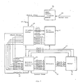
- the microprocessor controls the spindle drive motor of the disk drive using sixteen values of current. These values extend from approximately zero to five amps and in the device described range from a lowest or first value of 0,05 amps to a maximum or sixteenth value of 5,3 amps with increments of 0,35 amps. As seen in Fig. 1, the motor current is supplied from the predriver module in accordance with the respective hex values indicated on the lines data 4 through data 7. Data 4 is the most significant bit and data 7 the least significant bit. When all four bits are high the maximum current is supplied and when all four bit signals are low, the minimum current is delivered to the motor.
- the microprocessor 41 receives a signal from Hall 1 sensor on line 42 during each disk revolution.
- the sector information is derived from serial data received from the disks on serial data line 45. It is always synchronized.
- the servo ID module 44 must synchronize to this serial data so that sector information can be derived from the data.
- the data lines, data 4 through data 7, are half of an eight bit bus and carry the hex values established by microprocessor 41.
- the value of the bit combination on data 4 through data 7 are decoded by the spindle predrive module 48 to supply the selected one of the sixteen current values.
- Predrive module 48 activates selected drivers to supply the current value to the motor phase lines, Phase A through Phase C.
- the microprocessor transmits current values that rapidly accelerate the motor while limiting the current in the motor windings.
- current is continuously flowing in the motor at either a higher or a lower of two selected values in accordance with rotational velocity sensed.
- the servo ID module 44 after synchronizing with the data as the spindle speed approaches the regulated rotational velocity, decodes serial data received from the disk to determine the time for the passage of each sector and outputs a down level signal if the rotational speed is low and an up or positive signal if the speed of rotation equals or is greater than the established operating speed.
- Interface module 46 transmits the motor current hex value on lines data 4 through data 7 and provides a spindle latch signal on line 47 to indicate when the lines data 4 through data 7 carry valid motor current data.
- Spindle predriver module 48 decodes the value carried by lines data 4 through data 7 and coordinates the phase signals as a function of the signals on sensors Hall 1, Hall 2 and Hall 3.
- the driver circuits 50 activate the phase lines to supply current to the windings of the motor 51.
- the motor inhibit line is used to turn off the motor drivers, Phase A through Phase C whenever this line or the POR (power on reset) line is low and no motor driver will turn on regardless of other outputs.
- the spindle latch is used to latch the four data bits into the predrive module. With this line high, any change on the data lines will change the motor current. For the data to be reliably latched into the module, +spindle latch must be high for greater than a predetermined time, such as 100 nanoseconds with the data bits stable during this period. The data must also be held for a period such as 500 nanoseconds after +spindle latch goes low. After +spindle latch is low for 500 nanoseconds changes on the data 4 through data 7 lines will not affect the motor current.
- the lines +Hall 1, +Hall 2 and +Hall 3 are terminated in the predrive module and are used to commutate the motor and check for a hall error.
- +Hall 1 is also sent to the microprocessor to enable determination of the spindle speed.
- the +Hall error is generated by the spindle predrive module when an illegal combination of Hall signals occur. This is an all 1's or all 0's combination. +Hall error will only be high as long as the error occurs. If for example, one Hall sensor's output transistor was blown open with the motor turning at 332 radians/second, the error would be posted 3 times a revolution for one millisecond and there will be no motor current at these times.
- the three outputs of the motor drive transistors, Phase A, Phase B and Phase C supply the motor phase windings and can be sourcing or sinking current to/from the motor or floating.
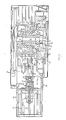
- Fig. 2 shows a vertical section of a magnetic disk drive which illustrates the principal components of a typical drive.
- the disks 6 (four of which are shown) are separated by spacers 7 and retained on hub 8 by a clamping assembly including a resilient bell member 9, a rigid ring 10 and a shrink ring 11.
- the disk assembly is mounted on the upper portion of spindle shaft 12 while the spindle drive motor rotor 13 is secured to the lower end of the spindle shaft.
- DC motor 14 provides a direct drive to rotate the data disks 6 as the disk assembly, spindle shaft 12 and rotor 13 turn in unison with the inner races of bearings 16 that mount the spindle shaft through the base casting assembly.
- the base casting assembly includes the base casting 18 and the bearing tower 19.
- the actuator assembly 20 is secured to base casting 18 with the carriage 23, suspension 24 and transducer heads 25 extending into the head-disk enclosure, defined by the base casting assembly and the cover 26, to permit the transducer portions of the heads 25 to access the disk data surfaces.
- the actuator carriage 23 is mounted for linear movement along cylindrical ways 27 secured to the actuator housing at each transverse side. Three pairs of rollers support carriage 23 on ways 27. Two pairs of rollers (not visible) engage the way 27 at the far side of the carriage.
- the roller pair 28 is longitudinally intermediate the other two pairs and engages the way (not shown) at the near side of carriage 23. One of the rollers 28 is spring biased against the cooperating way to remove any slack in the mechanical system.
- the carriage is driven by a voice coil wound on bobbin 29 and disposed in the working air gap 30.
- the carriage 23 reciprocates to move the read-write gaps of transducer heads 25 from track to track along a radius of the associated surface of the disks 6.
- the transducers that read and write data at the disk surface are electrically connected to the arm electronics module 32 on carriage 23 and from there to the electrical circuits (not shown) exterior of the disk enclosure by conductors that extend along the surface of the flat flexible member 33.
- the spindle drive motor 14 is positioned outside the disk enclosure and includes a permanent magnet rotor 13 attached to spindle shaft 12 and a surrounding stator, including a core 34 and windings 35 which are stationary, bolted to base casting 18. It is essential that the motor speed be closely regulated to assure that a constant condition exists with respect to the passage of concentric tracks on the disk surface past the transducing gap of the associated transducer head 25.
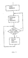
- Fig. 3 there are three stages or modes of control of the spindle motor drive.
- the spindle is accelerated rapidly to the operating rotational velocity.
- control is handed over to a rotation mode sequence that controls the spindle motor drive current until the sector ID module circuitry has been in sync with the serial data read from the disk surface for in excess of 40 consecutive revolutions.
- the servo ID module circuity With the servo ID module circuity in sync for more than 40 revolutions, control is placed in sector mode.
- sector mode the motor speed is sensed during each sector time and the higher or lower of two current values applied during the next subsequent sector time in accordance with the sensing of high or low motor speed. With approximately 70 sectors per track or revolution, speed is more closely regulated than in revolution mode where speed is sensed from Hall 1 and correction occurs once per revolution in accordance with speed sensed during the preceding revolution.
- the spindle drive motor is started under control of the microprocessor 41, using a start sequence, to afford high initial acceleration so that the transducer heads will fly quickly with minimal wear of either heads or disks while not using excessive power.
- the average power supply current delivered to the motor increases with speed if the current flowing in the motor is held at a constant value.
- the motor current is first set to the highest value of the sixteen values available using the four bit command on data lines 4 through 7 until the heads are safely flying above the disks. For the file described herein, this speed is approximately 80 radians per second. Since the average supply current has not risen too high at this speed and a safety factor is wanted, the motor current is not reduced until the disk speed is approximately 120 radians per second.
- the motor current is then reduced by one unit (about 0,35 amps.). As the motor current is reduced by one unit, the average supply current drops immediately and gradually ramps back up as the motor continues to pick up speed.
- the microprocessor uses Hall 1 to determine the velocity of the motor. At predetermined velocities the motor current is again reduced by one unit. This process of reducing the motor current as the motor accelerates continues until the desired velocity is reached.
- the microprocessor Upon attaining the desired velocity during three consecutive revolutions, the microprocessor provides two modes of speed control or speed regulation.
- the first is revolution control wherein speed is measured during each revolution, altered when necessary between two current values during a subsequent revolution and the current values changed adaptively after a predetermined number of revolutions in accordance with the duty cycle.
- This mode of controlling the current supplied once per revolution is continued until the servo ID module circuitry can be brought into sync with the servo data appearing once during each sector.
- the duty cycle is examined after 20 revolutions and the current values changed if the duty cycle using the present current values falls below 30% or exceeds 70%.
- the revolution mode uses the Hall 1 sensor signal occurring once per revolution which is communicated to the microprocessor 41 and the interface module 46 in addition to the spindle predrive module 48.
- the second mode of speed control is entered when the servo circuitry comes into sync with the servo data in each successive sector on a track and is used during drive operation to achieve the closest regulation during the reading and writing of data.
- speed is measured during the time of each sector passage (74 times per revolution in the environment described) and the current values are adaptively controlled after each revolution based on duty cycle.
- the servo identification module detects sectors and the time for the passage of a single sector. If the time for a sector passage is equal to or less than a predetermined value, a positive value is transmitted on the line and if the time exceeds the predetermined value a motor slow signal appears on line.
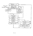
- Fig. 4 illustrates microprocessor speed control during revolution mode. Initially, the counter recording the number of revolutions (NUMREV) and the counter recording the number of revolutions during which the higher current level is applied (NUMHIGH) are set to zero. The system waits one revolution and determines the time duration for one revolution.
- NUMREV number of revolutions
- NUMHIGH number of revolutions during which the higher current level is applied
- the microprocessor If the time for one revolution indicates that the speed is equal to or exceeds the correct rotational speed, the microprocessor outputs bit values on lines data 4 through data 7 representing the lower or minimum of the two current values (MINCUR) and if a greater revolution time value is sensed, indicating a slower than desired rotational speed, the microprocessor outputs bit values on lines data 4 through data 7 representing the greater or maximum (MAXCUR) of the two current values being used and increments the counter (NUMHIGH) recording the number of revolutions during which the higher current value is being used. After each revolution, the NUMREV counter is incremented and the incremented count compared to the predetermined number of revolutions (REVCNT) associated with the adaptive control of the values of high current (MAXCUR) and low current (MINCUR) applied.
- REVCNT predetermined number of revolutions
- NUMREV is less than REVCNT
- the speed control is recycled to wait one revolution and again adjust the current as necessary.
- the adaptive control cycle is invoked to determine whether the MAXCUR and MINCUR values should be altered. In the example described the preferred duty cycle is 50%; however, between 30% and 70% duty cycle no adjustment is made. If the number of high current revolutions is greater than 70% or fewer than 30%, the current values (MAXCUR and MINCUR) are changed. In the example, using 20 revolutions, if the NUMHIGH is more than 14 or less than six the current values are changed. When NUMREV equals REVCNT, the NUMHIGH is compared to the minimum number of revolutions (MINREV).
- MINREV minimum number of revolutions
- both the MINCUR and MAXCUR are decremented one value within the sixteen selectable values. If the NUMHIGH is greater than the 70% duty cycle (14 of the 20 revolutions)and the MAXCUR is not at the highest current value (MAXVAL) of the sixteen selectable values, both MINCUR and MAXCUR are incremented one value within the sixteen selectable values. If the duty cycle is between 30% and 70%, the MINVAL is in use with a duty cycle exceeding 70% or the MAXVAL is in use with a duty cycle of less than 30%, no current value adjustment is made. Thereafter the NUMREV and NUMHIGH counters are reset to zero and the cycle of operation repeated.
- the revolution mode of operation shown in Fig. 4 continues until the speed is regulated to a sufficiently constant value to permit the circuitry of servo identification module 44 (SID) to come into sync with data received from the rotating disk.
- SID servo identification module 44
- the speed control shifts from the initial revolution mode to sector mode.
- the operation in sector mode is identical to revolution mode; however, much closer speed regulation can be maintained since, with 74 sectors on a track, the current correction occurs 74 times per revolution and the current upper and lower values are adjusted as necessary each revolution rather than after 20 revolutions.
- Sector mode operates in a manner identical to revolution mode, but counts 74 sectors during a revolution rather than 20 consecutive revolutions. During sector mode where the disk has 74 sectors per track, the number of sectors are counted until the count (REVCNT) equals 74 and the wait period is of one sector duration rather than one revolution. If the number of sectors during which high current is applied (NUMHIGH) is less than 30 percent (22 or fewer sectors) and the system is not operating at the minimum current (MINVAL) the current values are each decremented. If the number of sectors during which high current is applied (NUMHIGH) is greater than 70 percent (52 or more sectors), and the maximum current (MAXCUR) is not being used as the high current value, both current values are incremented.
- the speed regulation is effected by varying between the high and low current values 74 times per revolution rather than once each revolution and the current values are adaptively controlled after one revolution rather than after 20 revolutions.
- the rotational velocity of the disks is very closely regulated.
Landscapes
- Engineering & Computer Science (AREA)
- Power Engineering (AREA)
- Control Of Direct Current Motors (AREA)
- Control Of Motors That Do Not Use Commutators (AREA)
Applications Claiming Priority (2)
| Application Number | Priority Date | Filing Date | Title |
|---|---|---|---|
| US85687386A | 1986-04-28 | 1986-04-28 | |
| US856873 | 1986-04-28 |
Publications (2)
| Publication Number | Publication Date |
|---|---|
| EP0243625A2 true EP0243625A2 (de) | 1987-11-04 |
| EP0243625A3 EP0243625A3 (de) | 1989-08-16 |
Family
ID=25324682
Family Applications (1)
| Application Number | Title | Priority Date | Filing Date |
|---|---|---|---|
| EP87103372A Withdrawn EP0243625A3 (de) | 1986-04-28 | 1987-03-10 | Geschwindigkeitsregelung für einen Gleichstrommotor |
Country Status (2)
| Country | Link |
|---|---|
| EP (1) | EP0243625A3 (de) |
| JP (1) | JPS62260575A (de) |
Cited By (1)
| Publication number | Priority date | Publication date | Assignee | Title |
|---|---|---|---|---|
| EP0880222A1 (de) * | 1997-05-23 | 1998-11-25 | Deutsche Thomson-Brandt Gmbh | Schaltung und Verfahren für den Betrieb eines Elektromotors |
Family Cites Families (3)
| Publication number | Priority date | Publication date | Assignee | Title |
|---|---|---|---|---|
| US4197489A (en) * | 1978-01-27 | 1980-04-08 | Mfe Corporation | Spindle drive system |
| US4250435A (en) * | 1980-01-04 | 1981-02-10 | General Electric Company | Clock rate control of electronically commutated motor rotational velocity |
| US4555651A (en) * | 1983-01-05 | 1985-11-26 | Towmotor Corporation | Motor speed control apparatus |
-
1987
- 1987-03-10 EP EP87103372A patent/EP0243625A3/de not_active Withdrawn
- 1987-03-26 JP JP62070562A patent/JPS62260575A/ja active Pending
Cited By (2)
| Publication number | Priority date | Publication date | Assignee | Title |
|---|---|---|---|---|
| EP0880222A1 (de) * | 1997-05-23 | 1998-11-25 | Deutsche Thomson-Brandt Gmbh | Schaltung und Verfahren für den Betrieb eines Elektromotors |
| US6337553B1 (en) | 1997-05-23 | 2002-01-08 | Deutsche Thomson-Brandt Gmbh | Circuit arrangement and method for operating and electrical motor |
Also Published As
| Publication number | Publication date |
|---|---|
| JPS62260575A (ja) | 1987-11-12 |
| EP0243625A3 (de) | 1989-08-16 |
Similar Documents
| Publication | Publication Date | Title |
|---|---|---|
| US5012166A (en) | Control system for brushless DC motor | |
| US5872669A (en) | Disk drive apparatus with power conservation capability | |
| EP0456371B1 (de) | Steuerungsmethode der Zugriffsbewegungen mittels eines Magnetkopfes in einem harten Plattenantrieb | |
| US5231549A (en) | Disk drive apparatus with cam and follower for unloading heads | |
| US6359746B1 (en) | Magnetic disk drive | |
| US5936787A (en) | Method and apparatus for reducing vibration on a disk spindle motor by detecting the vibrations and correcting the motor driving signal according to the detected vibration | |
| US5291110A (en) | Low acoustic noise seeking method and apparatus | |
| US4630145A (en) | Fine positioning apparatus for floppy disk drive | |
| EP0769774A2 (de) | Zurückziehen eines Plattenantriebsarmes | |
| JPH09167305A (ja) | ランディング・ゾーンにおけるヘッドとディスクの磨耗を最小限に抑えたディスク・ドライブ | |
| US6282049B1 (en) | Applying a ramped voltage source across an actuator coil to retract a disc drive actuator | |
| JP2002520758A (ja) | 目標トラック位置への適応的速度曲線探索 | |
| US6388413B1 (en) | Head switch seek on disc drives with multiple recording heads | |
| USRE37825E1 (en) | Data storage device having a drive mechanism for rotating a data storage medium | |
| US5329409A (en) | Correction of current feedback offset for disc drive servo systems | |
| US5001578A (en) | Method and system for controlling disk recording and reproduction apparatus for reduced power consumption | |
| EP0799478B1 (de) | System und verfahren zur kontrolle der suchoperation in einer platte | |
| EP0243625A2 (de) | Geschwindigkeitsregelung für einen Gleichstrommotor | |
| US5530602A (en) | Disk drive micromotion starting apparatus and method | |
| JPH08212689A (ja) | データ記憶システムのスピンドル・モータのパフォーマンス低下検出方法およびシステム | |
| EP0537916A2 (de) | Armbetätigungs-Steuerschaltung für Plattenantriebssystem | |
| US4477750A (en) | Multi-level disk drive motor speed control | |
| US5283702A (en) | Power saving system for rotating disk data storage apparatus | |
| US4872074A (en) | Data transducer position control system for rotating disk data storage equipment | |
| JPH01116972A (ja) | 記憶装置 |
Legal Events
| Date | Code | Title | Description |
|---|---|---|---|
| PUAI | Public reference made under article 153(3) epc to a published international application that has entered the european phase |
Free format text: ORIGINAL CODE: 0009012 |
|
| AK | Designated contracting states |
Kind code of ref document: A2 Designated state(s): DE FR GB |
|
| 17P | Request for examination filed |
Effective date: 19880224 |
|
| PUAL | Search report despatched |
Free format text: ORIGINAL CODE: 0009013 |
|
| AK | Designated contracting states |
Kind code of ref document: A3 Designated state(s): DE FR GB |
|
| 17Q | First examination report despatched |
Effective date: 19910514 |
|
| STAA | Information on the status of an ep patent application or granted ep patent |
Free format text: STATUS: THE APPLICATION IS DEEMED TO BE WITHDRAWN |
|
| 18D | Application deemed to be withdrawn |
Effective date: 19911126 |
|
| RIN1 | Information on inventor provided before grant (corrected) |
Inventor name: RESMAN, JOHN BORIS Inventor name: KORECKY, JAMES JOSEPH |