EP0243587A2 - Refractory body, particularly a plate for a sliding gate valve - Google Patents
Refractory body, particularly a plate for a sliding gate valve Download PDFInfo
- Publication number
- EP0243587A2 EP0243587A2 EP87101325A EP87101325A EP0243587A2 EP 0243587 A2 EP0243587 A2 EP 0243587A2 EP 87101325 A EP87101325 A EP 87101325A EP 87101325 A EP87101325 A EP 87101325A EP 0243587 A2 EP0243587 A2 EP 0243587A2
- Authority
- EP
- European Patent Office
- Prior art keywords
- plate
- base body
- insert
- expansion joints
- refractory
- Prior art date
- Legal status (The legal status is an assumption and is not a legal conclusion. Google has not performed a legal analysis and makes no representation as to the accuracy of the status listed.)
- Granted
Links
- CPLXHLVBOLITMK-UHFFFAOYSA-N Magnesium oxide Chemical compound [Mg]=O CPLXHLVBOLITMK-UHFFFAOYSA-N 0.000 claims abstract description 25
- 239000000395 magnesium oxide Substances 0.000 claims abstract description 12
- 229910052574 oxide ceramic Inorganic materials 0.000 claims abstract description 5
- 239000008187 granular material Substances 0.000 claims abstract description 4
- 239000004570 mortar (masonry) Substances 0.000 claims abstract description 4
- XEEYBQQBJWHFJM-UHFFFAOYSA-N iron Substances [Fe] XEEYBQQBJWHFJM-UHFFFAOYSA-N 0.000 claims abstract description 3
- 229910052742 iron Inorganic materials 0.000 claims abstract description 3
- 239000000463 material Substances 0.000 claims description 10
- 238000010438 heat treatment Methods 0.000 claims description 6
- 239000011224 oxide ceramic Substances 0.000 claims description 4
- 239000012768 molten material Substances 0.000 abstract 2
- 238000000465 moulding Methods 0.000 abstract 2
- 239000002131 composite material Substances 0.000 abstract 1
- 238000005266 casting Methods 0.000 description 3
- RVTZCBVAJQQJTK-UHFFFAOYSA-N oxygen(2-);zirconium(4+) Chemical compound [O-2].[O-2].[Zr+4] RVTZCBVAJQQJTK-UHFFFAOYSA-N 0.000 description 3
- 229910001928 zirconium oxide Inorganic materials 0.000 description 3
- 230000015572 biosynthetic process Effects 0.000 description 2
- 230000000149 penetrating effect Effects 0.000 description 2
- 230000035882 stress Effects 0.000 description 2
- 229910019142 PO4 Inorganic materials 0.000 description 1
- PNEYBMLMFCGWSK-UHFFFAOYSA-N aluminium oxide Inorganic materials [O-2].[O-2].[O-2].[Al+3].[Al+3] PNEYBMLMFCGWSK-UHFFFAOYSA-N 0.000 description 1
- 239000004568 cement Substances 0.000 description 1
- 239000000919 ceramic Substances 0.000 description 1
- 239000004927 clay Substances 0.000 description 1
- 230000007797 corrosion Effects 0.000 description 1
- 238000005260 corrosion Methods 0.000 description 1
- 230000006378 damage Effects 0.000 description 1
- 230000001066 destructive effect Effects 0.000 description 1
- 238000005516 engineering process Methods 0.000 description 1
- 230000008014 freezing Effects 0.000 description 1
- 238000007710 freezing Methods 0.000 description 1
- 238000009499 grossing Methods 0.000 description 1
- 230000003993 interaction Effects 0.000 description 1
- 238000004519 manufacturing process Methods 0.000 description 1
- 229910052751 metal Inorganic materials 0.000 description 1
- 239000002184 metal Substances 0.000 description 1
- 238000000034 method Methods 0.000 description 1
- 239000000203 mixture Substances 0.000 description 1
- 230000035515 penetration Effects 0.000 description 1
- 230000002093 peripheral effect Effects 0.000 description 1
- NBIIXXVUZAFLBC-UHFFFAOYSA-K phosphate Chemical compound [O-]P([O-])([O-])=O NBIIXXVUZAFLBC-UHFFFAOYSA-K 0.000 description 1
- 239000010452 phosphate Substances 0.000 description 1
- 239000002694 phosphate binding agent Substances 0.000 description 1
- 239000011819 refractory material Substances 0.000 description 1
- 238000007493 shaping process Methods 0.000 description 1
- 238000005496 tempering Methods 0.000 description 1
- 230000008646 thermal stress Effects 0.000 description 1
Images
Classifications
-
- C—CHEMISTRY; METALLURGY
- C04—CEMENTS; CONCRETE; ARTIFICIAL STONE; CERAMICS; REFRACTORIES
- C04B—LIME, MAGNESIA; SLAG; CEMENTS; COMPOSITIONS THEREOF, e.g. MORTARS, CONCRETE OR LIKE BUILDING MATERIALS; ARTIFICIAL STONE; CERAMICS; REFRACTORIES; TREATMENT OF NATURAL STONE
- C04B35/00—Shaped ceramic products characterised by their composition; Ceramics compositions; Processing powders of inorganic compounds preparatory to the manufacturing of ceramic products
- C04B35/66—Monolithic refractories or refractory mortars, including those whether or not containing clay
-
- B—PERFORMING OPERATIONS; TRANSPORTING
- B22—CASTING; POWDER METALLURGY
- B22D—CASTING OF METALS; CASTING OF OTHER SUBSTANCES BY THE SAME PROCESSES OR DEVICES
- B22D41/00—Casting melt-holding vessels, e.g. ladles, tundishes, cups or the like
- B22D41/14—Closures
- B22D41/22—Closures sliding-gate type, i.e. having a fixed plate and a movable plate in sliding contact with each other for selective registry of their openings
- B22D41/28—Plates therefor
Definitions
- the invention relates to a refractory molded body having at least one flow opening for molten metal, in particular a plate or sleeve for slide closures on the pouring of metallurgical vessels, with a base body made of cold-setting refractory concrete and at least one high-quality oxide ceramic insert molded therein.
- DE-AS 27 19 105 plates are known, in which the base body including the ceramic insert consists of refractory concrete.
- the oxide ceramic insert has certain property values and is made of MgO, Cr 2 0 3 , A1 2 0 3 or Zr0 2 or mixtures of these oxides, while the refractory concrete of the base body consists of 70 to 95% by weight of tabular clay and 5 to 30 % By weight of alumina cement with 80 to 96% by weight of A1 2 0 3 .
- the present invention is a further development, in particular of plates and sleeves used on slide closures, which are composed according to the principle of DE-AS 27 19 105 and pursues the task of further improving the durability, in particular of plates, by using a corrosion-resistant, because of its Brittleness of previously unused refractory concrete for the production of the basic body.
- the base body surrounding the high-value inserts consists of chemically setting refractory concrete with low-iron sintered magnesia of over 80% by weight Mg0 as refractory granules and, after the setting, runs in the direction of the flow opening after the heat treatment the molded body has mortared expansion joints.
- the base body surrounding the high-value inserts consists of chemically setting refractory concrete with low-iron sintered magnesia of over 80% by weight Mg0 as refractory granules and, after the setting, runs in the direction of the flow opening after the heat treatment the molded body has mortared expansion joints.
- a base body made of sintered magnesia is also extremely resistant to any destructive frictional forces that may occur between the plates due to freezing.
- the use of refractory concrete with sintered magnesia as refractory granules can be used risk-free due to the arrangement of expansion joints, because the joints meet the relatively low resistance to temperature changes of the magnesia and prevent stress cracks that occur during the heat treatment of the slab after it has set or dried Basic body would otherwise occur. It is only the interaction of the material variant with the expansion joint technology that makes the panel ready for use, which is extremely economical due to the uniform wear of the base body and the oxide-ceramic insert panel and the resulting higher casting quantities.
- the invention proposes that in the formation of a plate in the base body at least two transverse to the P long sides and half of the length of the plate opposite expansion joints are provided, the expansion joints penetrating at least over the thickness of the plate insert reaching into the base body. It is different with inlet or outlet sleeves in which at least one expansion joint is arranged radially in the base body. Incidentally, all closed expansion joints expediently have a mortar filling made of the material of the base body.
- the slide plate 1 has a base body made of kaltabbindendem, for example, casting or ruttelnetem refractory material 2 having formed therein parts of high wear-resistant material in the form of an insert plate 3 on the sliding surface 4 and an E insatzringes 5, the flow-through opening 6 of the Surrounds slide plate 1 below the insert plate 3.
- the insert plate 3 and the insert ring 5 are prefabricated from a highly refractory oxide, for example zirconium oxide, and are accommodated in an adjusted manner in a casting mold and finally surrounded by the formable material made of sintered magnesia of the base body 2 that chemically sets by adding phosphate.
- the slide plate 1 which has been removed from the mold has molded-in expansion joints 7, which are arranged at about half the length of the plate, transversely to the longitudinal axis of the plate in the base body, extending from the sliding surface 4 across the thickness of the insert plate 3.
- the joints are designed using mold cores (FIG. 3) which have a wedge shape to enable easy removal from the set base body material, for example from the sliding surface, and serve to cause thermal stresses in the base body 2 during the heat treatment of the slide plate 1 that lead to cracks avoid.
- the joints 6, of which more than two can be arranged distributed over the circumference of the plate are closed by filling in and smoothing out basic body material, a work which is facilitated by the wedge-shaped design of the expansion joints .
- the procedure is similar for the sleeve 11 according to FIGS. 4 and 5, which also has a base body 12 made of sintered magnesia, into which an insert sleeve 13 made of zirconium oxide forming the flow opening 16 is molded.
- the expansion joint 14 to be closed after the heat treatment has ended extends in the longitudinal direction in the sleeve 11 and runs continuously radially from the outer to the inner circumference of the base body 12.
- the joint 14 can be formed by a mold core 18 which is radially removable from the base body 12 and is wedge-shaped in this direction be educated. Depending on requirements, several such expansion joints 14 can also be provided with non-continuous or smaller radial penetration depths in the base body.
- FIG. 6 shows the shaping of a base plate 21.
- the insert plate 23 prefabricated from zirconium oxide is first placed with the sliding surface 24 on a smooth base 20 and an insert ring 25 is built thereon by means of an adjusting part 29 provided in the flow opening 26. Adjusted over it is then turned a mold 30 which has shaped wedges 28 on the inside on the longitudinal sides and filling openings 31 and 32 through which the material forming the base body 22, consisting of a sintered magnesia containing phosphate binder, is filled. After the filled material has set, the mold is lifted off and the base plate 21, which in this case has continuous expansion joints 27 over the entire plate thickness, is annealed at 250 to 300 ° C. for about 12 hours. Then the joints 27 are grouted with the filled sintered magnesia.
- the thickness of the joints 7, 14, 27, their formation and arrangement on a molded body 1, 11, 21 largely depends on its shape and size. For large-format panels, for example for oven slide closures, a joint thickness between 3 and 4 mm has proven to be useful.
Landscapes
- Engineering & Computer Science (AREA)
- Chemical & Material Sciences (AREA)
- Ceramic Engineering (AREA)
- Mechanical Engineering (AREA)
- Structural Engineering (AREA)
- Materials Engineering (AREA)
- Manufacturing & Machinery (AREA)
- Organic Chemistry (AREA)
- Casting Support Devices, Ladles, And Melt Control Thereby (AREA)
- Compositions Of Oxide Ceramics (AREA)
- Sealing Material Composition (AREA)
- Furnace Charging Or Discharging (AREA)
- Manufacture Of Macromolecular Shaped Articles (AREA)
- Sliding Valves (AREA)
Abstract
Description
Die Erfindung betrifft einen feuerfesten, wenigstens eine Durchflußöffnung für metallische Schmelze aufweisenden Formkörper, insbesondere Platte oder Hülse für Schieberverschlüsse am Ausguß metallurgischer Gefäße, mit einem Grundkörper aus kaltabbindendem Feuerbeton und wenigstens einem darin eingeformten oxidkeramischen Hochwerteinsatz.The invention relates to a refractory molded body having at least one flow opening for molten metal, in particular a plate or sleeve for slide closures on the pouring of metallurgical vessels, with a base body made of cold-setting refractory concrete and at least one high-quality oxide ceramic insert molded therein.
Diesbezüglich sind aus der DE-AS 27 19 105 Platten bekannt, bei denen der den keramischen Einsatz einschließende Grundkörper aus Feuerbeton besteht. Hierbei weist der oxidkeramische Einsatz bestimmte Eigenschaftswerte auf und ist aus MgO, Cr203, A1203 oder Zr02 oder aus Mischungen dieser Oxide gefertigt, indessen der Feuerbeton des Grundkörpers aus 70 bis 95 Gew.-% Tabulartonerde und 5 bis 30 Gew.-% Tonerdezement mit 80 bis 96 Gew.-% A1203 besteht.In this regard, DE-AS 27 19 105 plates are known, in which the base body including the ceramic insert consists of refractory concrete. The oxide ceramic insert has certain property values and is made of MgO, Cr 2 0 3 , A1 2 0 3 or Zr0 2 or mixtures of these oxides, while the refractory concrete of the base body consists of 70 to 95% by weight of tabular clay and 5 to 30 % By weight of alumina cement with 80 to 96% by weight of A1 2 0 3 .
Vorliegende Erfindung ist eine Weiterentwicklung insbesondere von an Schieberverschlüssen verwendeten Platten und Hülsen, die sich nach dem Prinzip der DE-AS 27 19 105 zusammensetzen und verfolgt die Aufgabe, die Haltbarkeit insbesondere von Platten noch weiter zu verbessern, durch die Verwendung eines korrosionsbeständigen, wegen seiner Sprödigkeit bisher nicht einsetzbaren Feuerbetons zur Herstellung des Grundkörpers.The present invention is a further development, in particular of plates and sleeves used on slide closures, which are composed according to the principle of DE-AS 27 19 105 and pursues the task of further improving the durability, in particular of plates, by using a corrosion-resistant, because of its Brittleness of previously unused refractory concrete for the production of the basic body.
Die gestellte Aufgabe wird gemäß der Erfindung im wesentlich dadurch gelöst, daß der die Hochwerteinsätze umgebende Grundkörper aus chemisch abbindendem Feuerbeton mit eisenarmer Sintermagnesia von über 80 Gew.-% Mg0 als feuerfestes Granulat besteht und nach der Abbindung in Richtung der Durchflußöffnung verlaufende, nach der Wärmebehandlung des Formkörpers vermörtelte Dehnfugen aufweist. Auf diese Weise gelingt es, insbesondere in Schieberverschlüssen eingesetzten Platten eine vergleichsweise längere Haltbarkeit zu geben, weil beispielsweise während des Schieberbetriebes zwischen die Platten eindringende und über den Umfangsrand des Hochwerteinsatzes auf die Grundkörperfläche gelangende Schmelze, dort weniger korrosive Zerstörungen anrichten kann als bisher. Auch gegenUber etwaigen zwischen den Platten durch Einfrierungen auftretenden, zerstörenden Reibungskräften ist ein Grundkörper aus Sintermagnesia äußerst widerstandsfähig. Hinzu kommt, daß die Verwendung von Feuerbeton mit Sintermagnesia als feuerfestes Granulat durch die Anordnung von Dehnfugen risikofrei eingesetzt werden kann, denn die Fugen kommen der relativ geringen Temperaturwechselbeständigkeit der Magnesia entgegen und beugen Spannungsrissen vor, die während der Wärmebehandlung der Platte nach abgebundenem bzw. getrocknetem Grundkörper ansonsten auftreten würden. Erst das Zusammenwirken der Materialvariante mit der Dehnfugentechnik macht die Platte einsatzfähig, die infolge eines gleichmäßigen Verschleißes von Grundkörper und oxidkeramischer Einsatzplatte sowie dadurch möglicher höherer Abgußmengen eine hervorragende Wirtschaftlichkeit besitzt.The stated object is achieved according to the invention essentially in that the base body surrounding the high-value inserts consists of chemically setting refractory concrete with low-iron sintered magnesia of over 80% by weight Mg0 as refractory granules and, after the setting, runs in the direction of the flow opening after the heat treatment the molded body has mortared expansion joints. In this way, it is possible to provide a comparatively longer shelf life, in particular for plates used in slide closures, because, for example, during the slide operation, melt penetrating between the plates and reaching the base body surface via the peripheral edge of the high-value insert can cause less corrosive destruction there than previously. A base body made of sintered magnesia is also extremely resistant to any destructive frictional forces that may occur between the plates due to freezing. In addition, the use of refractory concrete with sintered magnesia as refractory granules can be used risk-free due to the arrangement of expansion joints, because the joints meet the relatively low resistance to temperature changes of the magnesia and prevent stress cracks that occur during the heat treatment of the slab after it has set or dried Basic body would otherwise occur. It is only the interaction of the material variant with the expansion joint technology that makes the panel ready for use, which is extremely economical due to the uniform wear of the base body and the oxide-ceramic insert panel and the resulting higher casting quantities.
Für gleichermaßen ausgebildete Einlauf- bzw. Auslaufhülsen für Schieberverschlüsse gelten die vorstehend aufgezeigten betrieblichen Beanspruchungen zwar nicht, doch sind die Hülsen mit Bezug auf Haltbarkeit und im Rahmen des Konzepts, gleiche Materialien im Schieberverschluß einzusetzen, den Platten durchaus ebenbürtig.The operating stresses outlined above do not apply to equally designed inlet and outlet sleeves for slide closures, but the sleeves are on a par with the plates in terms of durability and within the scope of the concept of using the same materials in the slide closure.
Hinsichtlich der näheren Gestaltung der Dehnfugen ist es vorteilhaft, diese mit dem breiten Ende zur Körperoberfläche hin keilförmig auszubilden. Dadurch wird das Entfernen der die Dehnfugen formenden Formkerne nach dem Abbinden des Grundkörpers und ein Ausmörteln der Fugen nach dem Tempern der Platte erleichtert. Im weiteren schlägt die Erfindung vor, daß bei der Ausbildung einer Platte im Grundkörper wenigstens zwei zu den Plattenlängsseiten quere und im hälftigen Bereich der Plattenlänge sich gegenüberstehende Dehnfugen vorgesehen sind, wobei die Dehnfugen wenigstens über die Dicke des Platteneinsatzes reichend in den Grundkörper eindringen. Anders bei Ein- oder Auslaufhülsen, bei denen wenigstens eine Dehnfuge radial im Grundkörper angeordnet ist. Obrigens weisen zweckmäßig alle geschlossenen Dehnfugen eine Mörtel füllung aus dem Material des Grundkörpers auf.With regard to the closer design of the expansion joints, it is advantageous to make them wedge-shaped with the broad end towards the body surface. This makes it easier to remove the mold cores that form the expansion joints after the base body has set and to mortar the joints after the plate has been tempered. Furthermore, the invention proposes that in the formation of a plate in the base body at least two transverse to the P long sides and half of the length of the plate opposite expansion joints are provided, the expansion joints penetrating at least over the thickness of the plate insert reaching into the base body. It is different with inlet or outlet sleeves in which at least one expansion joint is arranged radially in the base body. Incidentally, all closed expansion joints expediently have a mortar filling made of the material of the base body.
Die Erfindung ist nachstehend anhand der Zeichnung erläutert.
Figur 1 zeigt eine Schieberplatte in Sicht auf die Gleitfläche,Figur 2 einen Schnitt nach der Linie A-A derFigur 1,Figur 3 eine Einzelheit zuFiguren 1 und 2,- Figur 4 eine zur Schieberplatte nach
Figuren 1 und 2 passende Auslaufhülse in teil geschnittenem Aufriß, Figur 5 eine Draufsicht in Richtung Pfeil B nachFigur 3, undFigur 6 eine längsmittig geschnittene Bodenplatte mit strichpunktiert angedeuteter Gießform.
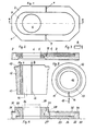
- FIG. 1 shows a slide plate in view of the sliding surface,
- FIG. 2 shows a section along the line AA in FIG. 1,
- 3 shows a detail of FIGS. 1 and 2,
- FIG. 4 shows an outlet sleeve matching the slide plate according to FIGS. 1 and 2 in a partially sectioned elevation,
- Figure 5 is a plan view in the direction of arrow B of Figure 3, and
- Figure 6 is a longitudinally cut bottom plate with a dash-dotted mold.
Die Schieberplatte 1 nach Figuren 1 und 2 hat einen aus kaltabbindendem, beispielsweise gieß- oder ruttelfähigem feuerfesten Material hergestellten Grundkörper 2 mit darin eingeformten Teilen aus hochverschleißfestem Material in Form einer Einsatzplatte 3 an der Gleitfläche 4 und eines Einsatzringes 5, der die Durchflußöffnung 6 der Schieberplatte 1 unterhalb der Einsatzplatte 3 umgibt. Die Einsatzplatte 3 und der Einsatzring 5 sind aus einem hochfeuerfesten Oxid, beispielsweise Zirkonoxid, vorgefertigt und werden justiert in einer Gießform untergebracht und schließlich mit dem formfähigen Material aus durch Zugabe von Phosphat chemisch abbindender Sintermagnesia des Grundkörpers 2 umgeben. Nach der Abbindung weist die aus der Form genommene Schieberplatte 1 eingeformte Dehnfugen 7 auf, die auf etwa halber Plattenlänge quer zur Plattenlängsachse im Grundkörper von der Gleitfläche 4 aus über die Dicke der Einsatzplatte 3 reichend angeordnet sind. Die Gestaltung der Fugen erfolgt mittels Formkernen (Figur 3), die Keilform haben, um ein leichtes Entfernen aus dem abgebundenen Grundkörpermaterial, beispielsweise aus der Gleitfläche heraus, zu ermöglichen und dienen dazu, beim Wärmebehandeln der Schieberplatte 1 zu Rissen führende Wärmespannungen im Grundkörper 2 zu vermeiden. Im Anschluß an die Wärmebehandlung, die einem Tempern gleichkommt, werden die Fugen 6, von denen auch mehr als zwei auf den Plattenumfang verteilt angeordnet sein können, durch Einfüllen und Glattstreichen von Grundkörpermaterial geschlossen, eine Arbeit, die durch die keilförmige Ausbildung der Dehnfugen erleichtert wird.The
Ähnlich vorgegangen wird bei der Hülse 11 nach Figuren 4 und 5, die ebenfalls einen Grundkörper 12 aus Sintermagnesia hat, in den eine die Durchflußöffnung 16 bildende Einsatzhülse 13 aus Zirkonoxid eingeformt ist. Dabei erstreckt sich die nach beendeter Wärmebehandlung zu verschließende Dehnfuge 14 in Längsrichtung in der Hülse 11 und verläuft durchgehend radial vom äußeren bis zum inneren Umfang des Grundkörpers 12. Die Fuge 14 kann durch einen radial aus dem Grundkörper 12 entfernbaren und in dieser Richtung keilförmigen Formkern 18 gebildet sein. Je nach Erfordernis lassen sich auch mehrere solcher Dehnfugen 14 gegebenenfalls mit nicht durchgehenden bzw. kleineren radialen Eindringtiefen im Grundkörper vorsehen.The procedure is similar for the
In Figur 6 Ist das Formen einer Bodenplatte 21 aufgezeigt. Demzufolge wird zunächst die aus Zirkonoxid vorgefertigte Einsatzplatte 23 mit der Gleitfläche 24 auf eine glatte Unterlage 20 gelegt und darauf mittels eines In der Durchflußöffnung 26 vorgesehenen Justierteils 29 ein Einsatzring 25 aufgebaut. Darüber justiert gestUlpt wird dann eine Form 30, die Innen an den Längsseiten sich gegenüberstehende Formkeile 28 sowie Füllöffnungen 31 und 32 hat, durch die das den Grundkörper 22 bildende Material, bestehend aus einem Phosphatbinder enthaltender Sintermagnesia, eingefüllt wird. Nach Abbinden des eingefüllten Materials wird die Form abgehoben und die in diesem Fall über die ganze Plattendicke durchgehende Dehnfugen 27 aufweisende Bodenplatte 21 bei 250 bis 300 °C etwa 12 Stunden getempert. Anschließend werden die Fugen 27 mit der eingefüllten Sintermagnesia vermörtelt.FIG. 6 shows the shaping of a
Die Dicke der Fugen 7, 14, 27, ihre Ausbildung und Anordnung an einem Formkörper 1, 11, 21 hängt weitgehend von dessen Gestalt und Größe ab. Bei großformatigen Platten, beispielsweise für Ofenschieberverschlüsse, hat sich eine Fugendicke zwischen 3 und 4 mm als zweckmäßig erwiesen.The thickness of the
Claims (6)
Priority Applications (1)
| Application Number | Priority Date | Filing Date | Title |
|---|---|---|---|
| AT87101325T ATE52436T1 (en) | 1986-04-30 | 1987-01-31 | REFRACTORY MOLDING, PARTICULARLY PLATE FOR SLIDE CLOSURES. |
Applications Claiming Priority (2)
| Application Number | Priority Date | Filing Date | Title |
|---|---|---|---|
| DE19863614730 DE3614730A1 (en) | 1986-04-30 | 1986-04-30 | FIRE-RESISTANT MOLDED BODY, IN PARTICULAR PLATE FOR SLIDING LATCHES |
| DE3614730 | 1986-04-30 |
Publications (3)
| Publication Number | Publication Date |
|---|---|
| EP0243587A2 true EP0243587A2 (en) | 1987-11-04 |
| EP0243587A3 EP0243587A3 (en) | 1988-07-27 |
| EP0243587B1 EP0243587B1 (en) | 1990-05-09 |
Family
ID=6299926
Family Applications (1)
| Application Number | Title | Priority Date | Filing Date |
|---|---|---|---|
| EP87101325A Expired - Lifetime EP0243587B1 (en) | 1986-04-30 | 1987-01-31 | Refractory body, particularly a plate for a sliding gate valve |
Country Status (11)
| Country | Link |
|---|---|
| US (1) | US4842172A (en) |
| EP (1) | EP0243587B1 (en) |
| JP (1) | JPS62259664A (en) |
| KR (1) | KR870009965A (en) |
| CN (1) | CN1012475B (en) |
| AT (1) | ATE52436T1 (en) |
| BR (1) | BR8702022A (en) |
| DE (2) | DE3614730A1 (en) |
| IL (1) | IL82075A (en) |
| IN (1) | IN166470B (en) |
| ZA (1) | ZA873141B (en) |
Cited By (1)
| Publication number | Priority date | Publication date | Assignee | Title |
|---|---|---|---|---|
| EP2277842A1 (en) * | 2009-07-21 | 2011-01-26 | Rath Aktiengesellschaft | Slide gate |
Families Citing this family (10)
| Publication number | Priority date | Publication date | Assignee | Title |
|---|---|---|---|---|
| DE3831386C1 (en) * | 1988-09-15 | 1990-03-01 | Didier-Werke Ag, 6200 Wiesbaden, De | |
| DE4339316C2 (en) * | 1993-04-03 | 1996-11-14 | Schladofsky Leopold Dipl Ing F | Fireproof closure plate for slide closures on metallurgical vessels such as ladles and on distribution channels for molten metals and method for producing the closure plate |
| DE4417527A1 (en) * | 1994-05-19 | 1995-11-23 | Veitsch Radex Ag | Compound component for a metallurgical vessel |
| US20070000635A1 (en) * | 2004-05-07 | 2007-01-04 | Bend Robert J | Slide shutoff for metal flow in a casting process |
| DE102008019529B4 (en) * | 2008-04-18 | 2010-05-12 | Refractory Intellectual Property Gmbh & Co. Kg | Refractory ceramic product and associated molding |
| FI122542B (en) * | 2009-01-15 | 2012-03-15 | Indref Oy | Slide plate and lower nozzle combination and method for repairing slider plate and lower nozzle combination |
| KR20140022418A (en) * | 2011-04-29 | 2014-02-24 | 비수비우스 크루서블 컴패니 | Refractory element, assembly and tundish for transferring molten metal |
| CN103521748B (en) * | 2013-09-23 | 2015-09-23 | 安徽工业大学 | A kind of combining structure slide plate |
| CN110467408A (en) * | 2019-09-25 | 2019-11-19 | 华新水泥股份有限公司 | A kind of compound door and window joint filling mortar and its application method |
| CN112792960B (en) * | 2021-02-01 | 2024-07-16 | 北京利尔高温材料股份有限公司 | Integral stopper rod head die |
Citations (3)
| Publication number | Priority date | Publication date | Assignee | Title |
|---|---|---|---|---|
| DE2719105A1 (en) * | 1977-04-29 | 1978-11-09 | Didier Werke Ag | FIRE RESISTANT PLATE FOR SLIDING LATCHES ON METALLURGICAL CASES |
| GB2023784A (en) * | 1978-06-19 | 1980-01-03 | Uss Eng & Consult | Gate valve for ladles |
| DE3432613C1 (en) * | 1984-09-05 | 1985-05-02 | Didier-Werke Ag, 6200 Wiesbaden | Fireproof plate for slide closures on metallurgical vessels |
Family Cites Families (5)
| Publication number | Priority date | Publication date | Assignee | Title |
|---|---|---|---|---|
| AT344218B (en) * | 1975-06-02 | 1978-07-10 | Didier Werke Ag | WEAR PARTS, IN PARTICULAR FOR VALVE LATCHES ON CONTAINERS CONTAINING METAL MELT |
| US4314659A (en) * | 1978-06-19 | 1982-02-09 | Flo-Con Systems, Inc. | Rotary valve |
| BE893054A (en) * | 1982-05-03 | 1982-11-03 | Vesuvius Internat Corp | Making large circular refractory plate - for closing the discharge orifice of casting ladle |
| CH659872A5 (en) * | 1983-09-02 | 1987-02-27 | Stopinc Ag | LOCKING PLATE FOR A SLIDING LOCK. |
| DE3538499C1 (en) * | 1985-10-30 | 1987-05-07 | Didier Werke Ag | Fireproof wear plate for slide closures on metallurgical vessels |
-
1986
- 1986-04-30 DE DE19863614730 patent/DE3614730A1/en active Granted
-
1987
- 1987-01-31 AT AT87101325T patent/ATE52436T1/en not_active IP Right Cessation
- 1987-01-31 DE DE8787101325T patent/DE3762581D1/en not_active Expired - Fee Related
- 1987-01-31 EP EP87101325A patent/EP0243587B1/en not_active Expired - Lifetime
- 1987-03-10 CN CN87101798A patent/CN1012475B/en not_active Expired
- 1987-03-27 IN IN247/CAL/87A patent/IN166470B/en unknown
- 1987-04-01 IL IL82075A patent/IL82075A/en unknown
- 1987-04-15 US US07/038,824 patent/US4842172A/en not_active Expired - Fee Related
- 1987-04-21 JP JP62096402A patent/JPS62259664A/en active Pending
- 1987-04-23 KR KR870003925A patent/KR870009965A/en not_active Application Discontinuation
- 1987-04-27 BR BR8702022A patent/BR8702022A/en unknown
- 1987-04-30 ZA ZA873141A patent/ZA873141B/en unknown
Patent Citations (3)
| Publication number | Priority date | Publication date | Assignee | Title |
|---|---|---|---|---|
| DE2719105A1 (en) * | 1977-04-29 | 1978-11-09 | Didier Werke Ag | FIRE RESISTANT PLATE FOR SLIDING LATCHES ON METALLURGICAL CASES |
| GB2023784A (en) * | 1978-06-19 | 1980-01-03 | Uss Eng & Consult | Gate valve for ladles |
| DE3432613C1 (en) * | 1984-09-05 | 1985-05-02 | Didier-Werke Ag, 6200 Wiesbaden | Fireproof plate for slide closures on metallurgical vessels |
Cited By (1)
| Publication number | Priority date | Publication date | Assignee | Title |
|---|---|---|---|---|
| EP2277842A1 (en) * | 2009-07-21 | 2011-01-26 | Rath Aktiengesellschaft | Slide gate |
Also Published As
| Publication number | Publication date |
|---|---|
| CN87101798A (en) | 1987-11-11 |
| US4842172A (en) | 1989-06-27 |
| EP0243587B1 (en) | 1990-05-09 |
| ZA873141B (en) | 1987-10-27 |
| KR870009965A (en) | 1987-11-30 |
| IN166470B (en) | 1990-05-19 |
| DE3614730C2 (en) | 1988-10-27 |
| BR8702022A (en) | 1988-02-02 |
| EP0243587A3 (en) | 1988-07-27 |
| ATE52436T1 (en) | 1990-05-15 |
| DE3762581D1 (en) | 1990-06-13 |
| JPS62259664A (en) | 1987-11-12 |
| IL82075A (en) | 1991-03-10 |
| CN1012475B (en) | 1991-05-01 |
| DE3614730A1 (en) | 1987-11-05 |
Similar Documents
| Publication | Publication Date | Title |
|---|---|---|
| DE2727742C3 (en) | Use of a hydraulically setting, high-alumina, refractory concrete for wear parts of slide valves | |
| DE2627896C2 (en) | Bottom drain for an intermediate container for liquid metals | |
| EP0243587B1 (en) | Refractory body, particularly a plate for a sliding gate valve | |
| DE2259553B2 (en) | Intermediate container for continuous casting plants | |
| DE2719105A1 (en) | FIRE RESISTANT PLATE FOR SLIDING LATCHES ON METALLURGICAL CASES | |
| DE2702435A1 (en) | FIRE-RESISTANT WEAR PART, ESPECIALLY FOR SLIDER CLOSURES, CONTAINING METAL MOLTEN | |
| DE3046567A1 (en) | "MOLDED COMPOSITE PRODUCT MADE OF REFRACTORY MATERIAL" | |
| EP0215789B1 (en) | Ceramic casting | |
| EP0146079A2 (en) | Gas-permeable refractory plug | |
| DE3307193C2 (en) | Fireproof gate | |
| DE69004493T2 (en) | Distributor for continuous casting of steel. | |
| DE6927561U (en) | CONTAINER WITH SLIDER CLOSURE FOR LIQUID MELT. | |
| DE2843735C2 (en) | stove | |
| WO2014154364A1 (en) | Arch brick, cylindrical internal lining of a rotary kiln and rotary kiln | |
| DE19540944C2 (en) | Zinnbadbodenstein | |
| EP1797976A2 (en) | Conical bubble brick | |
| EP1711292B1 (en) | Slide plate for a slide valve gate for a metallurgical vessel as well as manufacturing process thereof | |
| DE2840398C2 (en) | Sliding closure arrangement for tapping on containers containing molten metal | |
| EP2277842B1 (en) | Slide gate | |
| EP0110310B1 (en) | Process for repairing sliding gate valve plates | |
| DE3744694C2 (en) | ||
| DE3500866A1 (en) | Sliding gate for the nozzle on metallurgical vessels, in particular steel-casting ladles | |
| DE3705062A1 (en) | Shaped refractory bricks for furnace walls and furnace construction | |
| DE102004008382A1 (en) | Metal-encased replacement nozzle used in closure system of steel casting ladle, comprises refractory of specified composition surrounded by cast iron jacket | |
| DE1471125C (en) | Process for forming refractory bodies which can be produced in the melt flow |
Legal Events
| Date | Code | Title | Description |
|---|---|---|---|
| PUAI | Public reference made under article 153(3) epc to a published international application that has entered the european phase |
Free format text: ORIGINAL CODE: 0009012 |
|
| 17P | Request for examination filed |
Effective date: 19870217 |
|
| AK | Designated contracting states |
Kind code of ref document: A2 Designated state(s): AT BE CH DE ES FR GB IT LI NL SE |
|
| PUAL | Search report despatched |
Free format text: ORIGINAL CODE: 0009013 |
|
| AK | Designated contracting states |
Kind code of ref document: A3 Designated state(s): AT BE CH DE ES FR GB IT LI NL SE |
|
| 17Q | First examination report despatched |
Effective date: 19890209 |
|
| GRAA | (expected) grant |
Free format text: ORIGINAL CODE: 0009210 |
|
| AK | Designated contracting states |
Kind code of ref document: B1 Designated state(s): AT BE CH DE ES FR GB IT LI NL SE |
|
| REF | Corresponds to: |
Ref document number: 52436 Country of ref document: AT Date of ref document: 19900515 Kind code of ref document: T |
|
| ITF | It: translation for a ep patent filed | ||
| GBT | Gb: translation of ep patent filed (gb section 77(6)(a)/1977) | ||
| REF | Corresponds to: |
Ref document number: 3762581 Country of ref document: DE Date of ref document: 19900613 |
|
| ET | Fr: translation filed | ||
| PG25 | Lapsed in a contracting state [announced via postgrant information from national office to epo] |
Ref country code: ES Free format text: LAPSE BECAUSE OF FAILURE TO SUBMIT A TRANSLATION OF THE DESCRIPTION OR TO PAY THE FEE WITHIN THE PRESCRIBED TIME-LIMIT Effective date: 19900820 |
|
| PGFP | Annual fee paid to national office [announced via postgrant information from national office to epo] |
Ref country code: FR Payment date: 19910110 Year of fee payment: 5 |
|
| PGFP | Annual fee paid to national office [announced via postgrant information from national office to epo] |
Ref country code: AT Payment date: 19910111 Year of fee payment: 5 |
|
| PGFP | Annual fee paid to national office [announced via postgrant information from national office to epo] |
Ref country code: DE Payment date: 19910115 Year of fee payment: 5 |
|
| PGFP | Annual fee paid to national office [announced via postgrant information from national office to epo] |
Ref country code: SE Payment date: 19910117 Year of fee payment: 5 |
|
| PGFP | Annual fee paid to national office [announced via postgrant information from national office to epo] |
Ref country code: GB Payment date: 19910121 Year of fee payment: 5 |
|
| PGFP | Annual fee paid to national office [announced via postgrant information from national office to epo] |
Ref country code: CH Payment date: 19910128 Year of fee payment: 5 |
|
| ITTA | It: last paid annual fee | ||
| PGFP | Annual fee paid to national office [announced via postgrant information from national office to epo] |
Ref country code: NL Payment date: 19910131 Year of fee payment: 5 |
|
| PGFP | Annual fee paid to national office [announced via postgrant information from national office to epo] |
Ref country code: BE Payment date: 19910207 Year of fee payment: 5 |
|
| PLBE | No opposition filed within time limit |
Free format text: ORIGINAL CODE: 0009261 |
|
| STAA | Information on the status of an ep patent application or granted ep patent |
Free format text: STATUS: NO OPPOSITION FILED WITHIN TIME LIMIT |
|
| 26N | No opposition filed | ||
| PG25 | Lapsed in a contracting state [announced via postgrant information from national office to epo] |
Ref country code: LI Effective date: 19920131 Ref country code: GB Effective date: 19920131 Ref country code: CH Effective date: 19920131 Ref country code: BE Effective date: 19920131 Ref country code: AT Effective date: 19920131 |
|
| PG25 | Lapsed in a contracting state [announced via postgrant information from national office to epo] |
Ref country code: SE Effective date: 19920201 |
|
| BERE | Be: lapsed |
Owner name: DIDIER-WERKE A.G. Effective date: 19920131 |
|
| PG25 | Lapsed in a contracting state [announced via postgrant information from national office to epo] |
Ref country code: NL Effective date: 19920801 |
|
| NLV4 | Nl: lapsed or anulled due to non-payment of the annual fee | ||
| GBPC | Gb: european patent ceased through non-payment of renewal fee | ||
| PG25 | Lapsed in a contracting state [announced via postgrant information from national office to epo] |
Ref country code: FR Effective date: 19920930 |
|
| REG | Reference to a national code |
Ref country code: CH Ref legal event code: PL |
|
| PG25 | Lapsed in a contracting state [announced via postgrant information from national office to epo] |
Ref country code: DE Effective date: 19921001 |
|
| REG | Reference to a national code |
Ref country code: FR Ref legal event code: ST |
|
| EUG | Se: european patent has lapsed |
Ref document number: 87101325.6 Effective date: 19920904 |
|
| PG25 | Lapsed in a contracting state [announced via postgrant information from national office to epo] |
Ref country code: IT Free format text: LAPSE BECAUSE OF NON-PAYMENT OF DUE FEES;WARNING: LAPSES OF ITALIAN PATENTS WITH EFFECTIVE DATE BEFORE 2007 MAY HAVE OCCURRED AT ANY TIME BEFORE 2007. THE CORRECT EFFECTIVE DATE MAY BE DIFFERENT FROM THE ONE RECORDED. Effective date: 20050131 |