EP0243506A1 - Radiant tube burner - Google Patents
Radiant tube burner Download PDFInfo
- Publication number
- EP0243506A1 EP0243506A1 EP86906451A EP86906451A EP0243506A1 EP 0243506 A1 EP0243506 A1 EP 0243506A1 EP 86906451 A EP86906451 A EP 86906451A EP 86906451 A EP86906451 A EP 86906451A EP 0243506 A1 EP0243506 A1 EP 0243506A1
- Authority
- EP
- European Patent Office
- Prior art keywords
- tube
- burner
- gas
- combustion
- water
- Prior art date
- Legal status (The legal status is an assumption and is not a legal conclusion. Google has not performed a legal analysis and makes no representation as to the accuracy of the status listed.)
- Granted
Links
Images


Classifications
-
- F—MECHANICAL ENGINEERING; LIGHTING; HEATING; WEAPONS; BLASTING
- F23—COMBUSTION APPARATUS; COMBUSTION PROCESSES
- F23D—BURNERS
- F23D14/00—Burners for combustion of a gas, e.g. of a gas stored under pressure as a liquid
- F23D14/20—Non-premix gas burners, i.e. in which gaseous fuel is mixed with combustion air on arrival at the combustion zone
- F23D14/22—Non-premix gas burners, i.e. in which gaseous fuel is mixed with combustion air on arrival at the combustion zone with separate air and gas feed ducts, e.g. with ducts running parallel or crossing each other
- F23D14/24—Non-premix gas burners, i.e. in which gaseous fuel is mixed with combustion air on arrival at the combustion zone with separate air and gas feed ducts, e.g. with ducts running parallel or crossing each other at least one of the fluids being submitted to a swirling motion
-
- F—MECHANICAL ENGINEERING; LIGHTING; HEATING; WEAPONS; BLASTING
- F23—COMBUSTION APPARATUS; COMBUSTION PROCESSES
- F23C—METHODS OR APPARATUS FOR COMBUSTION USING FLUID FUEL OR SOLID FUEL SUSPENDED IN A CARRIER GAS OR AIR
- F23C6/00—Combustion apparatus characterised by the combination of two or more combustion chambers or combustion zones, e.g. for staged combustion
- F23C6/04—Combustion apparatus characterised by the combination of two or more combustion chambers or combustion zones, e.g. for staged combustion in series connection
- F23C6/045—Combustion apparatus characterised by the combination of two or more combustion chambers or combustion zones, e.g. for staged combustion in series connection with staged combustion in a single enclosure
-
- F—MECHANICAL ENGINEERING; LIGHTING; HEATING; WEAPONS; BLASTING
- F23—COMBUSTION APPARATUS; COMBUSTION PROCESSES
- F23C—METHODS OR APPARATUS FOR COMBUSTION USING FLUID FUEL OR SOLID FUEL SUSPENDED IN A CARRIER GAS OR AIR
- F23C7/00—Combustion apparatus characterised by arrangements for air supply
- F23C7/002—Combustion apparatus characterised by arrangements for air supply the air being submitted to a rotary or spinning motion
- F23C7/004—Combustion apparatus characterised by arrangements for air supply the air being submitted to a rotary or spinning motion using vanes
-
- F—MECHANICAL ENGINEERING; LIGHTING; HEATING; WEAPONS; BLASTING
- F23—COMBUSTION APPARATUS; COMBUSTION PROCESSES
- F23C—METHODS OR APPARATUS FOR COMBUSTION USING FLUID FUEL OR SOLID FUEL SUSPENDED IN A CARRIER GAS OR AIR
- F23C2203/00—Flame cooling methods otherwise than by staging or recirculation
- F23C2203/30—Injection of tempering fluids
Definitions
- This invention relates to a radiant tube burner in which a nozzle of a gas burner is coaxially placed in a combustion tube located in a radiant tube so that the burner can be moved in the axial direction, fuel gas issuing from the gas burner undergoes primary combustion by primary air supplied through the annular space between the gas burner and the combustion tube and further undergoes secondary combustion by secondary air supplied through the annular space between the combustion tube and the radiant tube and, more particularly to a radiant tube burner used for heat treatment furnaces or the like.
- the newly invented burner is capable of reducing the amount of NOx contained in the exhaust gas discharged from the radiant tube.
- a divergent flame type nozle is installed movably in the axial direction, while swirling vanes are provided on the outer periphery thereof and air dampers for adjusting the primary and the secondary air ratio is provided on the outside of a primary air supply tube.
- Another object of the present invention is to provide a radiant tube burner in which the flame temperature is reduced by means of adding atomized water into the combustion flame, thereby making it possible to obtain low NOx, while high heat load combustion is going on in satisfactory and stable way owing to the two-stage combustion descirbed above.
- a water spray nozzle is placed at the center of the divergent flame type nozzle, said nozzle being connected to an atomized water generator capable of supplying pressurized gas and additive water through an additive water transfer tube installed in the gas burner.
- the atomized water generator is composed of a cylinder having a conical hole to be connected to the additive water transfer tube, a recessed disk having grooves for injecting pressurized gas and additive water thereinto and fitted to said cylinder and a housing for accommodating said cylinder and said disk.
- the atomized water generator is connected to the exhaust gas pipe, while other parts remain the same as described in the second object.
- low pressure fuel gas can be used as atomizing medium.
- the water atomizer is connected to the fuel gas while other parts remain the same as described in the second object.
- an exhaust gas introducing tube and a water out-flow nozzle are placed at the central portion of the divergent flame tube nozzle to utilize the velocity energy of low pressure exhaust gas to atomize the water supplied from the additive water transfer tube.
- a gas burner 1 is coaxially placed with a combustion tube 2.
- a divergent flame type nozzle 3a (see Figs. 2 and 3) is mounted at the end of the burner 1.
- a primary air supply tube 5 joins the rear end of the combustion tube 2 to form an integral piece extending coaxially with the burner 1.
- the primary air supply tube 5 has four rectangular ports 6 evenly spaced over the entire periphery thereof. The area of the inlet 6 can be changed by moving, with an operating rod 8 and a nut 9, a cylindrical air damper 7, into which the air supply tube 5 is loosely fitted.
- Primary air swirling vanes 10 having an angle within the range from 15 to 60° are secured on a retaining tube 11 at the front end of said burner 1, as shown in Figs. 4 and 5.
- the combustion tube 2 and the primary air supply tube 5 are coaxially housed in a radiant tube 12.
- An air supply connection 13 is provided at the rear section of the radiant tube 12 in which the inlet ports 6 are located.
- An end cover 14 closes rear ends of the primary air supply tube 5 and radiant tube 12.
- the gas burner 1 is installed across said end cover 14 to extend rearward.
- Reference numeral 15 designates a pilot burner.
- the gas burner 1 extends movably through the end cover 14 in the axial direction within the range of the combustion tube 2 together with the pilot burner 15. Accordingly, the divergent flame type nozzle 3a is supported in the combustion tube 2 through the swirling vanes 10 so that the nozzle position is changeable.
- the set position L of the divergent flame type nozzle 3a is changeable within the range from 100 to 500 mm.
- the burner 1 is fixed by a bolt 16 attached on the end cover 14.
- the gas supplied to the gas burner 1 through the connection 4 is ejected from the divergent flame type nozzle 3a into the combustion tube 2 at the maximum ejection angle of 60° and at the speed ranging from 10 to 100 m/sec.
- the jetted fuel gas mixes with primary air C 1 which flows through the inlet 6 and is swirled by the swirling vanes 10 before being burnt in reduced primary combustion at the high heat load within the range from 500 x 10 4 kcal/m 3- h 1,000 x 10 4 kcal/m 3- h.
- the primary combustion gas issues from the combustion tube 2 in the axial direction into the radiant tube 12 at the speed within the range from 10 to 30 m/sec.
- Secondary air C 2 (90 to 50%) throttled by the air damper 7 to be at a required ratio with respect to the primary air C 1 (10 to 50%) is fed through the annular passage between the combustion tube 2 and the radiant tube 12 while cooling said combustion tube 2 at a speed slower than that of the primary combustion gas.
- the secondary air C 2 flows along the inside of the radiant tube 12 due to the kinetic energy differential between the secondary air C 2 and the primary combustion gas, while making the secondary combustion occur in less concentrated way to prevent localized heating at the boundary against the primary combustion gas, thereby controlling the generation of NOx.
- Test result with a 7 inch (17.5 cm) radiant tube burner according to the first embodiment of the present invention are as follows.
- the heat rate was as much as 145,000 kcal/h while generally accepted limit had been 110,000 kcal/h with prior art.
- NOx may be reduced to 80 through 150 ppm by changing the position of the nozzle 3a and the primary and the secondary air ratio.
- tube temperature which is an important factor in the operation of radiant tube burners, it is possible to obtain uniform tube temperature due to the rotation of the flame, with the temperature change in the circumferential direction within 10°C. Further, the temperature difference in the axial direction between the maximum and the minimum in the furnace is made within 150°C, so that extended tube life can be expected.
- Fig. 6 shows the maximum temperature of the radiant tube versus the amount of generation of NOx to explain the effect of NOx reduction according to the present invention. It is obvious that NOx can be reduced by approximately 30% compared with a prior art radiant tube burner.
- Fig. 7 refer to the corresponding parts which are the same as illustrated in Fig. 1.
- the gas burner 1 is placed coaxially with the combustion tube 2.
- the divergent flame type nozzle 3a is mounted at the end of the burner 1.
- the primary air supply tube 5 joins the rear end of the combustion tube 2 to form an integral piece extending coaxially with the burner 1.
- the primary air supply tube 5 has four rectangular ports 6 evenly spaced over the entire periphery thereof.
- the primary air swirling vanes 10 having an angle within the range from 15 to 60° are secured on a retaining tube (not shown) at the end of said burner 1.
- the combustion tube 2 and the primary air supply tube 5 are coaxially housed in the radiant tube 12.
- the primary air supply tube and the radiant tube are closed by the end cover through flanges respectively. Further, the gas burner 1 is installed across the end cover to extend rearward.
- a water spray nozzle 18 communicating to an additive water transfer tube 17 placed in said gas burner 1 is provided at the center of the divergent flame type nozzle 3a and a multiple number of gas injection ports 14 communicating to the gas connection 4 are provided around said nozzle 18 as shown in Fig. 8. Further, an air supply connection 13 is connected to the rear section of the radiant tube 12. An atomized water generator 22 connected to the pressurized gas tube 20 and the additive water transfer tube 21 is at its rear end.
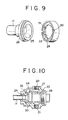
- the atomized water generator 22 consists of a disk 24 having a circular recess 23 and a conical hole 25 with its diameter gradually decreasing from that corresponding to said recess. Further, a cylinder 26 having the same diameter as that of said disk 24 is coaxially fitted to said disk to form integrally with each other and then built in a housing 27. The disk 24 is surely pressed by a plug 28 and the cylinder 26 is connected to the additive water transfer tube 17. When the disk is fitted to the cylinder, an atomized water generating chamber 29 is formed.
- Grooves 30 and 31 for introducing the pressurized gas and the additive water and communicating to said recess 23 in the tangential direction thereof are provided on one plain perpendicular to the center axis at the end face of the disk 24 near the cylinder 26. These grooves are connected to the pressurized gas supply tube 20 and the additive water supply tube 21_respectively.
- the second embodiment of the present invention is a combination of the first embodiment and atomized water injection.
- the fuel gas supplied to the gas burner 1 through the connection 4 is ejected from the divergent flame type nozzzle 3a into the combustion tube 2.
- the jetted fuel gas mixes with the primary air C1 which flows through the inlet 6 and is swirled by the primary air swirling vanes 10 before being burnt in reduced primary combustion at the high heat load. Then, the primary combustion gas issues from the combustion tube 2 similarly to the first embodiment noted above.
- the secondary air C 2 throttled by the air damper 7 as shown in Fig. 1 to be at a required ratio with respect to the primary air C 1 is fed through the annular passage between the combustion tube 2 and the radiant tube 12 while cooling said combustion tube 2 and then flows along the inside of the radiant tube.
- the atomized water is obtained by the atomized water generator 18 as shown in Figs. 10 and 11, being injected from the water spray nozzle 18 located at the center of the divergent flame type nozzle 3a, thereby reducing the flame temperature to restrain the generation of NOx.
- bubbles of the atomized water is sharply expanded to blow up through injection due to the differential pressure across the bubbles and the combustion tube. Since the thickness of the bubble is very thin, i.e., 0.1 ⁇ m or above, the pieces of the blown-up bubbles are very fine. Therefore, the fine water particles will quickly absorb the latent heat from the flame, thereby greatly reducing the generation of NOx due to the lowered flame temperature.
- Figs. 12 and 13 refer to the corresponding parts which are the same as illustrated in Figs. 7 and 8. However, it differs from the second embodiment in such a point that the exhaust gas is ejected into the center of the fuel gas as atomizing medium while in the second embodiment water is used as atomizing medium.
- the mechanism of the radiant tube burner in the third embodiment of the present invention is similar to that of the second embodiment with only such difference that the nozzle is constituted as a divergent flame type nozzle 3b, the description thereof will be omitted.
- Fig. 14 shows a modification of the third embodiment of the present invention which is related to the atomizing system due to low pressure fuel gas.
- the gas burner 1 is placed coaxially with the combustion tube 2.
- the divergent flame type nozzle 3b is provided at the front end of the burner 1.
- a water outflow nozzle 32 is provided at the center of the nozzle 3b.
- gas swirling vanes 33 having an angle within the range from 15 to 40°.
- the operating mechanism of the radiant tube burner of the modification of the third embodiment employing the atomizing system with low pressure fuel gas will be described in the following.
- the gas G introduced into the gas burner 1 from the gas connection 4 is fed in the direction shown by the arrow to be swirled at high speed by the gas swirling vanes 33, while the water W introduced into the additive water transfer tube 17 (See Figs. 12 and 13) connected to an additive water connection port 36 is fed in the direction shown by an arrow to issue from the water outflow nozzle 32.
- the water discharged from the water outflow nozzle is atomized by the velocity energy of the fuel gas.
- the atomized water and fuel gas are sufficiently mixed with each other and the effect of water addition is greatly enhanced.
- Figs. 14 and 15 show a modification of the third embodiment of the present invention which is related to the atomizing system with low pressure exhaust gas.
- an exhaust gas introducing tube 34 for atomizing the water supplied from the water outflow nozzle 32 is placed at the center of the divergent flame type nozzle 3b.
- the additive water transfer tube 17 is placed at the center of the introducing tube 34.
- exhaust gas swirling vanes 35 having an angle within the range from 15 to 40°.
- the exhaust gas G' is swirled at high speed by the exhaust gas swirling vanes 35 to atomize the water W discharged from the water outflow nozzle 32.
- the atomized water is mixed with the fuel gas G (WG) supplied from the divergent flame type nozzle 3b by the high speed swirling flow of the exhaust gas. Therefore, the mixing of the exhaust gas and the fuel gas and that of the fuel gas and the atomized water occur rapidly to reduce the flame temperature by making the flame temperature uniform due to the combustion delay of the fuel gas and absorption of the latent heat by the atomized water, thereby greatly reducing the generation of NOx.
- the radiant tube burner including two modifications of the third embodiment noted above has two ways of water atomizing system.
- One is using pressurized gas (air, vapor and inert gas) within the range from 2 to 6 kg/cm 2 and the other is using low pressure gas (fuel gas, exhaust gas or the like) with the range from 300 to 1,000 mm AG.
- NOx reduction rate by adding water in the radiant tube burner according to the present invention including the third and fourth embodiments is represented by the relation between the amount of additive water and the NOx reduction rate as shown in Fig. 16.
- the radiant tube burner according to the present invention will give utmost effectiveness when used for a furnace in which direct exposure of workpieces to waste gas is not desirable. i.e., non-oxidation furnaces, heat treatment furnaces and the like utilizing atmospheric gas and indirect heating system in which workpieces and waste gas should not come in contact.
- Applicable fields will include those industries such as metalworking industry, ceramics, glass industry, chemical industry, paper and fiber industry and food industry or the like.
Abstract
Description
- This invention relates to a radiant tube burner in which a nozzle of a gas burner is coaxially placed in a combustion tube located in a radiant tube so that the burner can be moved in the axial direction, fuel gas issuing from the gas burner undergoes primary combustion by primary air supplied through the annular space between the gas burner and the combustion tube and further undergoes secondary combustion by secondary air supplied through the annular space between the combustion tube and the radiant tube and, more particularly to a radiant tube burner used for heat treatment furnaces or the like. The newly invented burner is capable of reducing the amount of NOx contained in the exhaust gas discharged from the radiant tube.
- There has been a proposal in the design of radiant tube burners in which a damper is provided at the inlet of the primary air admitted into the combustion tube, for example, to restrain the generation of NOx, thereby making it possible to change the primary and the secondary air ratio.. (See Japanese Utility Model Laid-open No. Sho 52-21036)
- However, it has been found out that the amount of generated Nox cannot be sufficiently reduced only by adjusting the primary and the secondary air ratio.
- Further, there has been known another proposal in which a steam tube is provided in the fuel gas nozzle to eject steam into the flame formed by burner combustion, to make it possible to reduce the flame temperature to restrain the generation of NOx (See Japanese Patent Laid-open No. Sho 52-29007).
- When comparing the case of ejecting steam with that of atomizing water, the latter is more effective in reducing the flame temperature, thus leading to higher reduction of Nox. However, an adverse effect on the radiant tube and instability of the flame may be expected due to the relatively large particle size of atomized water so that the practical use has been considered to be impossible.
- It is an object of the present invention to provide a radiant tube burner in which high heat load primary combustion is caused to happen in satisfactory and stable way by swirling the primary air and soft secondary combustion takes place in a radiant tube, thereby making it possible to obtain low NOx.
- In order to attain the first object, according to the present invention, a divergent flame type nozle is installed movably in the axial direction, while swirling vanes are provided on the outer periphery thereof and air dampers for adjusting the primary and the secondary air ratio is provided on the outside of a primary air supply tube.
- Another object of the present invention is to provide a radiant tube burner in which the flame temperature is reduced by means of adding atomized water into the combustion flame, thereby making it possible to obtain low NOx, while high heat load combustion is going on in satisfactory and stable way owing to the two-stage combustion descirbed above.
- In order to attain the second object, a water spray nozzle is placed at the center of the divergent flame type nozzle, said nozzle being connected to an atomized water generator capable of supplying pressurized gas and additive water through an additive water transfer tube installed in the gas burner.
- Further, as a different advantageous means according to the present invention, the atomized water generator is composed of a cylinder having a conical hole to be connected to the additive water transfer tube, a recessed disk having grooves for injecting pressurized gas and additive water thereinto and fitted to said cylinder and a housing for accommodating said cylinder and said disk.
- It is also another object of the present invention to provide a radiant tube burner in which, in addition to the aforementioned features, the exhaust gas is used as atomizing medium, thereby accomplishing enhanced reduction of NOx while high heat load and low NOx combustion occurs due to the swirling of the primary air and addition of atomized water into the combustion flame.
- In order to attain the third object, the atomized water generator is connected to the exhaust gas pipe, while other parts remain the same as described in the second object.
- Further, as another advantageous means to materialize the object of the invention, low pressure fuel gas can be used as atomizing medium. In this case, the water atomizer is connected to the fuel gas while other parts remain the same as described in the second object.
- In addition, as another advantageous means, an exhaust gas introducing tube and a water out-flow nozzle are placed at the central portion of the divergent flame tube nozzle to utilize the velocity energy of low pressure exhaust gas to atomize the water supplied from the additive water transfer tube.
- The above-mentioned objects and features of this invention will be evident from the following description presented in reference to the drawings which indicate embodiments of the invention.
-
- Fig. 1 is a longitudinal sectional view showing an embodiment of the radiant tube burner according to the present invention;
- Figs. 2 and 3 are a front view and a sectional view showing the divergent flame type nozzle in the burner of the present invention;
- Figs. 4 and 5 are a longitudinal sectional view and a front view showing primary air swirling vanes in the burner of the present invention;
- Fig. 6 shows the amount of generated NOx versus the maximum temperature of the radiant tube for explaining the effect of NOx reduction in the radiant tube burner according to the present invention;
- Fig. 7 is a longitudinal sectional view showing a second embodiment of the radiant tube burner according to the present invention;
- Fig. 8 is a longitudinal sectional view showing the divergent flame type nozzle used in the burner of the present invention;
- Figs. 9 and 10 are a fragmentary exploded perspective view and an assembled sectional view showing the atomized water generator in the burner of the present invention.
- Fig. 11 explains the mechanism of atomized water generation;
- Fig. 12 is a longitudinal sectional view showing a third embodiment of the radiant tube burner·according to the present invention;
- Fig. 13 is a longitudinal sectional view showing the divergent flame type nozzle in the burner of the present invention;
- Fig. 14 is a view, partially cross-section, showing a major portion of a fourth embodiment of the radiant tube burner according to the present invention using the water atomizing system with low pressure fuel gas;
- Fig. 15 is a view, partially cross-section, showing a major portion of a fifth embodiment of the radiant tube burner according to the present invention adopting the atomized water system by low pressure exhaust gas; and
- Fig. 16 shows the amount of additive water versus the reduction rate of NOx in the radiant tube burner according to the present invention.
- Referring to Fig. 1 showing the first embodiment, a
gas burner 1 is coaxially placed with acombustion tube 2. A divergentflame type nozzle 3a (see Figs. 2 and 3) is mounted at the end of theburner 1. At the rear end of theburner 1, there is afuel gas connection 4. A primaryair supply tube 5 joins the rear end of thecombustion tube 2 to form an integral piece extending coaxially with theburner 1. The primaryair supply tube 5 has fourrectangular ports 6 evenly spaced over the entire periphery thereof. The area of theinlet 6 can be changed by moving, with anoperating rod 8 and anut 9, acylindrical air damper 7, into which theair supply tube 5 is loosely fitted. Primaryair swirling vanes 10 having an angle within the range from 15 to 60° are secured on aretaining tube 11 at the front end of saidburner 1, as shown in Figs. 4 and 5. Thecombustion tube 2 and the primaryair supply tube 5 are coaxially housed in aradiant tube 12. Anair supply connection 13 is provided at the rear section of theradiant tube 12 in which theinlet ports 6 are located. Anend cover 14 closes rear ends of the primaryair supply tube 5 andradiant tube 12. Thegas burner 1 is installed across saidend cover 14 to extend rearward.Reference numeral 15 designates a pilot burner. Thegas burner 1 extends movably through theend cover 14 in the axial direction within the range of thecombustion tube 2 together with thepilot burner 15. Accordingly, the divergentflame type nozzle 3a is supported in thecombustion tube 2 through theswirling vanes 10 so that the nozzle position is changeable. - The set position L of the divergent
flame type nozzle 3a is changeable within the range from 100 to 500 mm. Theburner 1 is fixed by abolt 16 attached on theend cover 14. - Next, the operating mechanism of the radiant tube burner according to the first embodiment of the present invention will be described in the following. Referring to Fig. 1, the gas supplied to the
gas burner 1 through theconnection 4 is ejected from the divergentflame type nozzle 3a into thecombustion tube 2 at the maximum ejection angle of 60° and at the speed ranging from 10 to 100 m/sec. The jetted fuel gas mixes with primary air C1 which flows through theinlet 6 and is swirled by theswirling vanes 10 before being burnt in reduced primary combustion at the high heat load within the range from 500 x 104 kcal/m3-h 1,000 x 104 kcal/m3-h. The primary combustion gas issues from thecombustion tube 2 in the axial direction into theradiant tube 12 at the speed within the range from 10 to 30 m/sec. Secondary air C2 (90 to 50%) throttled by theair damper 7 to be at a required ratio with respect to the primary air C1 (10 to 50%) is fed through the annular passage between thecombustion tube 2 and theradiant tube 12 while cooling saidcombustion tube 2 at a speed slower than that of the primary combustion gas. The secondary air C2 flows along the inside of theradiant tube 12 due to the kinetic energy differential between the secondary air C2 and the primary combustion gas, while making the secondary combustion occur in less concentrated way to prevent localized heating at the boundary against the primary combustion gas, thereby controlling the generation of NOx. - Test result with a 7 inch (17.5 cm) radiant tube burner according to the first embodiment of the present invention are as follows. The heat rate was as much as 145,000 kcal/h while generally accepted limit had been 110,000 kcal/h with prior art. NOx may be reduced to 80 through 150 ppm by changing the position of the
nozzle 3a and the primary and the secondary air ratio. Furthermore, there was little soot and carbon monoxide even under the stringent condition where the residual 02 in the exhaust gas was less than one percent. It is also possible to obtain turn-down ratio less than 10% down to which stable combustion can be performed without blowout even when combustion air flow capacity is held at 100% and fuel gas is throttled down to 10%. - Regarding the tube temperature, which is an important factor in the operation of radiant tube burners, it is possible to obtain uniform tube temperature due to the rotation of the flame, with the temperature change in the circumferential direction within 10°C. Further, the temperature difference in the axial direction between the maximum and the minimum in the furnace is made within 150°C, so that extended tube life can be expected.
- Fig. 6 shows the maximum temperature of the radiant tube versus the amount of generation of NOx to explain the effect of NOx reduction according to the present invention. It is obvious that NOx can be reduced by approximately 30% compared with a prior art radiant tube burner.
- Next, the second embodiment according to the present invention is described in the following with reference to Fig. 7. The numbers in Fig. 7 refer to the corresponding parts which are the same as illustrated in Fig. 1.
- Referring to Figs. 7 and 8, the
gas burner 1 is placed coaxially with thecombustion tube 2. The divergentflame type nozzle 3a is mounted at the end of theburner 1. At the rear end of theburner 1, there is thefuel gas connection 4. The primaryair supply tube 5 joins the rear end of thecombustion tube 2 to form an integral piece extending coaxially with theburner 1. The primaryair supply tube 5 has fourrectangular ports 6 evenly spaced over the entire periphery thereof. The primaryair swirling vanes 10 having an angle within the range from 15 to 60° are secured on a retaining tube (not shown) at the end of saidburner 1. Thecombustion tube 2 and the primaryair supply tube 5 are coaxially housed in theradiant tube 12. The primary air supply tube and the radiant tube are closed by the end cover through flanges respectively. Further, thegas burner 1 is installed across the end cover to extend rearward. - A
water spray nozzle 18 communicating to an additivewater transfer tube 17 placed in saidgas burner 1 is provided at the center of the divergentflame type nozzle 3a and a multiple number ofgas injection ports 14 communicating to thegas connection 4 are provided around saidnozzle 18 as shown in Fig. 8. Further, anair supply connection 13 is connected to the rear section of theradiant tube 12. Anatomized water generator 22 connected to thepressurized gas tube 20 and the additivewater transfer tube 21 is at its rear end. - Referring to Figs. 9 and 10, the atomized
water generator 22 consists of adisk 24 having acircular recess 23 and aconical hole 25 with its diameter gradually decreasing from that corresponding to said recess. Further, acylinder 26 having the same diameter as that of saiddisk 24 is coaxially fitted to said disk to form integrally with each other and then built in ahousing 27. Thedisk 24 is surely pressed by aplug 28 and thecylinder 26 is connected to the additivewater transfer tube 17. When the disk is fitted to the cylinder, an atomizedwater generating chamber 29 is formed.Grooves recess 23 in the tangential direction thereof are provided on one plain perpendicular to the center axis at the end face of thedisk 24 near thecylinder 26. These grooves are connected to the pressurizedgas supply tube 20 and the additive water supply tube 21_respectively. - The second embodiment of the present invention is a combination of the first embodiment and atomized water injection. For ease of understanding explanation on the air and the gas flow will be repeated. Referring to Fig. 7, the fuel gas supplied to the
gas burner 1 through theconnection 4 is ejected from the divergentflame type nozzzle 3a into thecombustion tube 2. The jetted fuel gas mixes with the primary air C1 which flows through theinlet 6 and is swirled by the primaryair swirling vanes 10 before being burnt in reduced primary combustion at the high heat load. Then, the primary combustion gas issues from thecombustion tube 2 similarly to the first embodiment noted above. - On the other hand, the secondary air C2 throttled by the
air damper 7 as shown in Fig. 1 to be at a required ratio with respect to the primary air C1 is fed through the annular passage between thecombustion tube 2 and theradiant tube 12 while cooling saidcombustion tube 2 and then flows along the inside of the radiant tube. Thus, the secondary combustion successively occurs to prevent localized heating at the boundary against the primary combustion gas. The atomized water is obtained by the atomizedwater generator 18 as shown in Figs. 10 and 11, being injected from thewater spray nozzle 18 located at the center of the divergentflame type nozzle 3a, thereby reducing the flame temperature to restrain the generation of NOx. In this case, bubbles of the atomized water is sharply expanded to blow up through injection due to the differential pressure across the bubbles and the combustion tube. Since the thickness of the bubble is very thin, i.e., 0.1µ m or above, the pieces of the blown-up bubbles are very fine. Therefore, the fine water particles will quickly absorb the latent heat from the flame, thereby greatly reducing the generation of NOx due to the lowered flame temperature. - Next, the third embodiment of the radiant tube burner according to the present invention will be described with reference to Figs. 12 and 13. The number in Figs. 12 and 13 refer to the corresponding parts which are the same as illustrated in Figs. 7 and 8. However, it differs from the second embodiment in such a point that the exhaust gas is ejected into the center of the fuel gas as atomizing medium while in the second embodiment water is used as atomizing medium.
- Since the mechanism of the radiant tube burner in the third embodiment of the present invention is similar to that of the second embodiment with only such difference that the nozzle is constituted as a divergent
flame type nozzle 3b, the description thereof will be omitted. - Next, Fig. 14 shows a modification of the third embodiment of the present invention which is related to the atomizing system due to low pressure fuel gas. As shown in Fig. 14, the
gas burner 1 is placed coaxially with thecombustion tube 2. The divergentflame type nozzle 3b is provided at the front end of theburner 1. Awater outflow nozzle 32 is provided at the center of thenozzle 3b. In the annular space defined by the water outflow nozzle and the exhaust gas nozzle are installedgas swirling vanes 33 having an angle within the range from 15 to 40°. - Next, the operating mechanism of the radiant tube burner of the modification of the third embodiment employing the atomizing system with low pressure fuel gas will be described in the following. As shown in Fig. 14, the gas G introduced into the
gas burner 1 from thegas connection 4 is fed in the direction shown by the arrow to be swirled at high speed by thegas swirling vanes 33, while the water W introduced into the additive water transfer tube 17 (See Figs. 12 and 13) connected to an additivewater connection port 36 is fed in the direction shown by an arrow to issue from thewater outflow nozzle 32. In this case, the water discharged from the water outflow nozzle is atomized by the velocity energy of the fuel gas. - Thus, since the water is atomized by the velocity energy of the fuel gas, the atomized water and fuel gas are sufficiently mixed with each other and the effect of water addition is greatly enhanced.
- Figs. 14 and 15 show a modification of the third embodiment of the present invention which is related to the atomizing system with low pressure exhaust gas. As shown in the figures, an exhaust
gas introducing tube 34 for atomizing the water supplied from thewater outflow nozzle 32 is placed at the center of the divergentflame type nozzle 3b. The additivewater transfer tube 17 is placed at the center of the introducingtube 34. In the annular space defined by the water outflow nozzle and the exhaust gas nozzle are provided exhaustgas swirling vanes 35 having an angle within the range from 15 to 40°. - The mechanism of the radiant tube burner of the modification of the third embodiment employing the atomizing system with the low pressure exhaust gas will be described in the following. As shown in Fig. 15, the exhaust gas G' is swirled at high speed by the exhaust
gas swirling vanes 35 to atomize the water W discharged from thewater outflow nozzle 32. The atomized water is mixed with the fuel gas G (WG) supplied from the divergentflame type nozzle 3b by the high speed swirling flow of the exhaust gas. Therefore, the mixing of the exhaust gas and the fuel gas and that of the fuel gas and the atomized water occur rapidly to reduce the flame temperature by making the flame temperature uniform due to the combustion delay of the fuel gas and absorption of the latent heat by the atomized water, thereby greatly reducing the generation of NOx. - The radiant tube burner including two modifications of the third embodiment noted above has two ways of water atomizing system. One is using pressurized gas (air, vapor and inert gas) within the range from 2 to 6 kg/cm2 and the other is using low pressure gas (fuel gas, exhaust gas or the like) with the range from 300 to 1,000 mm AG.
- NOx reduction rate by adding water in the radiant tube burner according to the present invention including the third and fourth embodiments is represented by the relation between the amount of additive water and the NOx reduction rate as shown in Fig. 16.
- Operational factors of the radiant tube burner according to the present invention noted above are shown as follows:
- Fuel COG : 4,500 kcal/Nm
- calorific force : 145,000 kcal/h
- air temperature for combustion : 400°C
- Residual 02 contained in the exhaust gas : 4 %
- radiant tube type : 7 inch W type
- As is obvious from the result, NOx can be efficiently reduced by adding water in the radiant tube burner Furthermore, since the maximum tube temperature may be lowered, the extended tube life can be expected.>
- As has been described in the foregoing, the radiant tube burner according to the present invention will give utmost effectiveness when used for a furnace in which direct exposure of workpieces to waste gas is not desirable. i.e., non-oxidation furnaces, heat treatment furnaces and the like utilizing atmospheric gas and indirect heating system in which workpieces and waste gas should not come in contact. Applicable fields will include those industries such as metalworking industry, ceramics, glass industry, chemical industry, paper and fiber industry and food industry or the like.
where, the amount of additive water is gradually increased to obtain higher NOx reduction rate (%).
Claims (8)
Priority Applications (1)
| Application Number | Priority Date | Filing Date | Title |
|---|---|---|---|
| AT86906451T ATE56520T1 (en) | 1985-10-31 | 1986-10-30 | RADIANT TUBE BURNER. |
Applications Claiming Priority (8)
| Application Number | Priority Date | Filing Date | Title |
|---|---|---|---|
| JP242930/85 | 1985-10-31 | ||
| JP24293085 | 1985-10-31 | ||
| JP26734885 | 1985-11-29 | ||
| JP267348/85 | 1985-11-29 | ||
| JP237016/86 | 1986-10-07 | ||
| JP237017/86 | 1986-10-07 | ||
| JP23701686A JPS62190311A (en) | 1985-10-31 | 1986-10-07 | Radiant tube burner |
| JP23701786A JPS62242711A (en) | 1985-11-29 | 1986-10-07 | Radiant tube burner |
Publications (3)
| Publication Number | Publication Date |
|---|---|
| EP0243506A1 true EP0243506A1 (en) | 1987-11-04 |
| EP0243506A4 EP0243506A4 (en) | 1989-01-24 |
| EP0243506B1 EP0243506B1 (en) | 1990-09-12 |
Family
ID=27477683
Family Applications (1)
| Application Number | Title | Priority Date | Filing Date |
|---|---|---|---|
| EP86906451A Expired - Lifetime EP0243506B1 (en) | 1985-10-31 | 1986-10-30 | Radiant tube burner |
Country Status (4)
| Country | Link |
|---|---|
| EP (1) | EP0243506B1 (en) |
| AU (1) | AU573109B2 (en) |
| DE (1) | DE3674198D1 (en) |
| WO (1) | WO1987002756A1 (en) |
Cited By (10)
| Publication number | Priority date | Publication date | Assignee | Title |
|---|---|---|---|---|
| EP0435735A1 (en) * | 1989-12-28 | 1991-07-03 | Institut Français du Pétrole | Industrial, liquid-fuel burner with low nitrogen oxide emissions, said burner generating several individual flames, and its use |
| EP0455459A2 (en) * | 1990-05-01 | 1991-11-06 | General Electric Company | Combustion method and apparatus |
| WO1992005390A1 (en) * | 1990-09-14 | 1992-04-02 | Solar Turbines Incorporated | A gaseous fuel injector |
| EP0543324A2 (en) * | 1991-11-22 | 1993-05-26 | Aichelin Gmbh | Burner for industrial furnaces |
| US5513981A (en) * | 1991-11-22 | 1996-05-07 | Aichelin Gmbh | Burner with variable volume combination chamber |
| WO1998023901A1 (en) * | 1996-11-26 | 1998-06-04 | Teollisuuslämpö Oy | Combustion apparatus for gases |
| EP0849526A3 (en) * | 1996-12-20 | 1999-07-07 | IPEG S.p.A. dell'Ing. Mauro Poppi | High heat release burner |
| EP1422473A1 (en) * | 2002-11-21 | 2004-05-26 | Hauck Manufacturing Company | U-tube diffusion flame burner assembly having unique flame stabilization |
| ITVE20110067A1 (en) * | 2011-10-06 | 2013-04-07 | Foinox S P A | HEAT EXCHANGER FOR GAS COOKING APPLIANCES. |
| ITVE20110066A1 (en) * | 2011-10-06 | 2013-04-07 | Foinox S P A | HEAT EXCHANGER FOR GAS COOKING APPLIANCES. |
Citations (2)
| Publication number | Priority date | Publication date | Assignee | Title |
|---|---|---|---|---|
| JPS5560104A (en) * | 1978-10-30 | 1980-05-07 | Nippon Steel Corp | Two-stage combustion burner for radiant tube |
| EP0117029A1 (en) * | 1983-01-18 | 1984-08-29 | W.B. Combustion Limited | Single-ended radiant tube |
Family Cites Families (10)
| Publication number | Priority date | Publication date | Assignee | Title |
|---|---|---|---|---|
| JPS5218929B2 (en) * | 1973-01-18 | 1977-05-25 | ||
| JPS5070929A (en) * | 1973-10-24 | 1975-06-12 | ||
| JPS5240451B2 (en) * | 1974-02-06 | 1977-10-12 | ||
| JPS5229007B2 (en) * | 1974-05-27 | 1977-07-29 | ||
| JPS5156028A (en) * | 1974-11-12 | 1976-05-17 | Nippon Kokan Kk | CHITSUSOSANKABUTSUYOKUSEIHOHO |
| JPS5221036U (en) * | 1975-08-02 | 1977-02-15 | ||
| JPS5222132A (en) * | 1975-08-07 | 1977-02-19 | Daido Steel Co Ltd | Burner combustion method and apparatus with addition of water |
| JPS57166410A (en) * | 1981-04-03 | 1982-10-13 | Maruzen Eng Kk | Water injection combustion method and water injection combustion burner |
| JPS5942427U (en) * | 1982-09-10 | 1984-03-19 | 東京瓦斯株式会社 | Double tube type radiant tube |
| JPS60218519A (en) * | 1984-04-13 | 1985-11-01 | Nippon Nenshiyou Syst Kk | Multi-fuel combustion burner |
-
1986
- 1986-10-30 EP EP86906451A patent/EP0243506B1/en not_active Expired - Lifetime
- 1986-10-30 AU AU65940/86A patent/AU573109B2/en not_active Ceased
- 1986-10-30 WO PCT/JP1986/000550 patent/WO1987002756A1/en active IP Right Grant
- 1986-10-30 DE DE8686906451T patent/DE3674198D1/en not_active Expired - Lifetime
Patent Citations (2)
| Publication number | Priority date | Publication date | Assignee | Title |
|---|---|---|---|---|
| JPS5560104A (en) * | 1978-10-30 | 1980-05-07 | Nippon Steel Corp | Two-stage combustion burner for radiant tube |
| EP0117029A1 (en) * | 1983-01-18 | 1984-08-29 | W.B. Combustion Limited | Single-ended radiant tube |
Non-Patent Citations (2)
| Title |
|---|
| PATENT ABSTRACTS OF JAPAN, vol. 4, no. 102 (M-22)[584], 22nd July 1980; & JP-A-55 060 104 (SHIN NIPPON SEITETSU K.K.) 07-05-1980 * |
| See also references of WO8702756A1 * |
Cited By (14)
| Publication number | Priority date | Publication date | Assignee | Title |
|---|---|---|---|---|
| EP0435735A1 (en) * | 1989-12-28 | 1991-07-03 | Institut Français du Pétrole | Industrial, liquid-fuel burner with low nitrogen oxide emissions, said burner generating several individual flames, and its use |
| FR2656676A1 (en) * | 1989-12-28 | 1991-07-05 | Inst Francais Du Petrole | INDUSTRIAL BURNER WITH LIQUID FUEL WITH LOW NITROGEN OXIDE EMISSION, THIS BURNER GENERATES MULTIPLE ELEMENTARY FLAMES AND ITS USE. |
| EP0455459A2 (en) * | 1990-05-01 | 1991-11-06 | General Electric Company | Combustion method and apparatus |
| EP0455459A3 (en) * | 1990-05-01 | 1992-04-08 | General Electric Company | Combustion method and apparatus |
| WO1992005390A1 (en) * | 1990-09-14 | 1992-04-02 | Solar Turbines Incorporated | A gaseous fuel injector |
| EP0543324A3 (en) * | 1991-11-22 | 1993-09-08 | Aichelin Gmbh | Burner for industrial furnaces |
| EP0543324A2 (en) * | 1991-11-22 | 1993-05-26 | Aichelin Gmbh | Burner for industrial furnaces |
| US5513981A (en) * | 1991-11-22 | 1996-05-07 | Aichelin Gmbh | Burner with variable volume combination chamber |
| WO1998023901A1 (en) * | 1996-11-26 | 1998-06-04 | Teollisuuslämpö Oy | Combustion apparatus for gases |
| EP0849526A3 (en) * | 1996-12-20 | 1999-07-07 | IPEG S.p.A. dell'Ing. Mauro Poppi | High heat release burner |
| US6872070B2 (en) | 2001-05-10 | 2005-03-29 | Hauck Manufacturing Company | U-tube diffusion flame burner assembly having unique flame stabilization |
| EP1422473A1 (en) * | 2002-11-21 | 2004-05-26 | Hauck Manufacturing Company | U-tube diffusion flame burner assembly having unique flame stabilization |
| ITVE20110067A1 (en) * | 2011-10-06 | 2013-04-07 | Foinox S P A | HEAT EXCHANGER FOR GAS COOKING APPLIANCES. |
| ITVE20110066A1 (en) * | 2011-10-06 | 2013-04-07 | Foinox S P A | HEAT EXCHANGER FOR GAS COOKING APPLIANCES. |
Also Published As
| Publication number | Publication date |
|---|---|
| AU573109B2 (en) | 1988-05-26 |
| EP0243506A4 (en) | 1989-01-24 |
| EP0243506B1 (en) | 1990-09-12 |
| AU6594086A (en) | 1987-05-19 |
| WO1987002756A1 (en) | 1987-05-07 |
| DE3674198D1 (en) | 1990-10-18 |
Similar Documents
| Publication | Publication Date | Title |
|---|---|---|
| US4813867A (en) | Radiant tube burner | |
| CA2211769C (en) | Low emission swirl burner | |
| EP0690264B1 (en) | Pulverized coal burner | |
| KR100330675B1 (en) | Pulverized coal burner | |
| US5199355A (en) | Low nox short flame burner | |
| US4815966A (en) | Burner for burning liquid or gaseous fuels | |
| JPS63210508A (en) | Super low nox combustion device | |
| US4601428A (en) | Burner tip | |
| US4412808A (en) | Dual fueled burner gun | |
| JPH05256420A (en) | Swirling-flow burner | |
| JP2006029763A (en) | Multi-fuel burner | |
| EP0243506B1 (en) | Radiant tube burner | |
| CA1073337A (en) | Large burners, particularly for liquid fuels | |
| US4105393A (en) | Fuel burners | |
| JPH0252765B2 (en) | ||
| JPH06341611A (en) | Method and burner of minimally inhibiting quality of nox discharged from combustion | |
| US5685706A (en) | V-jet atomizer | |
| EP0165725B1 (en) | Low pressure loss burner for coal-water slurry or fuel oil | |
| JPH0474603B2 (en) | ||
| CA1286590C (en) | Radiant tube burner | |
| KR910001837B1 (en) | Radiant tube burner | |
| JP4420492B2 (en) | Liquid fuel burner and operation method thereof | |
| KR100246876B1 (en) | An improved burner operable from dual fuels supplied simultaneously or singly | |
| CA1282314C (en) | Radiant tube burner | |
| JPS63116011A (en) | Radiant tube burner |
Legal Events
| Date | Code | Title | Description |
|---|---|---|---|
| PUAI | Public reference made under article 153(3) epc to a published international application that has entered the european phase |
Free format text: ORIGINAL CODE: 0009012 |
|
| 17P | Request for examination filed |
Effective date: 19870616 |
|
| AK | Designated contracting states |
Kind code of ref document: A1 Designated state(s): AT BE CH DE FR GB IT LI LU NL SE |
|
| A4 | Supplementary search report drawn up and despatched |
Effective date: 19890124 |
|
| 17Q | First examination report despatched |
Effective date: 19890629 |
|
| GRAA | (expected) grant |
Free format text: ORIGINAL CODE: 0009210 |
|
| AK | Designated contracting states |
Kind code of ref document: B1 Designated state(s): AT BE CH DE FR GB IT LI LU NL SE |
|
| PG25 | Lapsed in a contracting state [announced via postgrant information from national office to epo] |
Ref country code: IT Free format text: LAPSE BECAUSE OF FAILURE TO SUBMIT A TRANSLATION OF THE DESCRIPTION OR TO PAY THE FEE WITHIN THE PRE;WARNING: LAPSES OF ITALIAN PATENTS WITH EFFECTIVE DATE BEFORE 2007 MAY HAVE OCCURRED AT ANY TIME BEFORE 2007. THE CORRECT EFFECTIVE DATE MAY BE DIFFERENT FROM THE ONE RECORDED.SCRIBED TIME-LIMIT Effective date: 19900912 Ref country code: LI Effective date: 19900912 Ref country code: SE Effective date: 19900912 Ref country code: AT Effective date: 19900912 Ref country code: CH Effective date: 19900912 Ref country code: NL Effective date: 19900912 |
|
| REF | Corresponds to: |
Ref document number: 56520 Country of ref document: AT Date of ref document: 19900915 Kind code of ref document: T |
|
| ET | Fr: translation filed | ||
| REF | Corresponds to: |
Ref document number: 3674198 Country of ref document: DE Date of ref document: 19901018 |
|
| PG25 | Lapsed in a contracting state [announced via postgrant information from national office to epo] |
Ref country code: LU Free format text: LAPSE BECAUSE OF NON-PAYMENT OF DUE FEES Effective date: 19901031 |
|
| REG | Reference to a national code |
Ref country code: CH Ref legal event code: PL |
|
| NLV1 | Nl: lapsed or annulled due to failure to fulfill the requirements of art. 29p and 29m of the patents act | ||
| PLBE | No opposition filed within time limit |
Free format text: ORIGINAL CODE: 0009261 |
|
| STAA | Information on the status of an ep patent application or granted ep patent |
Free format text: STATUS: NO OPPOSITION FILED WITHIN TIME LIMIT |
|
| 26N | No opposition filed | ||
| PGFP | Annual fee paid to national office [announced via postgrant information from national office to epo] |
Ref country code: GB Payment date: 19961018 Year of fee payment: 11 |
|
| PGFP | Annual fee paid to national office [announced via postgrant information from national office to epo] |
Ref country code: FR Payment date: 19961029 Year of fee payment: 11 |
|
| PGFP | Annual fee paid to national office [announced via postgrant information from national office to epo] |
Ref country code: BE Payment date: 19961118 Year of fee payment: 11 |
|
| PGFP | Annual fee paid to national office [announced via postgrant information from national office to epo] |
Ref country code: DE Payment date: 19961126 Year of fee payment: 11 |
|
| PG25 | Lapsed in a contracting state [announced via postgrant information from national office to epo] |
Ref country code: GB Free format text: LAPSE BECAUSE OF NON-PAYMENT OF DUE FEES Effective date: 19971030 |
|
| PG25 | Lapsed in a contracting state [announced via postgrant information from national office to epo] |
Ref country code: BE Free format text: LAPSE BECAUSE OF NON-PAYMENT OF DUE FEES Effective date: 19971031 Ref country code: FR Free format text: THE PATENT HAS BEEN ANNULLED BY A DECISION OF A NATIONAL AUTHORITY Effective date: 19971031 |
|
| BERE | Be: lapsed |
Owner name: NIHON NENSHO SYSTEM K.K. Effective date: 19971031 Owner name: KAWAZAKI SEITETSU K.K. Effective date: 19971031 Owner name: MITSUBISHI JUKOGYO K.K. Effective date: 19971031 |
|
| GBPC | Gb: european patent ceased through non-payment of renewal fee |
Effective date: 19971030 |
|
| PG25 | Lapsed in a contracting state [announced via postgrant information from national office to epo] |
Ref country code: DE Free format text: LAPSE BECAUSE OF NON-PAYMENT OF DUE FEES Effective date: 19980701 |
|
| REG | Reference to a national code |
Ref country code: FR Ref legal event code: ST |