EP0243500A1 - Joint for assembling of sieve elements - Google Patents
Joint for assembling of sieve elements Download PDFInfo
- Publication number
- EP0243500A1 EP0243500A1 EP86902292A EP86902292A EP0243500A1 EP 0243500 A1 EP0243500 A1 EP 0243500A1 EP 86902292 A EP86902292 A EP 86902292A EP 86902292 A EP86902292 A EP 86902292A EP 0243500 A1 EP0243500 A1 EP 0243500A1
- Authority
- EP
- European Patent Office
- Prior art keywords
- widening
- fixing
- support
- assembling
- joint
- Prior art date
- Legal status (The legal status is an assumption and is not a legal conclusion. Google has not performed a legal analysis and makes no representation as to the accuracy of the status listed.)
- Withdrawn
Links
- 238000005304 joining Methods 0.000 claims description 20
- 239000007787 solid Substances 0.000 claims description 5
- 238000005520 cutting process Methods 0.000 claims description 3
- 238000013016 damping Methods 0.000 claims description 3
- 239000000834 fixative Substances 0.000 abstract 5
- 230000035939 shock Effects 0.000 abstract 1
- 238000004519 manufacturing process Methods 0.000 description 1
- 238000003825 pressing Methods 0.000 description 1
- 230000008929 regeneration Effects 0.000 description 1
- 238000011069 regeneration method Methods 0.000 description 1
- 210000003813 thumb Anatomy 0.000 description 1
Images


Classifications
-
- B—PERFORMING OPERATIONS; TRANSPORTING
- B07—SEPARATING SOLIDS FROM SOLIDS; SORTING
- B07B—SEPARATING SOLIDS FROM SOLIDS BY SIEVING, SCREENING, SIFTING OR BY USING GAS CURRENTS; SEPARATING BY OTHER DRY METHODS APPLICABLE TO BULK MATERIAL, e.g. LOOSE ARTICLES FIT TO BE HANDLED LIKE BULK MATERIAL
- B07B1/00—Sieving, screening, sifting, or sorting solid materials using networks, gratings, grids, or the like
- B07B1/46—Constructional details of screens in general; Cleaning or heating of screens
- B07B1/4609—Constructional details of screens in general; Cleaning or heating of screens constructional details of screening surfaces or meshes
- B07B1/4645—Screening surfaces built up of modular elements
-
- F—MECHANICAL ENGINEERING; LIGHTING; HEATING; WEAPONS; BLASTING
- F16—ENGINEERING ELEMENTS AND UNITS; GENERAL MEASURES FOR PRODUCING AND MAINTAINING EFFECTIVE FUNCTIONING OF MACHINES OR INSTALLATIONS; THERMAL INSULATION IN GENERAL
- F16B—DEVICES FOR FASTENING OR SECURING CONSTRUCTIONAL ELEMENTS OR MACHINE PARTS TOGETHER, e.g. NAILS, BOLTS, CIRCLIPS, CLAMPS, CLIPS OR WEDGES; JOINTS OR JOINTING
- F16B19/00—Bolts without screw-thread; Pins, including deformable elements; Rivets
- F16B19/04—Rivets; Spigots or the like fastened by riveting
- F16B19/08—Hollow rivets; Multi-part rivets
- F16B19/10—Hollow rivets; Multi-part rivets fastened by expanding mechanically
- F16B19/1027—Multi-part rivets
- F16B19/1036—Blind rivets
- F16B19/1081—Blind rivets fastened by a drive-pin
-
- F—MECHANICAL ENGINEERING; LIGHTING; HEATING; WEAPONS; BLASTING
- F16—ENGINEERING ELEMENTS AND UNITS; GENERAL MEASURES FOR PRODUCING AND MAINTAINING EFFECTIVE FUNCTIONING OF MACHINES OR INSTALLATIONS; THERMAL INSULATION IN GENERAL
- F16B—DEVICES FOR FASTENING OR SECURING CONSTRUCTIONAL ELEMENTS OR MACHINE PARTS TOGETHER, e.g. NAILS, BOLTS, CIRCLIPS, CLAMPS, CLIPS OR WEDGES; JOINTS OR JOINTING
- F16B5/00—Joining sheets or plates, e.g. panels, to one another or to strips or bars parallel to them
- F16B5/06—Joining sheets or plates, e.g. panels, to one another or to strips or bars parallel to them by means of clamps or clips
- F16B5/0685—Joining sheets or plates to strips or bars
-
- Y—GENERAL TAGGING OF NEW TECHNOLOGICAL DEVELOPMENTS; GENERAL TAGGING OF CROSS-SECTIONAL TECHNOLOGIES SPANNING OVER SEVERAL SECTIONS OF THE IPC; TECHNICAL SUBJECTS COVERED BY FORMER USPC CROSS-REFERENCE ART COLLECTIONS [XRACs] AND DIGESTS
- Y10—TECHNICAL SUBJECTS COVERED BY FORMER USPC
- Y10T—TECHNICAL SUBJECTS COVERED BY FORMER US CLASSIFICATION
- Y10T403/00—Joints and connections
- Y10T403/75—Joints and connections having a joining piece extending through aligned openings in plural members
Definitions
- the invention refers to a joint for assembling of sieve elements and more particulary for assembling of sieve elements with a gridiron of shakers, and finds application in the ore manufacturing industry, in the building and metalurgy.
- a known mash screen whose sieve elements are fitted to by means of the type described above in registered Bulgarian Pat.N .
- This joint assembling sieve elements consists of a fixing collar, a securing pin and a joining support. There is a fixing widening at the one side of the fixing collar and a support widening at the other one, and a part of the cylindric body of the fixing collar is long slotted.
- the wall of the axial plug-hole of the fixing collar and the external surface of the securing pin are wave-like, formed of annular hollows and projections in close succession.
- the invention has the object of designing a joint for assembling of sieve elements, ensuring a quick and easy detachment of the sieve elements from the gridiron of the shaker, whereupon the sieve elements do not damage.
- the objective is attained by means of a joint assembling sieve elements, consisting of a fixing collar, securing pin and joining support with securing apertures.
- the fixing collar is with a fixing widening at the one side and with a support widening at the other one.
- the support widening and part of the cylindric body of the fixing collar is long-slotted.
- on the fixing widening and on a part of the cylindric body length is cut at least one long groove reaching to a bottomed long slot.
- the securing pin is with outside cylindric surface and can pass through an axial plug-hole of the fixing collar and through a securing aperture of the joining support, placed in its propping sector.
- the bottom of the longitudinal groove is placed between the inside part of the longitudinal groove and the axial plug-hole of the fixing collar.
- the bottom of the longitudinal groove reaches up to the outer surface of the cylindric body and the fixing widening has a solid ring.
- the particular advantages of the joint for assembling of sieve elements per invention are as follows:possibility of detachment of the sieve elements from the gridiron of the shaker; at dismounting the sieve elements do not deform nor break out, which enables a repeated use and regeneration.
- the sieve elements may be mounted on the gridiron of its both sides, the fixing collar and the securing pin may be placed either from above downwards or from down upwards.
- the joint for assembling sieve elements (1) with the gridiron of a shaker consists of a fixing collar(2), securing pin (3) and joining support (4).
- the fixing collar (2) consists of a cylindric body (5) with a supporting widening (6) .at the one side and a fixing widening (7) at the other one and an axial plug-hole (8).
- the diameter of the fixing widening (7) is equal to the support widening (6) and is greater than the diameter of the cylindric body (5).
- This groove does not reach down to the axial,plug-hole (8).
- the bottom (10) Between the inside part of the long groove (9) and the axial plug-hole (8) is shaped the bottom (10).
- the support widening (6) and through a part of the cylindric body(5) is cut at least one long slotted hole (11), its width being equal at least to the width of the longitudinal groove (9).
- the beginning of the long-slotted cut (11) coincides with the end of the longitudinal groove (9), and its end reaches to the outer surface of the support widening (6).
- the total width of the longitudinal cuts (11) exceeds times the difference in the diameters between the support widening (6) and the cylindric body (5).
- On the outer surface of the fixing widening (7) are shaped longitudinal cogs (12).
- the securing pin (3) is with a cylindric surface, the outer diameter being bigger than the diameter of the axial plug-hole (8) of the fixing collar (2).
- the longitudinal grooves (9) of the fixing collar (2) are cut, on the surface of the axial plug-hole (8), their bottoms (10) reaching to the outer surface of the cylindric body (5).
- the fixing widening (7) is with a solid ring (13). Between same and the outer part of the fixing widening (7) there is first cylindric hollow (14). Between the solid ring (13) and the outer part of the fixing widening (7) there are radial holes (15) reaching to the beginning of the long grooves (9) of the cylindric body (5). At the end of the support widening (6) there is a second cylindric hollow (16).
- the securing pin (3) in this variation of the fixing collar (2) is at one side, following the mounting, with long protrusions (17) with cutting edges (18), whose number corresponds to the number of the long grooves (9) of the fixing collar (2).
- the joining support (4) consists of propping sector (19) with securing apertures (20) at both sides.
- the twin support (22) ends with two collateral fittings (23), but the single support (21) -with a middle fitting (24) which,when mounted, is placed between both end fittings (23) of the double support (22).
- the collateral fittings (23) and the middle fitting (24) end with a thumb oriented inwards, one facing the other.
- the single support (21) and the twin support (22) are fitted to the propping sector (19) by means of damping roundings (25) and at these places are made technological holes (26).
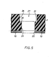
- every sieve element (1) is with cylindrically profiled holes (27) each of them two-staged with upper cylindric surface (28) and lower cylindric profile (29). Between the upper (28) and the lower cylindric surfaces (29) is formed a threshold (30) with a pressing inclined surface (31).
- the assembling of the sieve elements (1) may be done completely as well when proceeding from below of the gridiron.
- the sieve elements (1) are put on the propping sector (19) of the joining support (4) in the known way by meeting of their apertures.
- the fixing collar (2) are put at first by passing of each one through the securing apertures (20), the support widening (6) narrows in the long slotted cut (11) and passes consecutively through the securing apertures (20) and through the lower cylindric profile (29)of the cylindrically profiled hole (27).
- the support widening stretches and takes the space formed by the upper cylindric surface (28), and the fixing widening (7) touches from below the propping sector (19) in the range of the securing apertures (20).
- the securing pin (3) is driven into the axial hole from down upwards, whereupon it serves its known functions.
- the support widening (6) presses tight the upper cylindric part (28) of the cylindrically profiled hole (27), with exception of the places where the long slotted cuts (11) are made, hence the fixing collar (2) can not turn around its axis if at driving in of the securing pin (3) only one of the bottoms (10) breaks out. In this way it is effected a solid and reliable connection between the sieve elements (1) and the joining supports (4) which from their part are connected with the gridiron of the shaker.
- the dismounting of the sieve element (1) from the gridiron is effected by pulling out of the securing pin (3) from one of both sides, the easier for dismounting, and the fixing collar (2) which is split at the mounting from the driving in of the securing pin (2), is divided into parts equal in number to the long grooves (9), by which it liberates the cylindrically profiled hole (27) of the sieve element (1) and the securing aperture (20) of the joining support (4) which remains connected with the gridiron of the shaker.
- the joint element releases the worn-out sieve elements (1) from the gridiron without efforts and deformations.
Landscapes
- Engineering & Computer Science (AREA)
- General Engineering & Computer Science (AREA)
- Mechanical Engineering (AREA)
- Combined Means For Separation Of Solids (AREA)
- Nitrogen And Oxygen Or Sulfur-Condensed Heterocyclic Ring Systems (AREA)
Abstract
Description
- The invention refers to a joint for assembling of sieve elements and more particulary for assembling of sieve elements with a gridiron of shakers, and finds application in the ore manufacturing industry, in the building and metalurgy.
- A known mash screen whose sieve elements are fitted to by means of the type described above in registered Bulgarian Pat.N . This joint assembling sieve elements consists of a fixing collar, a securing pin and a joining support. There is a fixing widening at the one side of the fixing collar and a support widening at the other one, and a part of the cylindric body of the fixing collar is long slotted. The wall of the axial plug-hole of the fixing collar and the external surface of the securing pin are wave-like, formed of annular hollows and projections in close succession.
- The known realisation is associated with the disadvantage that it fits together sieve elements and gridiron in one piece, whereupon much time and efforts are needed for detaching them, because of the hard pulling out of the fixing collar from the securing apertures of the joining supports. Another disadvantage is the deforming and breaking out of the sieve element at dismounting.
- With a joint for assembling of sieve elements, consisting of a fixing collar, securing pin and a joining support, as a point of departure, the invention has the object of designing a joint for assembling of sieve elements, ensuring a quick and easy detachment of the sieve elements from the gridiron of the shaker, whereupon the sieve elements do not damage.
- The objective, according to the invention, is attained by means of a joint assembling sieve elements, consisting of a fixing collar, securing pin and joining support with securing apertures. The fixing collar is with a fixing widening at the one side and with a support widening at the other one. The support widening and part of the cylindric body of the fixing collar is long-slotted. According to the invention, on the fixing widening and on a part of the cylindric body length is cut at least one long groove reaching to a bottomed long slot. The securing pin is with outside cylindric surface and can pass through an axial plug-hole of the fixing collar and through a securing aperture of the joining support, placed in its propping sector. There are single and twin supports fitted to the propping sector by means of damping roundings. There are middle and collateral fittings at the lower end of the single and the twin supports respectively.
- According'to'a variation of the invention, the bottom of the longitudinal groove is placed between the inside part of the longitudinal groove and the axial plug-hole of the fixing collar. There are made longitudinal cogs on the outer surface of the fixing widening.
- According to another variation of the invention, the bottom of the longitudinal groove reaches up to the outer surface of the cylindric body and the fixing widening has a solid ring. There is a first cylindric hollow between the same and the outer surface of the fixing widening. There are long protrusions with cutting edges at the one side of the securing pin, following the assembling, whose number corresponds to the number of the longitudinal grooves of the fixing collar.
- The particular advantages of the joint for assembling of sieve elements per invention are as follows:possibility of detachment of the sieve elements from the gridiron of the shaker; at dismounting the sieve elements do not deform nor break out, which enables a repeated use and regeneration. In the first variation the sieve elements may be mounted on the gridiron of its both sides, the fixing collar and the securing pin may be placed either from above downwards or from down upwards.
-
- Figure 1 is a perspective view of a sieve with sieve elements, partially detached from the gridiron and an enlarged fixing collar and securing pin.
- Figure 2 is an axonometric figure of axial section of a fixing collar with outside longitudinal grooves.
- Figure 3 is an axonometric figure of axial section of a fixing collar with inside longitudinal grooves and securing pin.
- Figure 4 is a scheme of a joint mounted on a sieve element.
- Figure 5 is a side view of a cylindrically profiled aperture of a sieve element and securing apertures of a joining support.
- Figure 6 is an axonometric figure of a joining support on a gridiron.
- The invention will be explained in further details with the aid of explanatory embodiments as shown in the drawings.
- The joint for assembling sieve elements (1) with the gridiron of a shaker consists of a fixing collar(2), securing pin (3) and joining support (4). The fixing collar (2) consists of a cylindric body (5) with a supporting widening (6) .at the one side and a fixing widening (7) at the other one and an axial plug-hole (8). The diameter of the fixing widening (7) is equal to the support widening (6) and is greater than the diameter of the cylindric body (5). There is one long groove at least (9)cut on the outer surface of the fixing collar (2), as per Figure 2, on the fixing widening (7) and on a part length of the cylindric body (5). This groove does not reach down to the axial,plug-hole (8). Between the inside part of the long groove (9) and the axial plug-hole (8) is shaped the bottom (10). Through the support widening (6) and through a part of the cylindric body(5) is cut at least one long slotted hole (11), its width being equal at least to the width of the longitudinal groove (9).The beginning of the long-slotted cut (11) coincides with the end of the longitudinal groove (9), and its end reaches to the outer surface of the support widening (6). The total width of the longitudinal cuts (11) exceedstimes the difference in the diameters between the support widening (6) and the cylindric body (5). On the outer surface of the fixing widening (7) are shaped longitudinal cogs (12). The securing pin (3) is with a cylindric surface, the outer diameter being bigger than the diameter of the axial plug-hole (8) of the fixing collar (2).

- According to a variation shown on Figure 3, the longitudinal grooves (9) of the fixing collar (2) are cut, on the surface of the axial plug-hole (8), their bottoms (10) reaching to the outer surface of the cylindric body (5). The fixing widening (7) is with a solid ring (13). Between same and the outer part of the fixing widening (7) there is first cylindric hollow (14). Between the solid ring (13) and the outer part of the fixing widening (7) there are radial holes (15) reaching to the beginning of the long grooves (9) of the cylindric body (5). At the end of the support widening (6) there is a second cylindric hollow (16).
- The securing pin (3) in this variation of the fixing collar (2) is at one side, following the mounting, with long protrusions (17) with cutting edges (18), whose number corresponds to the number of the long grooves (9) of the fixing collar (2).
- The joining support (4) consists of propping sector (19) with securing apertures (20) at both sides. In the middle of the propping sector (19) unilaterally and vertically to it are placed separately one from another the single support (21) and the twin support (22). The twin support (22) ends with two collateral fittings (23), but the single support (21) -with a middle fitting (24) which,when mounted, is placed between both end fittings (23) of the double support (22). The collateral fittings (23) and the middle fitting (24) end with a thumb oriented inwards, one facing the other. The single support (21) and the twin support (22) are fitted to the propping sector (19) by means of damping roundings (25) and at these places are made technological holes (26).
- For assembling sieve element (1) with the gridiron every sieve element (1) is with cylindrically profiled holes (27) each of them two-staged with upper cylindric surface (28) and lower cylindric profile (29). Between the upper (28) and the lower cylindric surfaces (29) is formed a threshold (30) with a pressing inclined surface (31).
- The assembling of the sieve element with the gridiron with the help of the joint, as per invention, is executed in the following way:
- The sieve element (1) is placed on the gridiron so that to rest on the joining supports (4). The joining supports (4) are mounted on their places fixed on the gridiron. Their right positioning is found when the cylindrically profiled holes (27) fall in fully with the securing apertures (20) of the joining supports (4). The fixing collars (2) are put in each cylindrically profiled hole (27) of the sieve element (1), so that the support widening (6) of each fixing collar (2) passes consecutively through the lower cylindric profile (29) of the sieve element (1) and the securing apertures (20) of the joining support (4) with fold support widening (6) in the longitudinal slotted cut (11) of the support widening (6) through the securing apertures (20), the support widening (6) stretches and covers from the outer side through the securing apertures (20) the propping sector (19) of the joining supports (4), the longitudinal cogs (12) cut into the outer side(28) of the cylindrically profiled hole (27). The inner side of the fixing widening (7) presses the threshold (30) to the cylindrically profiled hole (27) increasing in this way the reliability of the joint and making tight connection between the sieve element (1) and the joining support (4). The securing pin (3) is driven into the axial plug-hole (8) of the fixing collar (2), as per Figure 2, from the side of the fixing widening (7) to the support widening (6) when mounting is executed from the upper side of the sieve elements (1) or from below from the support widening (6) to the fixing widening (7), when the mounting is executed from the downside of the sieve element (1). Because of the bigger diameter of the securing pin (3) compared with the diameter of the axial plug-hole (8), by driving in of the securing pin (3), the bottoms (10) of the long grooves break out and the fixing collar (2) is split into parts as many as the long grooves (9) are. The longitudinal cogs (12) do not permit to the fixing collar (2) to turn around its axis, if at driving in of the securing pin (3) only one from the bottoms (10) of the long grooves (9) is broken out.
- The assembling of the sieve elements (1) may be done completely as well when proceeding from below of the gridiron. The sieve elements (1) are put on the propping sector (19) of the joining support (4) in the known way by meeting of their apertures. The fixing collar (2) are put at first by passing of each one through the securing apertures (20), the support widening (6) narrows in the long slotted cut (11) and passes consecutively through the securing apertures (20) and through the lower cylindric profile (29)of the cylindrically profiled hole (27). Then the support widening stretches and takes the space formed by the upper cylindric surface (28), and the fixing widening (7) touches from below the propping sector (19) in the range of the securing apertures (20).The securing pin (3) is driven into the axial hole from down upwards, whereupon it serves its known functions. The support widening (6) presses tight the upper cylindric part (28) of the cylindrically profiled hole (27), with exception of the places where the long slotted cuts (11) are made, hence the fixing collar (2) can not turn around its axis if at driving in of the securing pin (3) only one of the bottoms (10) breaks out. In this way it is effected a solid and reliable connection between the sieve elements (1) and the joining supports (4) which from their part are connected with the gridiron of the shaker.
- The dismounting of the sieve element (1) from the gridiron is effected by pulling out of the securing pin (3) from one of both sides, the easier for dismounting, and the fixing collar (2) which is split at the mounting from the driving in of the securing pin (2), is divided into parts equal in number to the long grooves (9), by which it liberates the cylindrically profiled hole (27) of the sieve element (1) and the securing aperture (20) of the joining support (4) which remains connected with the gridiron of the shaker. The joint element releases the worn-out sieve elements (1) from the gridiron without efforts and deformations.
Claims (3)
Applications Claiming Priority (2)
| Application Number | Priority Date | Filing Date | Title |
|---|---|---|---|
| SU69366 | 1985-03-21 | ||
| BG8569366A BG41855A1 (en) | 1985-03-21 | 1985-03-21 | Connecting unit for mounting of screen elements |
Publications (1)
| Publication Number | Publication Date |
|---|---|
| EP0243500A1 true EP0243500A1 (en) | 1987-11-04 |
Family
ID=3915315
Family Applications (1)
| Application Number | Title | Priority Date | Filing Date |
|---|---|---|---|
| EP86902292A Withdrawn EP0243500A1 (en) | 1985-03-21 | 1986-03-19 | Joint for assembling of sieve elements |
Country Status (6)
| Country | Link |
|---|---|
| US (1) | US4990023A (en) |
| EP (1) | EP0243500A1 (en) |
| BG (1) | BG41855A1 (en) |
| HU (1) | HU199947B (en) |
| SU (1) | SU1569452A1 (en) |
| WO (1) | WO1986005559A1 (en) |
Cited By (4)
| Publication number | Priority date | Publication date | Assignee | Title |
|---|---|---|---|---|
| WO2000073669A1 (en) * | 1999-05-31 | 2000-12-07 | David Llewellen Owen | Screens |
| WO2003047771A1 (en) * | 2001-12-07 | 2003-06-12 | David Llewellyn Owen | Fastening means for screens |
| WO2003066243A1 (en) * | 2002-02-11 | 2003-08-14 | Multotec Manufacturing (Pty) Limited | Screen deck |
| CN107100918A (en) * | 2017-05-05 | 2017-08-29 | 中南林业科技大学 | Embedded connecting piece for hollow cellular board |
Families Citing this family (7)
| Publication number | Priority date | Publication date | Assignee | Title |
|---|---|---|---|---|
| US7841476B2 (en) * | 2004-09-27 | 2010-11-30 | Ludowici Australia Pty Ltd | Screening module retaining member |
| AU2005289353B2 (en) * | 2004-09-27 | 2010-01-28 | Flsmidth A/S | A screening module retaining member |
| AU2006243879B2 (en) * | 2006-11-28 | 2011-07-07 | Flsmidth A/S | A screening module retaining assembly |
| SE532358C2 (en) * | 2008-05-15 | 2009-12-22 | Sandvik Intellectual Property | Fixation of sight media |
| EP2610505A1 (en) * | 2011-12-30 | 2013-07-03 | AGUSTAWESTLAND S.p.A. | Insert of electrically conducting material, and tool and method for fitting such an insert to a supporting member |
| KR20150086498A (en) * | 2012-11-20 | 2015-07-28 | 테가 인더스트리즈 리미티드 | Snap fit fixing system for screen panels |
| EP3296029A1 (en) * | 2016-09-16 | 2018-03-21 | Metso Sweden Ab | Hammerless solution |
Family Cites Families (8)
| Publication number | Priority date | Publication date | Assignee | Title |
|---|---|---|---|---|
| US2402287A (en) * | 1943-09-27 | 1946-06-18 | Shellmar Products Corp | Plastic rivet |
| CH333422A (en) * | 1956-09-20 | 1958-10-31 | Fischer Artur | Device for fastening objects to masonry, concrete and the like |
| DE1212927B (en) * | 1964-07-02 | 1966-03-24 | Gewerk Eisenhuette Westfalia | Clamping element for connecting several sheet metal sheets one above the other or the like, preferably for connecting spring rails for hydraulic pit lining |
| GB1234524A (en) * | 1968-09-20 | 1971-06-03 | ||
| SU500384A1 (en) * | 1974-02-08 | 1976-01-25 | Станкостроительный Завод Имени Ильича | Lock for detachable connection of parts edges |
| US4405272A (en) * | 1981-03-11 | 1983-09-20 | Phillips Plastics Corporation | Two-piece fastener with front shoulder |
| SE8300121L (en) * | 1982-01-18 | 1983-07-19 | Inst Tech Kibernetik Robot | SIKTNET |
| FR2554522B1 (en) * | 1983-11-08 | 1986-04-18 | Renault | ASSEMBLY DEVICE |
-
1985
- 1985-03-21 US US07/008,508 patent/US4990023A/en not_active Expired - Fee Related
- 1985-03-21 BG BG8569366A patent/BG41855A1/en unknown
-
1986
- 1986-03-19 EP EP86902292A patent/EP0243500A1/en not_active Withdrawn
- 1986-03-19 WO PCT/BG1986/000003 patent/WO1986005559A1/en not_active Application Discontinuation
- 1986-03-19 HU HU862323A patent/HU199947B/en not_active IP Right Cessation
-
1987
- 1987-02-03 SU SU874028966A patent/SU1569452A1/en active
Non-Patent Citations (1)
| Title |
|---|
| See references of WO8605559A1 * |
Cited By (6)
| Publication number | Priority date | Publication date | Assignee | Title |
|---|---|---|---|---|
| WO2000073669A1 (en) * | 1999-05-31 | 2000-12-07 | David Llewellen Owen | Screens |
| US6811033B1 (en) | 1999-05-31 | 2004-11-02 | David Llewellen Owen | Fastening device for screening panels |
| WO2003047771A1 (en) * | 2001-12-07 | 2003-06-12 | David Llewellyn Owen | Fastening means for screens |
| WO2003066243A1 (en) * | 2002-02-11 | 2003-08-14 | Multotec Manufacturing (Pty) Limited | Screen deck |
| US7413087B2 (en) | 2002-02-11 | 2008-08-19 | Multotec Manufacturing (Pty) Limited | Screen deck |
| CN107100918A (en) * | 2017-05-05 | 2017-08-29 | 中南林业科技大学 | Embedded connecting piece for hollow cellular board |
Also Published As
| Publication number | Publication date |
|---|---|
| SU1569452A1 (en) | 1990-06-07 |
| WO1986005559A1 (en) | 1986-09-25 |
| BG41855A1 (en) | 1987-09-15 |
| US4990023A (en) | 1991-02-05 |
| HUT46401A (en) | 1988-10-28 |
| HU199947B (en) | 1990-03-28 |
Similar Documents
| Publication | Publication Date | Title |
|---|---|---|
| EP0243500A1 (en) | Joint for assembling of sieve elements | |
| EP0939854B1 (en) | Connector for an expandable tubing string | |
| EP0054828B1 (en) | Deep well screen | |
| CA1109005A (en) | Channel base well screen | |
| US4776721A (en) | Connecting apparatus | |
| EP0554378B1 (en) | Retaining ring with inner and outer arms | |
| EP0101065B1 (en) | Button | |
| US4482266A (en) | Ball joint | |
| CA2368526A1 (en) | Fitting or mounting part for establishing a pressed connection with an inserted tube end | |
| KR930005655A (en) | Filtration device comprising filtration elements separated by spacers | |
| US20020154963A1 (en) | Closed-end blind rivet with a crimped shank and method of manufacture thereof | |
| CN100424377C (en) | Spring assembly and manufacturing method thereof | |
| US4645214A (en) | Wellhead sealing assembly | |
| US3981359A (en) | Centralizer element for well screen | |
| EP0381709B1 (en) | Compact fluid operated apparatus and method | |
| US4491680A (en) | Mounting arrangement for a condition sensing probe and method of making the same | |
| US4810011A (en) | Structure in which a small-diameter thin metal tube is fixed at one end to a flange coupling | |
| US5239985A (en) | Electrode to destroy renal stones | |
| CA2026119C (en) | Tubular reinforcement element and a method of making same | |
| US8002139B1 (en) | Method of joining a plastic tube to another tube | |
| US5143471A (en) | Tubular reinforcement element and method of making same | |
| US5092403A (en) | Packer centralizing device | |
| SU1390447A1 (en) | Permanent joint | |
| CN212106495U (en) | Support joint assembly | |
| CA2243178E (en) | Charge tube retaining and orienting structures for a perforating gun |
Legal Events
| Date | Code | Title | Description |
|---|---|---|---|
| PUAI | Public reference made under article 153(3) epc to a published international application that has entered the european phase |
Free format text: ORIGINAL CODE: 0009012 |
|
| 17P | Request for examination filed |
Effective date: 19870210 |
|
| AK | Designated contracting states |
Kind code of ref document: A1 Designated state(s): AT CH DE FR GB IT LI |
|
| STAA | Information on the status of an ep patent application or granted ep patent |
Free format text: STATUS: THE APPLICATION HAS BEEN WITHDRAWN |
|
| 18W | Application withdrawn |
Withdrawal date: 19910402 |
|
| R18W | Application withdrawn (corrected) |
Effective date: 19910328 |
|
| R18W | Application withdrawn (corrected) |
Effective date: 19910328 |
|
| RIN1 | Information on inventor provided before grant (corrected) |
Inventor name: POPSAVOVA, MARIELA PETROVA Inventor name: IVANOV, BOGDAN TSVETKOV Inventor name: BINBASHIEV, IVAN YOSIFOV Inventor name: ANGELOV, GEORGI NIKOLAEV |