EP0243331A2 - A mould and sealing ring - Google Patents
A mould and sealing ring Download PDFInfo
- Publication number
- EP0243331A2 EP0243331A2 EP87850108A EP87850108A EP0243331A2 EP 0243331 A2 EP0243331 A2 EP 0243331A2 EP 87850108 A EP87850108 A EP 87850108A EP 87850108 A EP87850108 A EP 87850108A EP 0243331 A2 EP0243331 A2 EP 0243331A2
- Authority
- EP
- European Patent Office
- Prior art keywords
- mould
- sealing
- sealing ring
- forming
- ring
- Prior art date
- Legal status (The legal status is an assumption and is not a legal conclusion. Google has not performed a legal analysis and makes no representation as to the accuracy of the status listed.)
- Granted
Links
Images


Classifications
-
- F—MECHANICAL ENGINEERING; LIGHTING; HEATING; WEAPONS; BLASTING
- F16—ENGINEERING ELEMENTS AND UNITS; GENERAL MEASURES FOR PRODUCING AND MAINTAINING EFFECTIVE FUNCTIONING OF MACHINES OR INSTALLATIONS; THERMAL INSULATION IN GENERAL
- F16L—PIPES; JOINTS OR FITTINGS FOR PIPES; SUPPORTS FOR PIPES, CABLES OR PROTECTIVE TUBING; MEANS FOR THERMAL INSULATION IN GENERAL
- F16L37/00—Couplings of the quick-acting type
- F16L37/08—Couplings of the quick-acting type in which the connection between abutting or axially overlapping ends is maintained by locking members
- F16L37/084—Couplings of the quick-acting type in which the connection between abutting or axially overlapping ends is maintained by locking members combined with automatic locking
- F16L37/0845—Couplings of the quick-acting type in which the connection between abutting or axially overlapping ends is maintained by locking members combined with automatic locking by means of retaining members associated with the packing member
-
- B—PERFORMING OPERATIONS; TRANSPORTING
- B29—WORKING OF PLASTICS; WORKING OF SUBSTANCES IN A PLASTIC STATE IN GENERAL
- B29C—SHAPING OR JOINING OF PLASTICS; SHAPING OF MATERIAL IN A PLASTIC STATE, NOT OTHERWISE PROVIDED FOR; AFTER-TREATMENT OF THE SHAPED PRODUCTS, e.g. REPAIRING
- B29C57/00—Shaping of tube ends, e.g. flanging, belling or closing; Apparatus therefor, e.g. collapsible mandrels
- B29C57/02—Belling or enlarging, e.g. combined with forming a groove
- B29C57/025—Belling or enlarging, e.g. combined with forming a groove combined with the introduction of a sealing ring, e.g. using the sealing element as forming element
-
- Y—GENERAL TAGGING OF NEW TECHNOLOGICAL DEVELOPMENTS; GENERAL TAGGING OF CROSS-SECTIONAL TECHNOLOGIES SPANNING OVER SEVERAL SECTIONS OF THE IPC; TECHNICAL SUBJECTS COVERED BY FORMER USPC CROSS-REFERENCE ART COLLECTIONS [XRACs] AND DIGESTS
- Y10—TECHNICAL SUBJECTS COVERED BY FORMER USPC
- Y10S—TECHNICAL SUBJECTS COVERED BY FORMER USPC CROSS-REFERENCE ART COLLECTIONS [XRACs] AND DIGESTS
- Y10S277/00—Seal for a joint or juncture
- Y10S277/924—Deformation, material removal, or molding for manufacture of seal
Definitions
- the present invention relates to a mould and sealing ring for constituting a mould element in forming a socket end of a thermoplastic material pipe and for sealing the space of a pipe joint between the socket end and the spigot end of a pipe introduced into the socket end.
- the ring When using a mould and sealing ring of the above kind as a mould element the ring is positioned on the outer surface of a substantially cylindrical forming mandrel, whereupon an end portion of the thermoplasic material pipe in a heated, softened state is pushed over the mandrel and the mould and sealing ring located thereon. Thereby, the pipe end portion is formed to a socket, in which the mould and sealing ring forms in the socket a groove in which the ring is retained. After cooling the thermoplastic pipe the pipe and the mould and sealing ring are withdrawn from the mandrel with the mould and sealing ring remaining in the groove formed in the socket end. When jointing the pipe with an other pipe the mould and sealing ring is used for sealing the space between the socket end and the spigot end of a pipe introduced into the socket end.
- the function as a mould or forming element and the function as a sealing element call for contradictory features of the mould and sealing ring.
- the ring shall be able to resist the forces exerted on the ring during the forming operation making it desirable to have a rather rigid ring.
- the mould and sealing ring shall have elastomeric features to be able to comply with its sealing object.
- a prior art mould and sealing ring comprises a first annular sealing portion consisting of elastically yieldable sealing material and a second substantially annular portion for reinforcing the mould and sealing ring consisting of a material which is rigid in relation to the elastically yieldable material and firmly connected with the elastically yieldable material at a connection surface.
- the reinforcing portion consisting of relatively rigid material is constituted by a steel ring which is enclosed in the elastically yieldable material of the annular sealing portion.
- the elastically yieldable material is utilized not only for providing the sealing function of the mould and sealing ring but also as the mould and forming portion of the ring by the fact that the major portion of the external surfaces of the ring, i.e. the surfaces engaging the forming mandrel as well as the surfaces engaged by the softened thermoplastic material during the forming operation, are constituted by the elastically yieldable sealing material.
- This entails drawbacks and problems in accomplishing the forming operation.
- a further drawback of the mould and sealing rings of the prior art type is that the steel rings for constituting the reinforcing portions of the mould and sealing rings are relatively expensive.
- the object of the present invention is to provide a mould and sealing ring of the kind described above which is improved in the respects discussed above.
- the mould and sealing ring according to the invention is characterized in that the sealing portion and the reinforcing portion constitute two portions positioned adjacent to each other in the axial direction of the ring on each side of the connection surface between the portions for dividing the ring into a portion which is inactive from the sealing point of view and active from the forming and locking point of view and a portion which is active from the sealing point of view and is substantially inactive from the forming and locking point of view, the portion constituting the reinforcing member which is active from the forming and locking point of view constituting the side of the mould and sealing ring first engaged by the pipe and portion when forming the socket end and having less radial extension than the portion forming the sealing portion and being active from the sealing point of view.
- the forming and sealing functions are separated which is advantageous with regard to the function as well as with regard to the costs.
- the forming function of the ring is provided by a relatively rigid material facilitating the retaining of the ring on the forming mandrel and making it easier to provide the connection of the side of the ring initially engaged by the thermoplastic pipe when accomplishing the forming operation with the outer surface of the forming mandrel in such a way that the risk of pushing the ring in front of the pipe end portion when the pipe end portion shall be pushed over the ring is obviated.
- the reinforcing member can consist of a relatively cheap plastic material instead of steel reducing the total costs of the ring.
- a mould and sealing ring according to the invention it is possible also to manufacture only the portion of the ring which is active from the sealing point of view from an elastically yieldable material and to manufacture a substantial portion of the ring from a plastic material which is cheap in relation to the costs of the elastically yieldable material. Also this fact provides for a substantial reduction of the costs of the mould and sealing ring.
- the reinforcing portion forms at its side opposite from the connection surface between the reinforcing portion and the sealing portion a wedge-shaped edge portion providing a close engagement of the reinforcing portion with an outer surface portion of the substantially cylindrical forming mandrel.
- the wedge-shaped edge portion has at its free edge an inner diameter which is less than the outer diameter of the outer surface portion of the forming mandrel adapted to be engaged by said edge portion and said edge portion is resilient in the radial direction so as to be elastically expandable to the position in engagement with said outer surface portion when the mould and sealing ring is positioned on the mandrel.
- the resiliency of the edge portion is provided by forming a number of slots or depressions extending through the free edge of the edge portion.
- the mould and sealing ring according to the invention has a portion of a relatively rigid material positioned in connection with the forming mandrel it is in a simple way possible to lock the mould and sealing ring with regard to axial displacement on the forming mandrel during the forming operation by providing the reinforcing mandrel of the mould and sealing ring and the outer surface of the forming mandrel with locking means engaging each other.
- connection surface In order to provide an improved binding between the sealing and reinforcing portions of the mould and sealing ring at the connection surface thereof it is possible to design this surface so that it diverges from the shape of a flat surface. For example it is possible to design the connection surface so that it has a zigzag or V-shaped cross-section and/or so that it is corrugated in the peripheral direction.
- the mould and sealing ring according to the invention shown in Figs 1-4 comprises a sealing portion 2 consisting of rubber and a reinforcing portion 6 consisting of relatively rigid plastic material and firmly connected with the sealing portion 2 at a connection surface 4 having a zigzag-shaped cross-section.
- the sealing portion 2 At its outer periphery the sealing portion 2 has a portion 8 projecting radially outside the connection surface 4.
- the sealing portion 2 At its inner periphery the sealing portion 2 has a portion 10 positioned radially inside the connection surface 4.
- the sealing portion 2 can be considered to be defined by the projecting portions 8 and 10, the connection surface 4 and a plane coincident with the broken line 12 of Fig. 2.
- the mould and sealing ring comprises a portion 14 unitary with the sealing portion 2 and positioned at the opposite side of the broken line 12 from the sealing portion 2. Even if the portion 14 can contribute to the sealing function of the mould and sealing ring for example by acting as a sealing lip it does not constitute an active sealing portion of the mould and sealing ring according to the invention in the same way as the sealing portion 2. Thus, it is for economic reasons possible to manufacture also the portion 14 from a plastic material which is less costly than the rubber material of the sealing portion 2.
- the sealing portion 2 is provided with ridges 16 and 17 for improving the sealing function.
- the reinforcing portion 6 consisting of plastic material is substantially wedge-shaped and forms at its side opposite from the connection surface 4 a relatively sharp side edge 18. Adjacent to the side edge 18 the reinforcing portion 6 forms an edge portion 20 of successively reduced inner diameter.
- the edge portion 20 is resiliently expandable to a position in which the inner surface of the edge portion 20 approaches a cylindrical shape, the resiliency being provided by the fact that the edge portion 20 is interrupted by a number of recesses provided along the periphery of the side edge portion 20. Thereby, it is suitable that the sprues formed at the manufacturing of the reinforcing portion 6 consisting of plastic are located to the bottom of the recesses 22 where the sprues do not disturb the forming operation.
- the reinforcing portion 6 constitutes a substantially conical surface having a knurled structure.
- Fig. 3 the mould and sealing ring is shown in a tensioned position in a shallow groove 25 on the substantial cylindrical outer surface 26 of a forming mandrel 28.
- the groove 25 comprises a deeper portion 25a engaged by the portion 10 of the ring and a more shallow portion 25b engaged by the inner surface of the reinforcing portion 6.
- the portion 10 is compressed and the edge portion 20 of the reinforcing portion is resiliently expanded, the inner surface of the ring positioned between the portion 10 and the edge portion 20 being located at a small radial distance from the bottom of the groove 25, so that the ring is somewhat resiliently resting on the portion 10 and the edge portion 20.
- the edge portion 20 is at a great force pressed against the outer surface of the forming mandrel 28 so that the sharp side edge 18 closely engages the surface 26.
- the mould and sealing ring forms an inner groove in the socket end of the pipe end portion 30 and after the withdrawal of the mandrel 26 from the pipe end portion after the cooling of the softened pipe end portion the mould and sealing ring is retained in the groove in a locked-in position provided by the reinforcing portion 26.
- the portion of the mould and sealing ring which is active from the sealing point of view substantially consists of the sealing portion 2.
- the sealing portion 2 is compressed between the bottom of the groove formed in the socket and the outer surface of a spigot end of a pipe end portion introduced into the socket, said spigot forming together with the pipe end portion a pipe joint.
- the portion 14 can be designed so as to form a lip seal engaging the outer surface of said spigot end.
- the reinforcing portion 6 is completely inactive. However, the reinforcing portion 6 can contribute to the stability of the joint by striving to take the inwards directed position shown in Fig. 2 and thereby engaging the outer surface of the spigot end at the edge 18.
- Fig. 5 there is shown a mould and sealing ring according to the invention which is slightly modified with regard to the design of the connection surface between the sealing portion 2a and the reinforcing portion 6a and with regard to the design of the recesses at the side edge portion 20a of the reinforcing portion 6a.
- the sealing portion 2a and the reinforcing portion 6a are connected with each other at a connection surface 32a which is of substantially V-shaped cross-section provided that the reinforcing portion 6a extends into the sealing portion 2a between the portions 8a and 10a thereof.
- This provides a stiffening of the sealing portion 2a between the portions 8a and 10a thereof.
- the recesses in the side edge portion 20a of the reinforcing portion 6a are formed as slots 22a positioned at a small distance from each other.
- connection surface can be provided with recesses 34a as shown in Fig. 6.
- the mould and sealing ring shown in Fig. 5 differs from the sealing ring according to Figs 1-4 also in the respect that the reinforcing portion 6a is provided with a shoulder 36, as shown in Fig. 7 utilized for anchoring the mould and sealing ring to the outer surface 26a of the mandrel 28a in a more reliable way.
- the shoulder 36 engages a projection 38 of the surface 26a.
- Fig. 8 there is shown an embodiment of the mould and sealing ring according to the invention, in which the reinforcing portion 6a is provided with a shoulder 40 corresponding to the shoulder 36 in the embodiment of Fig. 7.
- the shoulder 40 is positioned within the region of the resilient side edge portion 20a of the reinforcing portion 6a.
Landscapes
- Engineering & Computer Science (AREA)
- General Engineering & Computer Science (AREA)
- Mechanical Engineering (AREA)
- Joints With Sleeves (AREA)
- Shaping Of Tube Ends By Bending Or Straightening (AREA)
- Joints With Pressure Members (AREA)
- Sealing Material Composition (AREA)
- Sealing Battery Cases Or Jackets (AREA)
- Sewage (AREA)
- Pens And Brushes (AREA)
- Gasket Seals (AREA)
- Secondary Cells (AREA)
- Piezo-Electric Or Mechanical Vibrators, Or Delay Or Filter Circuits (AREA)
- Sampling And Sample Adjustment (AREA)
- Plural Heterocyclic Compounds (AREA)
- Saccharide Compounds (AREA)
Abstract
Description
- The present invention relates to a mould and sealing ring for constituting a mould element in forming a socket end of a thermoplastic material pipe and for sealing the space of a pipe joint between the socket end and the spigot end of a pipe introduced into the socket end.
- When using a mould and sealing ring of the above kind as a mould element the ring is positioned on the outer surface of a substantially cylindrical forming mandrel, whereupon an end portion of the thermoplasic material pipe in a heated, softened state is pushed over the mandrel and the mould and sealing ring located thereon. Thereby, the pipe end portion is formed to a socket, in which the mould and sealing ring forms in the socket a groove in which the ring is retained. After cooling the thermoplastic pipe the pipe and the mould and sealing ring are withdrawn from the mandrel with the mould and sealing ring remaining in the groove formed in the socket end. When jointing the pipe with an other pipe the mould and sealing ring is used for sealing the space between the socket end and the spigot end of a pipe introduced into the socket end.
- The function as a mould or forming element and the function as a sealing element call for contradictory features of the mould and sealing ring. To be able to comply with its purpose as a moulding or forming element the ring shall be able to resist the forces exerted on the ring during the forming operation making it desirable to have a rather rigid ring. On the other hand the mould and sealing ring shall have elastomeric features to be able to comply with its sealing object. In order to comply with these contradictory requirements a prior art mould and sealing ring comprises a first annular sealing portion consisting of elastically yieldable sealing material and a second substantially annular portion for reinforcing the mould and sealing ring consisting of a material which is rigid in relation to the elastically yieldable material and firmly connected with the elastically yieldable material at a connection surface. In a previously known mould and sealing ring of this kind the reinforcing portion consisting of relatively rigid material is constituted by a steel ring which is enclosed in the elastically yieldable material of the annular sealing portion. In a mould and sealing ring of this kind the elastically yieldable material is utilized not only for providing the sealing function of the mould and sealing ring but also as the mould and forming portion of the ring by the fact that the major portion of the external surfaces of the ring, i.e. the surfaces engaging the forming mandrel as well as the surfaces engaged by the softened thermoplastic material during the forming operation, are constituted by the elastically yieldable sealing material. This entails drawbacks and problems in accomplishing the forming operation. A further drawback of the mould and sealing rings of the prior art type is that the steel rings for constituting the reinforcing portions of the mould and sealing rings are relatively expensive.
- The object of the present invention is to provide a mould and sealing ring of the kind described above which is improved in the respects discussed above.
- In order to comply with this object the mould and sealing ring according to the invention is characterized in that the sealing portion and the reinforcing portion constitute two portions positioned adjacent to each other in the axial direction of the ring on each side of the connection surface between the portions for dividing the ring into a portion which is inactive from the sealing point of view and active from the forming and locking point of view and a portion which is active from the sealing point of view and is substantially inactive from the forming and locking point of view, the portion constituting the reinforcing member which is active from the forming and locking point of view constituting the side of the mould and sealing ring first engaged by the pipe and portion when forming the socket end and having less radial extension than the portion forming the sealing portion and being active from the sealing point of view.
- In a mould and sealing ring according to the invention the forming and sealing functions are separated which is advantageous with regard to the function as well as with regard to the costs. Thus, the forming function of the ring is provided by a relatively rigid material facilitating the retaining of the ring on the forming mandrel and making it easier to provide the connection of the side of the ring initially engaged by the thermoplastic pipe when accomplishing the forming operation with the outer surface of the forming mandrel in such a way that the risk of pushing the ring in front of the pipe end portion when the pipe end portion shall be pushed over the ring is obviated. In a mould and sealing ring according to the invention the reinforcing member can consist of a relatively cheap plastic material instead of steel reducing the total costs of the ring. In a mould and sealing ring according to the invention it is possible also to manufacture only the portion of the ring which is active from the sealing point of view from an elastically yieldable material and to manufacture a substantial portion of the ring from a plastic material which is cheap in relation to the costs of the elastically yieldable material. Also this fact provides for a substantial reduction of the costs of the mould and sealing ring.
- In a preferred embodiment of the invention the reinforcing portion forms at its side opposite from the connection surface between the reinforcing portion and the sealing portion a wedge-shaped edge portion providing a close engagement of the reinforcing portion with an outer surface portion of the substantially cylindrical forming mandrel. Thereby, it is suitable that the wedge-shaped edge portion has at its free edge an inner diameter which is less than the outer diameter of the outer surface portion of the forming mandrel adapted to be engaged by said edge portion and said edge portion is resilient in the radial direction so as to be elastically expandable to the position in engagement with said outer surface portion when the mould and sealing ring is positioned on the mandrel. This provides a close engagement of the free edge of the reinforcing member with the outer surface of the mandrel irrespectively of relatively great tolerances of the reinforcing member which preferably consists of plastic. Preferably, the resiliency of the edge portion is provided by forming a number of slots or depressions extending through the free edge of the edge portion.
- As a consequence of the fact that the mould and sealing ring according to the invention has a portion of a relatively rigid material positioned in connection with the forming mandrel it is in a simple way possible to lock the mould and sealing ring with regard to axial displacement on the forming mandrel during the forming operation by providing the reinforcing mandrel of the mould and sealing ring and the outer surface of the forming mandrel with locking means engaging each other.
- In order to provide an improved binding between the sealing and reinforcing portions of the mould and sealing ring at the connection surface thereof it is possible to design this surface so that it diverges from the shape of a flat surface. For example it is possible to design the connection surface so that it has a zigzag or V-shaped cross-section and/or so that it is corrugated in the peripheral direction.
- The invention is described in the following with reference to the accompanying drawings.
- Fig. 1 is a perspective view of an embodiment of a mould and sealing ring according to the invention.
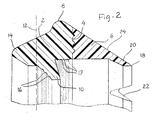
- Fig. 2 is an axial section of the mould and sealing ring shown in Fig. 1.
- Fig. 3 is an axial section of the mould and sealing ring of Fig. 1 and 2 arranged on the surface of a forming mandrel.
- Fig. 4 is an axial section showing the forming of a pipe socket by means of a forming mandrel and the mould and sealing ring according to the invention arranged thereon.
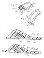
- Fig. 5 is a perspective view of a section of modified embodiment of a mould and sealing ring according to the invention.
- Fig. 6 is a perspective view of a reinforcing portion of a mould and sealing ring according to Fig. 5.
- Fig. 7 is an axial section of the mould and sealing ring of Fig. 5 arranged on a forming mandrel.
- Fig. 8 is an axial section of a further modified embodiment of a mould and sealing ring according to the invention arranged on a forming mandrel.
- The mould and sealing ring according to the invention shown in Figs 1-4 comprises a
sealing portion 2 consisting of rubber and a reinforcingportion 6 consisting of relatively rigid plastic material and firmly connected with thesealing portion 2 at aconnection surface 4 having a zigzag-shaped cross-section. At its outer periphery thesealing portion 2 has aportion 8 projecting radially outside theconnection surface 4. At its inner periphery the sealingportion 2 has aportion 10 positioned radially inside theconnection surface 4. Thus, the sealingportion 2 can be considered to be defined by the projectingportions connection surface 4 and a plane coincident with thebroken line 12 of Fig. 2. When utilizing the sealing function of the mould and sealing ring this sealingportion 2 is subjected to a radial compression. In addition to the sealingportion 2 and the reinforcingportion 6 the mould and sealing ring comprises aportion 14 unitary with the sealingportion 2 and positioned at the opposite side of thebroken line 12 from the sealingportion 2. Even if theportion 14 can contribute to the sealing function of the mould and sealing ring for example by acting as a sealing lip it does not constitute an active sealing portion of the mould and sealing ring according to the invention in the same way as thesealing portion 2. Thus, it is for economic reasons possible to manufacture also theportion 14 from a plastic material which is less costly than the rubber material of the sealingportion 2. The sealingportion 2 is provided withridges - The reinforcing
portion 6 consisting of plastic material is substantially wedge-shaped and forms at its side opposite from the connection surface 4 a relativelysharp side edge 18. Adjacent to theside edge 18 the reinforcingportion 6 forms anedge portion 20 of successively reduced inner diameter. Theedge portion 20 is resiliently expandable to a position in which the inner surface of theedge portion 20 approaches a cylindrical shape, the resiliency being provided by the fact that theedge portion 20 is interrupted by a number of recesses provided along the periphery of theside edge portion 20. Thereby, it is suitable that the sprues formed at the manufacturing of the reinforcingportion 6 consisting of plastic are located to the bottom of therecesses 22 where the sprues do not disturb the forming operation. At itsouter surface 24 the reinforcingportion 6 constitutes a substantially conical surface having a knurled structure. - In Fig. 3 the mould and sealing ring is shown in a tensioned position in a
shallow groove 25 on the substantial cylindricalouter surface 26 of a formingmandrel 28. Thegroove 25 comprises adeeper portion 25a engaged by theportion 10 of the ring and a more shallow portion 25b engaged by the inner surface of the reinforcingportion 6. In the tensioned position on themandrel 28 theportion 10 is compressed and theedge portion 20 of the reinforcing portion is resiliently expanded, the inner surface of the ring positioned between theportion 10 and theedge portion 20 being located at a small radial distance from the bottom of thegroove 25, so that the ring is somewhat resiliently resting on theportion 10 and theedge portion 20. Because of its tendency to return to the position of Fig. 2 theedge portion 20 is at a great force pressed against the outer surface of the formingmandrel 28 so that thesharp side edge 18 closely engages thesurface 26. - When forming a socket at the end portion of a thermoplastic pipe the pipe end portion is pushed over the mould portions constituted by the
mandrel 28 and the mould and sealing ring, as shown in Fig. 4, the reinforcingportion 6 of the mould and sealing ring forming at itsouter surface 24 the substantial forming or moulding surface of the mould and sealing ring. Because of the fact that thesurface 24 is in close connection with thesurface 26 of the mandrel and forms a rigid abutment there is provided for a reliable displacement of thepipe end portion 30 over the mould and sealing ring without any tendency of displacement of the ring on the surface of the mandrel. The knurled structure of thesurface 24 facilitates the sliding of thepipe end portion 30 along the surface in question. - The mould and sealing ring forms an inner groove in the socket end of the
pipe end portion 30 and after the withdrawal of themandrel 26 from the pipe end portion after the cooling of the softened pipe end portion the mould and sealing ring is retained in the groove in a locked-in position provided by the reinforcingportion 26. In this position the portion of the mould and sealing ring which is active from the sealing point of view substantially consists of the sealingportion 2. When providing a pipe joint thesealing portion 2 is compressed between the bottom of the groove formed in the socket and the outer surface of a spigot end of a pipe end portion introduced into the socket, said spigot forming together with the pipe end portion a pipe joint. However, theportion 14 can be designed so as to form a lip seal engaging the outer surface of said spigot end. From the sealing point of view the reinforcingportion 6 is completely inactive. However, the reinforcingportion 6 can contribute to the stability of the joint by striving to take the inwards directed position shown in Fig. 2 and thereby engaging the outer surface of the spigot end at theedge 18. - In Fig. 5 there is shown a mould and sealing ring according to the invention which is slightly modified with regard to the design of the connection surface between the
sealing portion 2a and the reinforcingportion 6a and with regard to the design of the recesses at the side edge portion 20a of the reinforcingportion 6a. Thus, in the embodiment according to Fig. 5a the sealingportion 2a and the reinforcingportion 6a are connected with each other at a connection surface 32a which is of substantially V-shaped cross-section provided that the reinforcingportion 6a extends into the sealingportion 2a between the portions 8a and 10a thereof. This provides a stiffening of the sealingportion 2a between the portions 8a and 10a thereof. In the embodiment of Fig. 5 the recesses in the side edge portion 20a of the reinforcingportion 6a are formed as slots 22a positioned at a small distance from each other. - In order further to improve the binding between the sealing portion and the reinforcing portion the connection surface can be provided with recesses 34a as shown in Fig. 6.
- The mould and sealing ring shown in Fig. 5 differs from the sealing ring according to Figs 1-4 also in the respect that the reinforcing
portion 6a is provided with ashoulder 36, as shown in Fig. 7 utilized for anchoring the mould and sealing ring to the outer surface 26a of themandrel 28a in a more reliable way. In accordance therewith theshoulder 36 engages aprojection 38 of the surface 26a. - In Fig. 8 there is shown an embodiment of the mould and sealing ring according to the invention, in which the reinforcing
portion 6a is provided with ashoulder 40 corresponding to theshoulder 36 in the embodiment of Fig. 7. Theshoulder 40 is positioned within the region of the resilient side edge portion 20a of the reinforcingportion 6a. - The invention can be modified within the scope of the following claims.
Claims (10)
Priority Applications (1)
| Application Number | Priority Date | Filing Date | Title |
|---|---|---|---|
| AT87850108T ATE57329T1 (en) | 1986-04-17 | 1987-04-02 | MOLDING AND SEALING RING. |
Applications Claiming Priority (2)
| Application Number | Priority Date | Filing Date | Title |
|---|---|---|---|
| SE8601750A SE463664B (en) | 1986-04-17 | 1986-04-17 | FORMING AND SEALING RING |
| SE8601750 | 1986-04-17 |
Publications (3)
| Publication Number | Publication Date |
|---|---|
| EP0243331A2 true EP0243331A2 (en) | 1987-10-28 |
| EP0243331A3 EP0243331A3 (en) | 1988-06-08 |
| EP0243331B1 EP0243331B1 (en) | 1990-10-10 |
Family
ID=20364227
Family Applications (1)
| Application Number | Title | Priority Date | Filing Date |
|---|---|---|---|
| EP87850108A Expired - Lifetime EP0243331B1 (en) | 1986-04-17 | 1987-04-02 | A mould and sealing ring |
Country Status (14)
| Country | Link |
|---|---|
| US (1) | US4818209A (en) |
| EP (1) | EP0243331B1 (en) |
| JP (1) | JPS6322626A (en) |
| AT (1) | ATE57329T1 (en) |
| AU (1) | AU585705B2 (en) |
| CA (1) | CA1291185C (en) |
| DE (1) | DE3765450D1 (en) |
| DK (1) | DK164808C (en) |
| ES (1) | ES2018851B3 (en) |
| FI (1) | FI85539C (en) |
| IE (1) | IE60215B1 (en) |
| NO (1) | NO168848C (en) |
| SE (1) | SE463664B (en) |
| ZA (1) | ZA872531B (en) |
Cited By (5)
| Publication number | Priority date | Publication date | Assignee | Title |
|---|---|---|---|---|
| US6969481B2 (en) | 2001-08-02 | 2005-11-29 | Helmuth Schnallinger | Method for producing a pipe termination box from thermoplastic material |
| EP1818589A2 (en) | 2006-02-10 | 2007-08-15 | Semperit Aktiengesellschaft Holding | Sealing ring and sealing device with the sealing ring |
| WO2008067896A1 (en) | 2006-12-05 | 2008-06-12 | Poloplast Gmbh & Co. Kg | Insertable pipe end sleeve comprising a bead |
| AT504096B1 (en) * | 2006-07-17 | 2008-07-15 | Semperit Ag Holding | SEAL RING AND CONNECTING DEVICE FOR A SOCKET CONNECTION |
| FR2939177A1 (en) * | 2008-12-01 | 2010-06-04 | Saint Gobain Pont A Mousson | SEAL ASSEMBLY AND CORRESPONDING TUBULAR JUNCTION |
Families Citing this family (62)
| Publication number | Priority date | Publication date | Assignee | Title |
|---|---|---|---|---|
| USD323024S (en) | 1986-04-17 | 1992-01-07 | Stefan Petersson | Sealing ring |
| SE464283B (en) * | 1986-10-15 | 1991-04-08 | Forsheda Ab | SEAT AND MACHINE FORMING A END PART ON A PIPE |
| USD347885S (en) | 1990-04-18 | 1994-06-14 | Forsheda Ab | Sealing ring for sealing jointed pipes |
| USD326710S (en) | 1990-09-24 | 1992-06-02 | Vassallo Research & Development Corp. | Gasket |
| USD330073S (en) | 1991-08-30 | 1992-10-06 | Vassallo Research & Development Corp. | Gasket |
| US5213339A (en) * | 1992-02-13 | 1993-05-25 | Reeves Rubber, Inc. | Pipe joint gasket |
| SE505267C2 (en) | 1992-03-10 | 1997-07-28 | Forsheda Ab | Methods of preparing at least two different types of sealing rings and sealing elements for use in carrying out the method |
| USD351459S (en) | 1992-09-10 | 1994-10-11 | Forsheda Ab | Sealing ring |
| US5639959A (en) * | 1993-09-24 | 1997-06-17 | Reiber; Harold Steven | Corrosion measurement apparatus and galvanic coupon and gasket therefor |
| USD362902S (en) | 1993-09-24 | 1995-10-03 | Hdr Engineering, Inc. | Gasket |
| EP0686245B1 (en) * | 1993-12-15 | 2000-06-14 | Forsheda AB | A sealing device, a mould element and a pipe |
| USD374710S (en) | 1994-01-25 | 1996-10-15 | Forsheda Ab | Sealing ring |
| US5951022A (en) * | 1997-10-06 | 1999-09-14 | Gorman Company, Inc. | Fluid seal device with reinforced dynamic lip |
| US6152494A (en) * | 1998-01-12 | 2000-11-28 | S&B Technical Products, Inc. | Pipe gasket with combined lip and compression seal geometries |
| US6105972A (en) * | 1998-01-12 | 2000-08-22 | S & B Technical Products, Inc. | Pipe gasket with improved low insertion geometry |
| US6113159A (en) * | 1998-08-21 | 2000-09-05 | S&B Technical Products, Inc. | Pipe gasket with shielded band |
| US5988695A (en) * | 1998-08-26 | 1999-11-23 | S&B Technical Products, Inc. | Pipe gasket with embedded ring |
| US6299176B1 (en) * | 1999-03-03 | 2001-10-09 | S&B Technical Products | Dual purpose low insertion force gasket |
| US6142484A (en) * | 1999-04-15 | 2000-11-07 | Vassallo Research & Development Corporation | Composite multi-pressure gasket |
| US6367802B1 (en) | 1999-11-30 | 2002-04-09 | Malcolm Mann Inc. | Annular gasket with locking structure |
| US6422569B1 (en) | 1999-11-30 | 2002-07-23 | Parker-Hannifin Corporation | Snap-in retainer for a fluid seal |
| WO2001077561A2 (en) * | 2000-04-05 | 2001-10-18 | S & B Technical Products, Inc. | Method of forming a pipe joint between telescoping pipe sections |
| US6499744B1 (en) * | 2000-06-05 | 2002-12-31 | S&B Technical Products, Inc. | Pipe gasket with dual purpose tail |
| US7469905B2 (en) * | 2000-11-30 | 2008-12-30 | Springseal Inc. | Permanently lubricated film gasket and method of manufacture |
| US6550775B2 (en) | 2000-11-30 | 2003-04-22 | Malcolm Mann, Inc. | Annular gasket |
| US20040041347A1 (en) * | 2000-11-30 | 2004-03-04 | Beach Jefferey Kurtis | Permanently lubricated gasket |
| US7140618B2 (en) * | 2003-01-16 | 2006-11-28 | Vassallo Research & Development Corporation | Socket with dual-functional composite gasket |
| US7090225B2 (en) * | 2003-06-03 | 2006-08-15 | Aqua Glass Corporation | Water-proof seal for a towel bar which penetrates a tub surround portion |
| US7134204B2 (en) * | 2003-08-25 | 2006-11-14 | S & B Technical Products, Inc. | Integral restraint system and method of manufacture for plastic pipe |
| US7185894B2 (en) * | 2004-06-09 | 2007-03-06 | Advanced Drainage Systems, Inc. | Watertight corrugated pipe gasket |
| CN100429449C (en) * | 2004-06-17 | 2008-10-29 | 章根友 | Connecting structure of pipes |
| DE502005006789D1 (en) * | 2004-07-20 | 2009-04-23 | Bode Gmbh | Sealing ring for push-in joints |
| US7731884B2 (en) | 2004-12-08 | 2010-06-08 | Advanced Elastomer Systems, L.P. | Molded gasket and method of making |
| US7252293B2 (en) | 2005-02-04 | 2007-08-07 | Press-Seal Gasket Corporation | Two-part gasket for pipe-to-pipe connections |
| DE102005025460A1 (en) * | 2005-06-02 | 2006-12-07 | Poloplast Gmbh & Co.Kg | Method for producing a pipe end sleeve and bead insert for forming a bead of a Rohrendsteckmuffe |
| US8235427B2 (en) * | 2005-06-10 | 2012-08-07 | S & B Technical Products, Inc. | Self restrained ductile iron fitting |
| ITUD20050127A1 (en) * | 2005-07-29 | 2007-01-30 | Daniela Plebani | GASKET FOR A LINK BETWEEN TUBES |
| US7423216B2 (en) * | 2006-01-23 | 2008-09-09 | Watlow Electric Manufacturing Company | Dual action sealing gasket and use thereof in an electrical housing assembly |
| SE0600872L (en) * | 2006-04-21 | 2007-01-09 | Trelleborg Forsheda Building A | LUTE |
| USD556866S1 (en) * | 2006-05-22 | 2007-12-04 | S & B Technical Products, Inc. | Pipe gasket with wiper lip |
| USD559363S1 (en) * | 2006-05-30 | 2008-01-08 | S & B Technical Products, Inc. | Pipe gasket |
| USD557386S1 (en) * | 2006-05-30 | 2007-12-11 | S & B Technical Products, Inc. | Pipe gasket |
| USD557771S1 (en) * | 2006-10-06 | 2007-12-18 | S & B Technical Products, Inc. | Pipe gasket |
| US8474830B2 (en) | 2007-06-07 | 2013-07-02 | Springseal, Inc. | Gasket |
| US20090273184A1 (en) * | 2008-04-30 | 2009-11-05 | Michael Wright | Self restrained joint for ductile iron pipe and fittings |
| WO2009151938A1 (en) | 2008-05-27 | 2009-12-17 | Springseal Inc. | Pipe coupling assembly |
| WO2010080394A2 (en) * | 2008-12-18 | 2010-07-15 | Honeywell International Inc. | Sealing grommet for fluid filters |
| GB0921634D0 (en) * | 2009-12-10 | 2010-01-27 | Artificial Lift Co Ltd | Seal,assembly and method,particularly for downhole electric cable terminations |
| US8801049B2 (en) | 2011-04-29 | 2014-08-12 | Springseal, Inc. | Pipe coupling system and method |
| US9593787B2 (en) | 2013-06-21 | 2017-03-14 | S & B Technical Products, Inc. | Secured in place gasket for sealing plastic pipelines, method of manufacture and method of installation |
| US20140374994A1 (en) | 2013-06-21 | 2014-12-25 | S & B Technical Products, Inc. | Secured in Place Gasket for Sealing Plastic Pipelines, Method of Manufacture and Method of Installation |
| US9951869B2 (en) | 2015-02-04 | 2018-04-24 | Trelleborg Pipe Seals Lelystad BV | Seal for belled pipe |
| US10295060B2 (en) * | 2015-06-25 | 2019-05-21 | Evolution Engineering Inc. | Method for sealing a gap sub assembly |
| US10328631B2 (en) * | 2015-09-30 | 2019-06-25 | Mcwane, Inc. | Apparatus and mandrel-assisted method for forming a plastic pipe socket containing a restrained gasket |
| US10393296B2 (en) * | 2016-09-30 | 2019-08-27 | S & B Technical Products, Inc. | Sealing gasket with corrugated insert for sealing restrained or non-restrained plastic pipelines |
| US10808844B2 (en) * | 2017-02-06 | 2020-10-20 | North American Pipe Corporation | System, method and apparatus for pipe restrained joint seal and lock |
| US10876672B2 (en) * | 2017-02-24 | 2020-12-29 | S & B Technical Products, Inc. | Sealing joint for low pressure pipe systems and method of manufacture |
| US10648602B2 (en) | 2017-05-23 | 2020-05-12 | S&B Technical Products, Inc | Sealing gasket with specialized reinforcing ring for sealing plastic pipelines |
| AU2021382634A1 (en) * | 2020-11-23 | 2023-06-22 | North American Pipe Corporation | Pipe joint insert device, pipe joint assembly, and methods of forming same |
| EP4251892A4 (en) * | 2020-11-24 | 2024-12-04 | S & B Technical Products, Inc. | SEALING JOINT FOR MALLEABLE IRON PIPE AND METHOD OF MANUFACTURE |
| US12085199B2 (en) * | 2020-11-24 | 2024-09-10 | S & B Technical Products, Inc. | Sealing gasket for ductile iron pipe and method of manufacture |
| USD986394S1 (en) * | 2021-05-12 | 2023-05-16 | S & B Technical Products, Inc. | Pipe sealing gasket |
Family Cites Families (18)
| Publication number | Priority date | Publication date | Assignee | Title |
|---|---|---|---|---|
| US2585453A (en) * | 1949-04-08 | 1952-02-12 | John P Gallagher | Interchangeable, self-releasing, self-locking high-pressure tube and pipe connector unit |
| US3078332A (en) * | 1959-10-02 | 1963-02-19 | Dresser Ind | Electro-conductive pipe coupling |
| US3455566A (en) * | 1966-03-11 | 1969-07-15 | John W Hull | Fluid sealing arrangements |
| US3469854A (en) * | 1966-11-04 | 1969-09-30 | Hall & Hall Ltd | Header ring |
| US3716245A (en) * | 1969-03-10 | 1973-02-13 | M Turolla | Ring seal |
| US3813107A (en) * | 1971-03-24 | 1974-05-28 | Lok Corp A | Gasket seal between sewer pipe and manhole opening |
| US3856315A (en) * | 1973-01-02 | 1974-12-24 | P Stansbury | Bell and spigot pvc pipe joint |
| US4120521A (en) * | 1975-08-28 | 1978-10-17 | Rieber & Son Plastic-Industri A/S | Combined mould element and sealing ring |
| US4188040A (en) * | 1977-04-06 | 1980-02-12 | Firma WOCO Franz-Josef Wolf & Co. | Sealing ring |
| JPS5814311Y2 (en) * | 1977-11-22 | 1983-03-22 | 株式会社クボタ | Pipe joint structure |
| US4182519A (en) * | 1978-01-24 | 1980-01-08 | Ralph Wilson | Resilient sealing ring |
| US4223896A (en) * | 1979-03-13 | 1980-09-23 | Ab Gustavsberg | Sealing ring |
| GB2043802B (en) * | 1979-03-14 | 1983-03-09 | Gustavsberg Ab | Seals |
| IT1123216B (en) * | 1979-09-19 | 1986-04-30 | Alberto Rovetta | MULTISCOPE MECHANICAL HAND |
| JPS56126118A (en) * | 1980-03-10 | 1981-10-02 | Kubota Ltd | Working method of plastic pipe socket |
| US4336014A (en) * | 1980-09-15 | 1982-06-22 | Rieber & Son A/S | System for mounting a forming element on a mandrel |
| US4637618A (en) * | 1984-07-13 | 1987-01-20 | Vassallo Research & Development Corporation | Composite gasket and fitting including same |
| US4625383A (en) * | 1985-03-18 | 1986-12-02 | Vassallo Research And Development Corporation | Method for seating a gasket in a plastic pipe bell using a hard configured ring |
-
1986
- 1986-04-17 SE SE8601750A patent/SE463664B/en not_active IP Right Cessation
-
1987
- 1987-04-02 AT AT87850108T patent/ATE57329T1/en not_active IP Right Cessation
- 1987-04-02 DE DE8787850108T patent/DE3765450D1/en not_active Expired - Lifetime
- 1987-04-02 ES ES87850108T patent/ES2018851B3/en not_active Expired - Lifetime
- 1987-04-02 EP EP87850108A patent/EP0243331B1/en not_active Expired - Lifetime
- 1987-04-07 FI FI871525A patent/FI85539C/en not_active IP Right Cessation
- 1987-04-08 ZA ZA872531A patent/ZA872531B/en unknown
- 1987-04-10 NO NO871503A patent/NO168848C/en unknown
- 1987-04-15 DK DK197187A patent/DK164808C/en not_active IP Right Cessation
- 1987-04-15 US US07/038,737 patent/US4818209A/en not_active Expired - Lifetime
- 1987-04-16 CA CA000535017A patent/CA1291185C/en not_active Expired - Fee Related
- 1987-04-16 IE IE100287A patent/IE60215B1/en not_active IP Right Cessation
- 1987-04-16 AU AU71586/87A patent/AU585705B2/en not_active Expired
- 1987-04-16 JP JP62094272A patent/JPS6322626A/en active Granted
Cited By (7)
| Publication number | Priority date | Publication date | Assignee | Title |
|---|---|---|---|---|
| US6969481B2 (en) | 2001-08-02 | 2005-11-29 | Helmuth Schnallinger | Method for producing a pipe termination box from thermoplastic material |
| EP1818589A2 (en) | 2006-02-10 | 2007-08-15 | Semperit Aktiengesellschaft Holding | Sealing ring and sealing device with the sealing ring |
| EP1818589A3 (en) * | 2006-02-10 | 2011-04-13 | Semperit Aktiengesellschaft Holding | Sealing ring and sealing device with the sealing ring |
| AT504096B1 (en) * | 2006-07-17 | 2008-07-15 | Semperit Ag Holding | SEAL RING AND CONNECTING DEVICE FOR A SOCKET CONNECTION |
| WO2008067896A1 (en) | 2006-12-05 | 2008-06-12 | Poloplast Gmbh & Co. Kg | Insertable pipe end sleeve comprising a bead |
| FR2939177A1 (en) * | 2008-12-01 | 2010-06-04 | Saint Gobain Pont A Mousson | SEAL ASSEMBLY AND CORRESPONDING TUBULAR JUNCTION |
| WO2010063931A3 (en) * | 2008-12-01 | 2010-07-29 | Saint-Gobain Pam | Seal assembly and corresponding tubular joint |
Also Published As
| Publication number | Publication date |
|---|---|
| JPH0364293B2 (en) | 1991-10-04 |
| EP0243331B1 (en) | 1990-10-10 |
| IE60215B1 (en) | 1994-06-15 |
| SE8601750L (en) | 1987-10-18 |
| JPS6322626A (en) | 1988-01-30 |
| DK164808C (en) | 1993-01-04 |
| ZA872531B (en) | 1987-11-25 |
| CA1291185C (en) | 1991-10-22 |
| ATE57329T1 (en) | 1990-10-15 |
| FI85539C (en) | 1992-04-27 |
| SE8601750D0 (en) | 1986-04-17 |
| DK197187A (en) | 1987-10-18 |
| ES2018851B3 (en) | 1991-05-16 |
| NO871503L (en) | 1987-10-19 |
| US4818209A (en) | 1989-04-04 |
| FI85539B (en) | 1992-01-15 |
| NO168848C (en) | 1992-04-08 |
| SE463664B (en) | 1991-01-07 |
| FI871525A7 (en) | 1987-10-18 |
| DK164808B (en) | 1992-08-24 |
| FI871525A0 (en) | 1987-04-07 |
| DK197187D0 (en) | 1987-04-15 |
| IE871002L (en) | 1987-10-17 |
| DE3765450D1 (en) | 1990-11-15 |
| NO168848B (en) | 1991-12-30 |
| NO871503D0 (en) | 1987-04-10 |
| EP0243331A3 (en) | 1988-06-08 |
| AU7158687A (en) | 1987-10-22 |
| AU585705B2 (en) | 1989-06-22 |
Similar Documents
| Publication | Publication Date | Title |
|---|---|---|
| EP0243331B1 (en) | A mould and sealing ring | |
| US4441745A (en) | Coupling pipe part for interconnecting corrugated pipe parts | |
| US5064207A (en) | Sealing ring for sealing a pipe joint | |
| US5094482A (en) | Corrugated plastic pipe connector | |
| US4923227A (en) | Corrugated plastic pipe connector | |
| US4458904A (en) | Seal for use with pipes to be fitted one into another with spigot and socket ends | |
| US6199915B1 (en) | Connector element for tubing or hoses | |
| US4304415A (en) | Packing ring for ribbed conduits | |
| US4368894A (en) | Reinforced sealing rings for pipe joints | |
| US4934716A (en) | Pipe sealing ring and method of manufacturing the same | |
| EP0560104B1 (en) | Method for manufacturing sealing rings | |
| GB2161568A (en) | Hose coupling | |
| US4547005A (en) | Connecting pipe part of a resilient material | |
| CN1440498A (en) | Connecting accessories with locking clamping projections for circumferentially ribbed elongated bodies | |
| WO1980001307A1 (en) | Shaft seal with retractable polytetrafluoroethylene-lined sealing lip | |
| US4223896A (en) | Sealing ring | |
| US4103498A (en) | Plugs for bores in rocks or the like | |
| GB2173851A (en) | Flex-action rivet for securing sheets together | |
| EP1197162B1 (en) | Cosmetic container | |
| US5775830A (en) | Watertight connector casing | |
| US4660839A (en) | Endless backup ring for hydraulic apparatus seal | |
| JPH062791A (en) | Detachment prevention fitting | |
| JPH0379813A (en) | High speed coupling | |
| US20020084598A1 (en) | Valve member with a crimped gasket, and a method of manufacturing such a member | |
| US20070071546A1 (en) | Boot |
Legal Events
| Date | Code | Title | Description |
|---|---|---|---|
| PUAI | Public reference made under article 153(3) epc to a published international application that has entered the european phase |
Free format text: ORIGINAL CODE: 0009012 |
|
| AK | Designated contracting states |
Kind code of ref document: A2 Designated state(s): AT BE CH DE ES FR GB IT LI NL SE |
|
| PUAL | Search report despatched |
Free format text: ORIGINAL CODE: 0009013 |
|
| AK | Designated contracting states |
Kind code of ref document: A3 Designated state(s): AT BE CH DE ES FR GB IT LI NL SE |
|
| 17P | Request for examination filed |
Effective date: 19881207 |
|
| 17Q | First examination report despatched |
Effective date: 19891106 |
|
| ITF | It: translation for a ep patent filed | ||
| GRAA | (expected) grant |
Free format text: ORIGINAL CODE: 0009210 |
|
| AK | Designated contracting states |
Kind code of ref document: B1 Designated state(s): AT BE CH DE ES FR GB IT LI NL SE |
|
| PG25 | Lapsed in a contracting state [announced via postgrant information from national office to epo] |
Ref country code: SE Effective date: 19901010 |
|
| REF | Corresponds to: |
Ref document number: 57329 Country of ref document: AT Date of ref document: 19901015 Kind code of ref document: T |
|
| ET | Fr: translation filed | ||
| REF | Corresponds to: |
Ref document number: 3765450 Country of ref document: DE Date of ref document: 19901115 |
|
| ITTA | It: last paid annual fee | ||
| PLBE | No opposition filed within time limit |
Free format text: ORIGINAL CODE: 0009261 |
|
| STAA | Information on the status of an ep patent application or granted ep patent |
Free format text: STATUS: NO OPPOSITION FILED WITHIN TIME LIMIT |
|
| 26N | No opposition filed | ||
| REG | Reference to a national code |
Ref country code: GB Ref legal event code: IF02 |
|
| PGFP | Annual fee paid to national office [announced via postgrant information from national office to epo] |
Ref country code: CH Payment date: 20050405 Year of fee payment: 19 |
|
| PGFP | Annual fee paid to national office [announced via postgrant information from national office to epo] |
Ref country code: AT Payment date: 20050406 Year of fee payment: 19 |
|
| PGFP | Annual fee paid to national office [announced via postgrant information from national office to epo] |
Ref country code: ES Payment date: 20050419 Year of fee payment: 19 |
|
| PG25 | Lapsed in a contracting state [announced via postgrant information from national office to epo] |
Ref country code: AT Free format text: LAPSE BECAUSE OF NON-PAYMENT OF DUE FEES Effective date: 20060402 |
|
| PG25 | Lapsed in a contracting state [announced via postgrant information from national office to epo] |
Ref country code: ES Free format text: LAPSE BECAUSE OF NON-PAYMENT OF DUE FEES Effective date: 20060403 |
|
| PGFP | Annual fee paid to national office [announced via postgrant information from national office to epo] |
Ref country code: NL Payment date: 20060405 Year of fee payment: 20 Ref country code: DE Payment date: 20060405 Year of fee payment: 20 Ref country code: BE Payment date: 20060405 Year of fee payment: 20 |
|
| PGFP | Annual fee paid to national office [announced via postgrant information from national office to epo] |
Ref country code: GB Payment date: 20060406 Year of fee payment: 20 |
|
| PGFP | Annual fee paid to national office [announced via postgrant information from national office to epo] |
Ref country code: FR Payment date: 20060412 Year of fee payment: 20 |
|
| PG25 | Lapsed in a contracting state [announced via postgrant information from national office to epo] |
Ref country code: LI Free format text: LAPSE BECAUSE OF NON-PAYMENT OF DUE FEES Effective date: 20060430 Ref country code: CH Free format text: LAPSE BECAUSE OF NON-PAYMENT OF DUE FEES Effective date: 20060430 |
|
| PGFP | Annual fee paid to national office [announced via postgrant information from national office to epo] |
Ref country code: IT Payment date: 20060430 Year of fee payment: 20 |
|
| REG | Reference to a national code |
Ref country code: CH Ref legal event code: PL |
|
| PG25 | Lapsed in a contracting state [announced via postgrant information from national office to epo] |
Ref country code: GB Free format text: LAPSE BECAUSE OF EXPIRATION OF PROTECTION Effective date: 20070401 |
|
| PG25 | Lapsed in a contracting state [announced via postgrant information from national office to epo] |
Ref country code: NL Free format text: LAPSE BECAUSE OF EXPIRATION OF PROTECTION Effective date: 20070402 |
|
| REG | Reference to a national code |
Ref country code: GB Ref legal event code: PE20 |
|
| NLV7 | Nl: ceased due to reaching the maximum lifetime of a patent |
Effective date: 20070402 |
|
| REG | Reference to a national code |
Ref country code: ES Ref legal event code: FD2A Effective date: 20060403 |
|
| BE20 | Be: patent expired |
Owner name: *FORSHEDA A.B. Effective date: 20070402 |