EP0243094A2 - Procédé pour la fabrication d'un moule - Google Patents
Procédé pour la fabrication d'un moule Download PDFInfo
- Publication number
- EP0243094A2 EP0243094A2 EP87303352A EP87303352A EP0243094A2 EP 0243094 A2 EP0243094 A2 EP 0243094A2 EP 87303352 A EP87303352 A EP 87303352A EP 87303352 A EP87303352 A EP 87303352A EP 0243094 A2 EP0243094 A2 EP 0243094A2
- Authority
- EP
- European Patent Office
- Prior art keywords
- pattern
- layer
- mold
- ceramic mold
- expansion
- Prior art date
- Legal status (The legal status is an assumption and is not a legal conclusion. Google has not performed a legal analysis and makes no representation as to the accuracy of the status listed.)
- Withdrawn
Links
Images


Classifications
-
- B—PERFORMING OPERATIONS; TRANSPORTING
- B22—CASTING; POWDER METALLURGY
- B22C—FOUNDRY MOULDING
- B22C9/00—Moulds or cores; Moulding processes
- B22C9/02—Sand moulds or like moulds for shaped castings
- B22C9/04—Use of lost patterns
- B22C9/043—Removing the consumable pattern
Definitions
- the present invention relates to a new and improved method of making a mold and more specifically to a method in which a section of ceramic mold material is separated from another section of ceramic mold material.
- a layer of ceramic mold material may be necessary to separate one section of a layer of ceramic mold material from another section of the layer of ceramic mold material.
- a pour cup is made, a generally conical pattern is covered with a layer of ceramic mold material. It is necessary to separate the portion of the layer of ceramic mold material overlying the circular base of the conical pattern from the remainder of the layer of ceramic mold material in order to open the pour cup. This has previously been done by a time consuming abrading or cutting operation.
- a mold assembly having a plurality of separate sections is disclosed in United States Patent No. 4,066,116.
- a wax pattern is repetitively dipped in a slurry of ceramic mold material.
- the resulting wet layer of ceramic mold material is separated into sections by wiping away a portion of the layer of ceramic mold material. After the ceramic mold material has dried, the mold sections can be separated at the location where a discontinuity was formed during the step of wiping away the wet ceramic mold material.
- the present invention provides a new and improved method of making a ceramic mold by covering a pattern member and a body of expansion material with a layer of ceramic mold material.
- the body of expansion material has a greater coefficient of expansion than the layer of ceramic mold material. Therefore, when the body of expansion material and the layer of ceramic mold material are heated, thermal expansion forces are applied against the layer of ceramic mold material by the body of expansion material to crack the layer of ceramic mold material. The cracking of the layer of ceramic mold material results in one section of the layer of ceramic mold material being disconnected from an adjoining section of the layer of ceramic mold material.
- patterns having configurations corresponding to the configurations of the two parts of the mold are provided.
- the patterns are aligned with one another and have interposed therebetween one or more bodies of expansion material.
- the resulting pattern assembly is covered with a layer of ceramic mold material.
- the layer of ceramic mold material extends between and overlies the patterns and the expansion material between the patterns.
- the expansion material has a greater coefficient of thermal expansion than the ceramic mold material.
- the bodies of expansion material are of the appropriate size and shape to crack the desired locations of the ceramic mold material while leaving the other portions of the ceramic mold material undisturbed. Therefore, when the expansion material is heated, it cracks the layer of ceramic mold material to separate the portion of the layer of ceramic mold material overlying one pattern from the ceramic mold material overlying the other pattern.
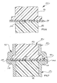
- a pattern assembly 20 for use in forming a mold or a part of a mold includes a first or upper pattern section 22 and a second or lower pattern section 24.
- a body 26 of expansion material is disposed between the upper and lower patterns 22 and 24.
- a wet coating or layer 28 of ceramic mold material is disposed over the pattern assembly 20. The layer 28 of ceramic mold material overlies the upper and lower patterns 22 and 24 and the body 26 of expansion material.
- the patterns are formed of either a natural or artificial wax which is melted upon being heated to a temperature above its melting point, for example to 150 degrees F.
- the liquid wax from the lower pattern section 24 is conducted from inside the layer of ceramic mold material 28 through a suitable opening.
- the molten material of the upper pattern section 22 flows through an opening 32 formed in the body 26 of expansion material and out of the opening in the lower portion of the layer of ceramic mold material.
- the portion of the layer of ceramic mold material overlying the upper pattern 22 is disconnected from the portion of the layer of ceramic mold material overlying the lower pattern 24. This is accomplished by thermally expanding the body 26 of expansion material to crack the layer 28 of ceramic mold material in the manner indicated schematically at 36 in Fig. 2.
- the body 26 of expansion material has a coefficient of thermal expansion which is greater than the coefficient of thermal expansion of the layer 28 of ceramic mold material. Therefore, upon heating of the body 26 of expansion material, it expands to a greater extent than the layer 28 of ceramic mold material. This results in the application of thermal expansion forces against the inside of the layer 28 of ceramic mold material. These thermal expansion forces cause cracks 36 to form in the layer 28 of ceramic mold material.
- the melting temperature of the body 26 of expansion material is substantially greater than the melting temperature of the patterns 22 and 24. Therefore, the expansion material 26 remains intact during melting of the patterns 22 and 24.
- the cracks 36 disconnect the portion of the layer 28 of ceramic mold material overlying the upper pattern section 22 from the portion of the layer of ceramic mold material overlaying the lower pattern section 24. This results in the formation of an upper mold section 40 having a configuration corresponding to the configuration of the upper pattern 22 and a lower mold section 42 having a configuration corresponding to the configuration of the lower pattern 24.
- the upper and lower mold sections 40 and 42 can be easily separated at the cracks 36. Once the upper and lower mold sections 40 and 42 have been separated, the body 26 of expansion material is removed.
- the relatively rough surfaces of the mold sections formed by the cracks 36 may be ground or abraded to have a desired smoothness.
- the body 26 of expansion material may be formed of any desired substance having a greater coefficient of thermal expansion than the coefficient of thermal expansion of the ceramic mold material 28.
- the body 26 of the expansion material was formed of a polymeric material which is commercially available under the trademark "Teflon".
- the coefficient of thermal expansion of "Teflon" that is, the change in length per unit length per degree change in temperature, is approximately 110 per degree centrigrade.
- the sublimation temperature of "Teflon” is approximately 1500 to 1700 degrees F.
- the layer 28 of ceramic mold material was applied over the pattern assembly 20 by repetitively dipping the pattern assembly in a liquid slurry of ceramic mold material.
- the slurry of ceramic mold material contained fused silica, zircon, and other refractory materials in combination with binders. Chemical binders such as ethyl silicate, sodium silicate and colloidal silica can be utilized.
- the slurry may contain suitable film formers such a alginates to control viscosity and wetting agents to control flow characteristics and pattern wettability.
- the layer 28 of ceramic mold material has a coefficient of thermal expansion of approximately 10 per degree centigrade.
- the body 26 of expansion material has been illustrated in Fig. 1 in association with a pair of patterns 22 and 24, the body of expansion material could be used in association with a single pattern member.
- the body 26 of expansion material has been shown as being a sheet.
- the body 26 of expansion material could have a different configuration if desired.
- it is preferred to make the body 26 of "Teflon" other materials could be used if desired.
- the body 26 of expansion material must have a coefficient of thermal expansion which is greater than the coefficient of thermal expansion of the layer 28 of ceramic mold material.
- the present invention can advantageously be used in the formation of a mold assembly 50 (Fig. 3).
- the mold assembly 50 includes a ceramic upper mold section 52 (Fig. 5) which is separable from and fittingly engages a ceramic lower mold section 54 (Fig. 4).
- the upper mold section 52 includes a primary molten metal distribution system 56 which conducts molten metal to the lower mold section 54 through a plurality of joints 60 (Fig. 3) between the upper and lower mold sections.
- the upper mold section 52 (Fig. 5) includes a circular ceramic baffle plate 64.
- the baffle plate 64 is connected with a pour cup 68 in the primary molten metal distribution system 56 by a ceramic post 69.
- the primary molten metal distribution system 56 includes a plurality of hollow runners or arms 70 which extend radially outwardly from the pour cup 68 to the joints 60 (Fig. 3).
- the lower mold section 54 includes a hollow annular secondary molten metal distribution system 74 (Fig. 4) which is connected in fluid communication with the primary molten metal distribution system 56 through the joints 60.
- the ceramic secondary molten metal distribution system 74 is also connected in fluid communication with a plurality of ceramic article molds 76 which extend between the secondary molten metal distribution system 74 and an annular base plate 78.
- the ceramic base plate 78 has a circular opening 80 which receives the baffle plate 64 when the upper and lower mold sections 52 and 54 are interconnected at the separable joints 60.
- the mold When a plurality of articles are to be cast with the mold 50, the mold is raised into a furnace and the upper mold section 52 is connected with an upper end wall of the furnace. Molten metal is then poured into the pour cup 68. The molten metal flows from the pour cup 68 through the primary distribution system 56 and joints 60 to the secondary distribution system 74. The molten metal then flows from the secondary distribution system 74 to the article molds of 76.
- the lower mold section 54 is gradually lowered from the furnace. As this occurs, the upper and lower mold sections 52 and 54 separate at the joints 60 and the article molds 76 move downwardly past the stationary baffle plate 64.
- the manner in which the mold assembly 50 is used to cast a plurality of articles is more fully explained in the aforementioned International Application Serial No. PCT/US86/00166 and will not be further described herein to avoid prolixity of description.
- a wax upper pattern 86 (Fig. 6) having a configuration corresponding to the configuration of the upper mold section 52 is formed.
- the patterns 86 and 88 are constructed by injection molding wax components and interconnecting these components to form each of the patterns.
- the upper and lower patterns 86 and 88 are disposed adjacent to each other at four spaced apart locations corresponding to the four joints 60 where the runners 70 of the primary metal distribution system 56 are connected in fluid communication with the annular passage of the secondary metal distribution system 74.
- a body 92 of expansion material is positioned between the upper and lower pattern sections 86 and 88 at each of the four locations.
- the passages in the arms or runners 70 of the primary distribution system 56 have a rectangular cross-sectional configuration. Therefore, the patterns 86 and 88 have rectangular cross-sectional configurations at the locations where the openings for the joints 60 are to be formed.
- the body 92 of expansion material also has a rectangular configuration. However, the body 92 of expansion material is large enough to project outwardly from the upper and lower patterns 86 and 88.
- the body 92 of expansion material is made of "Teflon".
- the upper and lower patterns 86 and 88 are interconnected with the bodies 92 of expansion material between the pattern to form a pattern assembly 94.
- the entire pattern assembly 94 is covered with a coating or layer 96 of ceramic mold material by repetitively dipping the pattern assembly in a slurry of ceramic mold material.
- the pattern assembly 94 is dipped until a wet layer 96 of ceramic mold material having a thickness of approximately 0.4 inches is built up over the pattern assembly.
- the pattern assembly 94 is then heated to dry the wet layer 96 of ceramic mold material and melt the upper and lower patterns 86 and 88. As the patterns 86 and 88 are melted, the wax in the lower pattern 88 flows out of the dried layer 96 of ceramic mold material through a suitable opening. The wax from part of the pattern flows by gravity from the upper mold part to the lower mold part through an opening 100 formed in the body 92 of expansion material. This wax then flows from the opening in the layer 96 of ceramic mold material.
- the four bodies 92 of expansion material have a larger coefficient of thermal expansion than the layer 96 of ceramic mold material. Therefore, as the bodies 92 of expansion material are heated during the dewaxing of the layer 96 of ceramic mold material, the bodies of the expansion material expand to a greater extent than the ceramic mold material. This results in the generation of thermal expansion forces of a magnitude sufficient to crack the layer 96 of mold material in the manner indicated schematically at 104 in Fig. 7.
- the crack 104 disconnects the portion of the layer 96 of ceramic mold material corresponding to the upper section 52 of the mold from the portion of the layer 96 of ceramic mold material corresponding to the lower section 54 of the mold.
- a crack corresponding to the crack 104 is formed at each of the four locations corresponding to the joints 60. This enables the upper and lower mold sections 52 and 54 to be separated at the cracks 104.
- the lower mold section 54 is moved downwardly away from the upper mold section 52 and withdrawn from a furnace. This requires that the baffle plate 64, connected with the upper mold section 52, be separated from the base plate 78 of the lower mold section 54. In addition, the baffle plate 64 must be small enough to pass through the open central portion of the lower mold section 54.
- the circular baffle plate 64 and annular base plate 78 are formed on a single circular metal pattern member or plate 116 (Fig. 9) having an outside diameter which is approximately the same as the outside diameter of the annular base plate 78.
- a circular ring 120 of expansion material is mounted on the pattern plate 116 in a coaxial relationship with the pattern plate.
- the circular ring 120 is formed of "Teflon" and has an inside diameter which is approximately the same as the outside diameter of the circular baffle plate 64.
- the circular ring 120 has an outside diameter which is approximately the same as the inside diamter of the circular opening 80 in the base plate 78.
- the lower pattern 88 (Fig. 6) is mounted on the pattern plate 116 (Fig. 9) with the open central portion of the pattern aligned with the ring 120 of expansion material.
- the lower pattern 88 engages the plate 116 at locations radially outwardly of the ring 120 of expansion material at locations corresponding to the bottoms of the article molds 76.
- the bodies 92 (Fig. 6) of expansion material are then positioned on the lower pattern 88.
- the upper pattern 86 is then positioned in engagement with the bodies 92 of expansion material.
- a bolt (not shown) extends from the pattern plate 116 to a pattern member in the pour cup of the upper pattern 86 to interconnect the upper and lower patterns 86 and 88. This results in the formation of the pattern assembly 94.
- the entire pattern assembly 94 is repetitively dipped in liquid ceramic mold material in the manner previously explained in connection with Figs. 6 and 7. Therefore the wet coating or layer 96 of ceramic mold material will cover the pattern plate 116 and the ring 120 of expansion material (Fig. 10).
- the radially outer peripheral surface of the circular plate 116 is wiped each time the pattern assembly is dipped to separate the portion of the layer 96 of ceramic mold material overlying the bottom of the plate from the portion of the ceramic mold material overlying the top of the plate.
- the ring 120 of expansion material has a greater coefficient of thermal expansion than the layer 96 of ceramic mold material. Therefore, when the pattern assembly is heated to dry and dewax the layer 96 of ceramic mold material, the ring 120 expands to a greater extent than the layer of ceramic mold material. This results in a cracking of the layer 96 of ceramic mold material adjacent to the ring 120. These cracks disconnect the portion of the layer 96 of ceramic mold material within the ring 120 from the portion of the layer of ceramic mold material outside of the ring. This results in formation of the baffle plate 64 and annular base plate 78.
- ring 120 of expansion material has been described herein as being circular, it is contemplated that the ring could have a different configuration if it is desired to have a baffle plate 64 with a different configuration.
- the ring 120 is, in the illustrated embodiment of the invention, formed of "Teflon". However other materials could be used if desired.
- One of the important features of the invention is the ability to crack the ceramic mold 50 precisely where the parts are to separate and not have it crack in such a manner as to destroy the mold. This is promoted by strategically extending the expansion material into the portions of the mold which are to be cracked. These extensions may be described as a crack producing projections or fingers which will crack the surrounding ceramic material. Another factor is the thickness of the expansion material. A greater cracking force is generated by a thick layer of expansion material than a thin layer.
- the present invention provides a new and improved method of making a ceramic mold by covering a pattern section 22 and a body 26 of expansion material with a layer 28 of ceramic mold material.
- the body 26 of expansion material has a greater coefficient of expansion than the layer 28 of ceramic mold material. Therefore, when the body 26 of expansion material and the layer 28 of ceramic mold material are heated, thermal expansion forces are applied against the layer of ceramic mold material by the body of expansion material to crack the layer of ceramic mold material (Fig. 2).
- the cracking of the layer 28 of ceramic mold material results in one section 40 of the layer of ceramic mold material being disconnected from an adjoining section 42 of the layer of ceramic mold material.
- patterns 86 and 88 having configurations corresponding to the configurations of the two parts 52 and 54 of the mold 50 are provided.
- the patterns 86 and 88 are interconnected with one or more bodies of expansion material 92 between the patterns.
- the resulting pattern assembly 94 is covered with a layer 96 of ceramic mold material.
- the layer 96 of ceramic mold material extends between and overlies and patterns 86 and 88 and the expansion material 92 between the patterns.
- a portion 52 of the layer 96 of ceramic mold material overlying one of the patterns 86 is separated from a portion 54 of the layer of ceramic mold material overlying the other pattern 88 by heating the expansion material 92 and the layer of ceramic mold material.
- the expansion material 92 has a greater coefficient of thermal expansion than the ceramic mold material 96. Therefore, when the expansion material 92 is heated, it cracks the layer of ceramic mold material 96 to separate the portion of the layer of ceramic mold material overlying one pattern 86 from the ceramic mold material overlying the other pattern 88.
Landscapes
- Engineering & Computer Science (AREA)
- Mechanical Engineering (AREA)
- Moulds For Moulding Plastics Or The Like (AREA)
- Devices For Post-Treatments, Processing, Supply, Discharge, And Other Processes (AREA)
Applications Claiming Priority (2)
| Application Number | Priority Date | Filing Date | Title |
|---|---|---|---|
| US06/854,338 US4730657A (en) | 1986-04-21 | 1986-04-21 | Method of making a mold |
| US854338 | 1986-04-21 |
Publications (2)
| Publication Number | Publication Date |
|---|---|
| EP0243094A2 true EP0243094A2 (fr) | 1987-10-28 |
| EP0243094A3 EP0243094A3 (fr) | 1988-02-03 |
Family
ID=25318414
Family Applications (1)
| Application Number | Title | Priority Date | Filing Date |
|---|---|---|---|
| EP87303352A Withdrawn EP0243094A3 (fr) | 1986-04-21 | 1987-04-15 | Procédé pour la fabrication d'un moule |
Country Status (4)
| Country | Link |
|---|---|
| US (1) | US4730657A (fr) |
| EP (1) | EP0243094A3 (fr) |
| JP (1) | JPS635903A (fr) |
| AU (1) | AU7180187A (fr) |
Cited By (1)
| Publication number | Priority date | Publication date | Assignee | Title |
|---|---|---|---|---|
| EP1604753A1 (fr) * | 2004-05-06 | 2005-12-14 | United Technologies Corporation | Coulée de précision |
Families Citing this family (9)
| Publication number | Priority date | Publication date | Assignee | Title |
|---|---|---|---|---|
| US5735336A (en) * | 1995-08-11 | 1998-04-07 | Johnson & Johnson Professional, Inc. | Investment casting method utilizing polymeric casting patterns |
| US5762125A (en) * | 1996-09-30 | 1998-06-09 | Johnson & Johnson Professional, Inc. | Custom bioimplantable article |
| US5782289A (en) * | 1996-09-30 | 1998-07-21 | Johnson & Johnson Professional, Inc. | Investment casting |
| US5906234A (en) * | 1996-10-22 | 1999-05-25 | Johnson & Johnson Professional, Inc. | Investment casting |
| US6663347B2 (en) * | 2001-06-06 | 2003-12-16 | Borgwarner, Inc. | Cast titanium compressor wheel |
| US8931544B2 (en) | 2013-03-15 | 2015-01-13 | Metal Casting Technology, Inc. | Refractory mold |
| US8936066B2 (en) | 2013-03-15 | 2015-01-20 | Metal Casting Technology, Inc. | Method of using a refractory mold |
| US8931542B2 (en) | 2013-03-15 | 2015-01-13 | Metal Casting Technology, Inc. | Method of making a refractory mold |
| KR102276164B1 (ko) * | 2019-05-27 | 2021-07-12 | 주식회사 디이엘 | 콘크리트 표면에 문양을 형성하는 방법 |
Family Cites Families (5)
| Publication number | Priority date | Publication date | Assignee | Title |
|---|---|---|---|---|
| US4066116A (en) * | 1976-01-29 | 1978-01-03 | Trw Inc. | Mold assembly and method of making the same |
| US4196769A (en) * | 1978-03-20 | 1980-04-08 | Remet Corporation | Ceramic shell mold |
| US4276922A (en) * | 1978-05-24 | 1981-07-07 | Trw Inc. | Plug mold assembly |
| US4651799A (en) * | 1986-01-30 | 1987-03-24 | Hitchiner Manufacturing Co., Inc. | Vented casting molds and process of making the same |
| US4667728A (en) * | 1986-04-21 | 1987-05-26 | Pcc Airfoils, Inc. | Method and apparatus for casting articles |
-
1986
- 1986-04-21 US US06/854,338 patent/US4730657A/en not_active Expired - Fee Related
-
1987
- 1987-04-15 EP EP87303352A patent/EP0243094A3/fr not_active Withdrawn
- 1987-04-21 JP JP62098464A patent/JPS635903A/ja active Pending
- 1987-04-21 AU AU71801/87A patent/AU7180187A/en not_active Abandoned
Cited By (1)
| Publication number | Priority date | Publication date | Assignee | Title |
|---|---|---|---|---|
| EP1604753A1 (fr) * | 2004-05-06 | 2005-12-14 | United Technologies Corporation | Coulée de précision |
Also Published As
| Publication number | Publication date |
|---|---|
| JPS635903A (ja) | 1988-01-11 |
| AU7180187A (en) | 1987-10-22 |
| US4730657A (en) | 1988-03-15 |
| EP0243094A3 (fr) | 1988-02-03 |
Similar Documents
| Publication | Publication Date | Title |
|---|---|---|
| US4728258A (en) | Turbine engine component and method of making the same | |
| US4730657A (en) | Method of making a mold | |
| US5069265A (en) | Method of making a turbine engine component | |
| CA1083775A (fr) | Methode de fabrication d'un moule | |
| CA1039925A (fr) | Moule multicouches monolithique | |
| US4724891A (en) | Thin wall casting | |
| US4195683A (en) | Method of forming metal article having plurality of airfoils extending outwardly from a hub | |
| US4955423A (en) | Method of making a turbine engine component | |
| US6364001B1 (en) | Method of casting an article | |
| US5181550A (en) | Method of making a turbine engine component | |
| US6129138A (en) | Method of making a ceramic shell mould and a method of casting | |
| JPS6243777B2 (fr) | ||
| EP1753561B1 (fr) | Ameliorations apportees au moulage a la cire perdue | |
| EP0104794B1 (fr) | Procédé de coulée d'une roue d'une seule pièce | |
| US4667728A (en) | Method and apparatus for casting articles | |
| EP0218735B1 (fr) | Moulage à la cire perdue utilisant une carotte métallique | |
| US4340107A (en) | Ceramic shell molding apparatus and methods | |
| CA1109633A (fr) | Moule et methode de preparation connexe | |
| US3339622A (en) | Method of removing patterns from investment molds | |
| JP2503673B2 (ja) | 精密鋳造用鋳型の製造方法 | |
| US3041688A (en) | Shell mold for investment castings and method of making same | |
| GB2078596A (en) | Method of Making a Blade | |
| US2845667A (en) | Molds for casting disc-shaped bodies | |
| WO1979000795A1 (fr) | Membre formant ouverture pour modeles gazeifiables | |
| GB2260284A (en) | A mould for casting components |
Legal Events
| Date | Code | Title | Description |
|---|---|---|---|
| PUAI | Public reference made under article 153(3) epc to a published international application that has entered the european phase |
Free format text: ORIGINAL CODE: 0009012 |
|
| AK | Designated contracting states |
Kind code of ref document: A2 Designated state(s): BE DE FR GB IT SE |
|
| PUAL | Search report despatched |
Free format text: ORIGINAL CODE: 0009013 |
|
| AK | Designated contracting states |
Kind code of ref document: A3 Designated state(s): BE DE FR GB IT SE |
|
| STAA | Information on the status of an ep patent application or granted ep patent |
Free format text: STATUS: THE APPLICATION IS DEEMED TO BE WITHDRAWN |
|
| 18D | Application deemed to be withdrawn |
Effective date: 19880804 |
|
| RIN1 | Information on inventor provided before grant (corrected) |
Inventor name: COZZA , FRANCIS ERNEST Inventor name: CARSON, DANIEL PAUL |