EP0243050A2 - Rotationsübertragungseinheit - Google Patents
Rotationsübertragungseinheit Download PDFInfo
- Publication number
- EP0243050A2 EP0243050A2 EP87303142A EP87303142A EP0243050A2 EP 0243050 A2 EP0243050 A2 EP 0243050A2 EP 87303142 A EP87303142 A EP 87303142A EP 87303142 A EP87303142 A EP 87303142A EP 0243050 A2 EP0243050 A2 EP 0243050A2
- Authority
- EP
- European Patent Office
- Prior art keywords
- input
- plate
- ramp plate
- ramp
- transmission unit
- Prior art date
- Legal status (The legal status is an assumption and is not a legal conclusion. Google has not performed a legal analysis and makes no representation as to the accuracy of the status listed.)
- Granted
Links
Images

Classifications
-
- F—MECHANICAL ENGINEERING; LIGHTING; HEATING; WEAPONS; BLASTING
- F16—ENGINEERING ELEMENTS AND UNITS; GENERAL MEASURES FOR PRODUCING AND MAINTAINING EFFECTIVE FUNCTIONING OF MACHINES OR INSTALLATIONS; THERMAL INSULATION IN GENERAL
- F16H—GEARING
- F16H35/00—Gearings or mechanisms with other special functional features
- F16H35/12—Transmitting mechanisms with delayed effect
-
- F—MECHANICAL ENGINEERING; LIGHTING; HEATING; WEAPONS; BLASTING
- F16—ENGINEERING ELEMENTS AND UNITS; GENERAL MEASURES FOR PRODUCING AND MAINTAINING EFFECTIVE FUNCTIONING OF MACHINES OR INSTALLATIONS; THERMAL INSULATION IN GENERAL
- F16D—COUPLINGS FOR TRANSMITTING ROTATION; CLUTCHES; BRAKES
- F16D55/00—Brakes with substantially-radial braking surfaces pressed together in axial direction, e.g. disc brakes
- F16D55/24—Brakes with substantially-radial braking surfaces pressed together in axial direction, e.g. disc brakes with a plurality of axially-movable discs, lamellae, or pads, pressed from one side towards an axially-located member
- F16D55/46—Brakes with substantially-radial braking surfaces pressed together in axial direction, e.g. disc brakes with a plurality of axially-movable discs, lamellae, or pads, pressed from one side towards an axially-located member with self-tightening action
-
- F—MECHANICAL ENGINEERING; LIGHTING; HEATING; WEAPONS; BLASTING
- F16—ENGINEERING ELEMENTS AND UNITS; GENERAL MEASURES FOR PRODUCING AND MAINTAINING EFFECTIVE FUNCTIONING OF MACHINES OR INSTALLATIONS; THERMAL INSULATION IN GENERAL
- F16D—COUPLINGS FOR TRANSMITTING ROTATION; CLUTCHES; BRAKES
- F16D59/00—Self-acting brakes, e.g. coming into operation at a predetermined speed
-
- F—MECHANICAL ENGINEERING; LIGHTING; HEATING; WEAPONS; BLASTING
- F16—ENGINEERING ELEMENTS AND UNITS; GENERAL MEASURES FOR PRODUCING AND MAINTAINING EFFECTIVE FUNCTIONING OF MACHINES OR INSTALLATIONS; THERMAL INSULATION IN GENERAL
- F16D—COUPLINGS FOR TRANSMITTING ROTATION; CLUTCHES; BRAKES
- F16D7/00—Slip couplings, e.g. slipping on overload, for absorbing shock
- F16D7/04—Slip couplings, e.g. slipping on overload, for absorbing shock of the ratchet type
- F16D7/06—Slip couplings, e.g. slipping on overload, for absorbing shock of the ratchet type with intermediate balls or rollers
- F16D7/08—Slip couplings, e.g. slipping on overload, for absorbing shock of the ratchet type with intermediate balls or rollers moving axially between engagement and disengagement
Definitions
- This invention relates to a rotary transmission unit and in particular a rotary transmission unit suitable for use with aircraft.
- a rotary transmission unit comprises - an input ramp plate - an output ramp plate - a number of displaceable elements interposed between the ramp plates - a brake means arranged to apply a brake torque to the output ramp plate and - an arrestor which is arranged to apply a torque load to the input ramp plate wherein in operation the arrestor applies a continuous torque load to the input ramp plate and the brake means is applied as a result of relative rotational motion between the ramp plates.
- the application of a continuous torque load to the input ramp plate means that during aided drive relative acceleration of the output ramp plate is dampened.
- the output ramp plate tends to more closely follow the input ramp plate, which in turn means that the juddered drive is eliminated, or at the very least reduced to a mere ripple effect.
- the transmission unit is driven by a drive member positioned and arranged so that drive is transmitted simultaneously to both the input and output ramp plates.
- the drive member is positioned so that it is interposed between the input and output ramp plates.
- the drive member has three equispaced extending arms, each of which comprises a drive dog.
- the drive dog may be shaped so that it is in driving contact with a slot in each of the input and output ramp plates so that the drive may be transmitted to both the input and output ramp plates simultaneously.
- the drive member and the displaceable elements may be arranged so that the drive dogs and the elements are substantially in the same plane, with each displaceable element being positioned between two drive dogs and vice versa. Effectively, in this type of arrangement of the drive member there are equal numbers of drive dogs and displaceable elements.
- the slots provided in the input and output ramp plates are provided for engagement with the drive dogs. These slots are of such dimensions that a small amount of relative motion with the drive dog is possible. The amount of this motion is limited by the physical dimensions of the component parts of the apparatus associated with the drive member.
- the positional inter-relationship between the drive member, displaceable elements and the input and output ramp plates helps to provide in normal driven use a transmission unit having an efficient transfer of drive from the input to the output shaft, whilst preventing a transfer of drive from the output shaft to the input shaft.
- the arrestor is preferably a plate type brake and most preferably a single plate type brake.
- the brake plate or plates being interposed between two friction plates, the interacting surfaces of which are provided with a pad of braking material.
- the brake means is, preferably, a multi plate brake means, each of which plates are interposed between two friction plates.
- the interacting surfaces are again provided with a pad of braking material.
- the displaceable elements may be any element or elements which are symmetrical about an access thereof and which will not be hindered from rolling e.g. a roller or ball shape.
- the displaceable elements are preferably ball bearings.
- the arrestor is supplied with means which enable a continuous, and possibly constant, torque force to be applied to the plate brake.
- This force is, advantageously, not sufficient to prevent rotation of the input shaft, however is sufficient to dampen the fluctuations in the drive applied the input shaft.
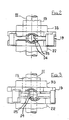
- a transmission unit is housed in a casing l0 and includes an input shaft ll and an output shaft l2.
- the input shaft ll passes through an opening l4 in the casing l0 and is driveably connected to a drive member l3: the shaft ll effectively connects the transmission unit to the drive of a motor (not shown).
- the drive member l3 is in splined engagement with the input shaft ll and is provided with a bearing assembly l5 having races l6 and l7 and ball bearings l8 so as to ensure free rotation of the drive member l3.
- the drive member l3 is provided with three equispaced drive dogs l9 extending outwardly therefrom.
- the dogs l9 are housed in clearance slots 20, 2l of an output ramp plate 22 and an input ramp plate 23 respectively.
- the output ramp plate and the input ramp plate in conjunction with three ball bearings 26 housed in grooves 24, 25 in the respective ramp plates form a ball and ramp actuator.
- the ball bearings 26 and dogs l9 are normally circumferentially interposed about the input shaft ll.
- the input ramp plate 23 is provided with a arrestor 27, which applies a preset drag torque to the ramp plate 23 to restrain the movement of the input ramp plate.
- the arrestor 27 comprises a circumferential collar 32 within which are housed six springs 28 and two screws 33; a pressure plate 29 which circumferential extends around and is in driveable contact by means of splines 30 with the input ramp plate 23, and a pair of brake plates 34 b which circumferential extend around the input ramp plate.
- the pressure plate is interposed between the brake plates 34 and between the interacting surfaces of the pressure plate 29 and the brake plate 34 b is placed a layer 34 a of brake material.
- the bearing assembly l5 is held in position between the input ramp plate 23 and the collar 32 by a shoulder 35 on the input ramp plate 23, an extension 36 on the collar 32, a sleeve 37 which circumferentially surrounds the input ramp plate 23 at a point near to the aperture l4 in the casing l0 and a protrusion 38 extending down from the casing top surface 39.
- the bearing assembly acts to hold a seal 40 in position between the sleeve 37, protrusion 38 and the top surface 39. This seal 40 prevents escape of oil housed within the casing l0 via aperture l4.
- the input shaft ll extends through a through bore 4l in the output shaft l2, and does not contact the said shaft l2.
- the input shaft ll is in driving contact with a transmission member 42, which may be part of the equipment being driven or a separate member provided to perform the function of transmitting the drive.
- the transmission member 42 is in splined contact with the output shaft and abuts a shoulder 43 of the output shaft l2.
- the drive from the input shaft ll is therefore transmitted by the following route, input shaft to transmission member 42 to output shaft.
- a metal circlip 53 is mounted in a metal groove 52 in the input shaft. Further a metal circlip 44 is mounted between the member 42 and the output shaft l2 to do the same function.
- the output shaft l2, input shaft ll and collar 42 extend through an aperture in a base member 45 on which the casing l0 is mounted; a sealing contact between base member and casing being provided by a seal 46.
- the base member may be mounted on or formed integrally with an ancillary piece of equipment.
- a bearing assembly 47 having circumferential races 48, 49 and ball bearings 50 is mounted between output shaft l2 and the base member 45 to ensure free rotation of the output shaft l2.
- the bearing assembly 47 also acts to hold a seal 5l in position in the base 45 around the output shaft l2. This seal prevents escape of oil in the unit through the aperture provided for the shafts etc.
- the output ramp plate 22 is in splined contact with the output shaft l2 and five pressure members 54.
- Each of the pressure members circumferentially extends around the output ramp plate, and forms part of a multi plate brake means.
- the multi plate brake means also includes six circumferential friction plates 55.
- Each of the pressure members 54 is interposed between two of the friction plates 55 with the lower-most friction plate being supported by a support ring 56 mounted on the base member 45.
- a layer 57 of brake material is provided between each of the interengaging surfaces of the pressure members 54 with the friction plates 55 as well as on the two non-engaging surfaces of the friction plates 55.
- the output ramp plate 22 is biased against the ball bearings 26 of the ball and ramp actuator by a reaction spring 58 which acts between a shoulder 59 of the output ramp plate 22 and a protrusion 60 on the output ramp plate 22.
Landscapes
- Engineering & Computer Science (AREA)
- General Engineering & Computer Science (AREA)
- Mechanical Engineering (AREA)
- Braking Arrangements (AREA)
Applications Claiming Priority (2)
| Application Number | Priority Date | Filing Date | Title |
|---|---|---|---|
| GB8609364 | 1986-04-17 | ||
| GB868609364A GB8609364D0 (en) | 1986-04-17 | 1986-04-17 | Rotary transmission |
Publications (3)
| Publication Number | Publication Date |
|---|---|
| EP0243050A2 true EP0243050A2 (de) | 1987-10-28 |
| EP0243050A3 EP0243050A3 (en) | 1989-07-12 |
| EP0243050B1 EP0243050B1 (de) | 1992-12-30 |
Family
ID=10596350
Family Applications (1)
| Application Number | Title | Priority Date | Filing Date |
|---|---|---|---|
| EP19870303142 Expired EP0243050B1 (de) | 1986-04-17 | 1987-04-10 | Rotationsübertragungseinheit |
Country Status (3)
| Country | Link |
|---|---|
| EP (1) | EP0243050B1 (de) |
| DE (1) | DE3783260T2 (de) |
| GB (1) | GB8609364D0 (de) |
Cited By (3)
| Publication number | Priority date | Publication date | Assignee | Title |
|---|---|---|---|---|
| CN107013612A (zh) * | 2017-03-30 | 2017-08-04 | 庆安集团有限公司 | 一种自紧式机械自动刹车装置 |
| WO2019110782A1 (de) * | 2017-12-08 | 2019-06-13 | Liebherr-Aerospace Lindenberg Gmbh | Dynamische rücklaufbremse mit dämpfungselement |
| EP4261429A1 (de) * | 2022-04-11 | 2023-10-18 | The Boeing Company | Bremse ohne rückwärtsgang für ein betätigungssystem und verfahren einer flugsteuerung |
Family Cites Families (4)
| Publication number | Priority date | Publication date | Assignee | Title |
|---|---|---|---|---|
| US3621958A (en) * | 1970-08-17 | 1971-11-23 | Saginaw Products Corp | Bidirectional no-back unit for ball screw utilizing roller cams |
| US3667578A (en) * | 1971-05-14 | 1972-06-06 | Harold Beck & Sons Inc | Bi-directional drive released brake |
| US4176733A (en) * | 1978-04-26 | 1979-12-04 | Sundstrand Corporation | Combination no-back brake and torque limiter assembly |
| DE3304431C2 (de) * | 1983-02-09 | 1986-10-16 | Liebherr-Aero-Technik Gmbh, 8998 Lindenberg | Servobremse |
-
1986
- 1986-04-17 GB GB868609364A patent/GB8609364D0/en active Pending
-
1987
- 1987-04-10 DE DE19873783260 patent/DE3783260T2/de not_active Expired - Fee Related
- 1987-04-10 EP EP19870303142 patent/EP0243050B1/de not_active Expired
Cited By (5)
| Publication number | Priority date | Publication date | Assignee | Title |
|---|---|---|---|---|
| CN107013612A (zh) * | 2017-03-30 | 2017-08-04 | 庆安集团有限公司 | 一种自紧式机械自动刹车装置 |
| CN107013612B (zh) * | 2017-03-30 | 2019-02-15 | 庆安集团有限公司 | 一种自紧式机械自动刹车装置 |
| WO2019110782A1 (de) * | 2017-12-08 | 2019-06-13 | Liebherr-Aerospace Lindenberg Gmbh | Dynamische rücklaufbremse mit dämpfungselement |
| US11603079B2 (en) | 2017-12-08 | 2023-03-14 | Liebherr-Aerospace Lindenberg Gmbh | Dynamic no-back brake having a damping element |
| EP4261429A1 (de) * | 2022-04-11 | 2023-10-18 | The Boeing Company | Bremse ohne rückwärtsgang für ein betätigungssystem und verfahren einer flugsteuerung |
Also Published As
| Publication number | Publication date |
|---|---|
| EP0243050A3 (en) | 1989-07-12 |
| EP0243050B1 (de) | 1992-12-30 |
| GB8609364D0 (en) | 1986-05-21 |
| DE3783260T2 (de) | 1993-07-22 |
| DE3783260D1 (de) | 1993-02-11 |
Similar Documents
| Publication | Publication Date | Title |
|---|---|---|
| US5743369A (en) | Wet clutch assembly | |
| US4480733A (en) | Energy absorbing bidirectional ratchet no-back apparatus | |
| US4425814A (en) | Torque limiting device | |
| EP0727594B1 (de) | Drehmomentbegrenzer | |
| EP0122015B1 (de) | Luftkompressor | |
| US7036644B2 (en) | Torque-transmitting mechanism with latching apparatus | |
| EP0850797B1 (de) | Zapfwellenantrieb mit selektiv betätigter Bremse | |
| CA2041770A1 (en) | Torque responsive brake | |
| WO2008002474A2 (en) | Separable under load shaft coupling | |
| WO2005106276A2 (en) | Secondary driven axle control | |
| US6692399B2 (en) | Differential torque limiter | |
| EP0243050B1 (de) | Rotationsübertragungseinheit | |
| US4997071A (en) | Automatic control system for a clutch coupling two rotating shafts | |
| DE10305434A1 (de) | Adapter und Getriebemotor | |
| AU746830B2 (en) | Driving arrangement with a free-wheel coupling | |
| US2240043A (en) | Automatic shaft brake device | |
| EP0189246B1 (de) | Lager mit Sicherheitseinrichtung | |
| US4809834A (en) | Multiple plate clutch release proportioning device | |
| GB2337017A (en) | Wet clutch/brake for a mechanical press | |
| EP1148275A1 (de) | Nutzfahrzeug Getriebe mit zwei steuerbaren hydrostatischen Motoren | |
| US6719106B1 (en) | Duplex skewed-roller brake disc | |
| US20040055837A1 (en) | Transmission brake | |
| EP0741065A2 (de) | Bremsvorrichtung und Verfahren zum Herstellen einer mehr konstanten Bremskraft | |
| EP0341873B1 (de) | Kupplungen | |
| EP0331362B1 (de) | Verzögerungsvorrichtung für Getriebeschaltung |
Legal Events
| Date | Code | Title | Description |
|---|---|---|---|
| PUAI | Public reference made under article 153(3) epc to a published international application that has entered the european phase |
Free format text: ORIGINAL CODE: 0009012 |
|
| AK | Designated contracting states |
Kind code of ref document: A2 Designated state(s): DE FR GB IT |
|
| PUAL | Search report despatched |
Free format text: ORIGINAL CODE: 0009013 |
|
| RHK1 | Main classification (correction) |
Ipc: F16D 67/00 |
|
| AK | Designated contracting states |
Kind code of ref document: A3 Designated state(s): DE FR GB IT |
|
| 17P | Request for examination filed |
Effective date: 19891222 |
|
| 17Q | First examination report despatched |
Effective date: 19910122 |
|
| GRAA | (expected) grant |
Free format text: ORIGINAL CODE: 0009210 |
|
| ITF | It: translation for a ep patent filed | ||
| AK | Designated contracting states |
Kind code of ref document: B1 Designated state(s): DE FR GB IT |
|
| REF | Corresponds to: |
Ref document number: 3783260 Country of ref document: DE Date of ref document: 19930211 |
|
| ET | Fr: translation filed | ||
| PG25 | Lapsed in a contracting state [announced via postgrant information from national office to epo] |
Ref country code: GB Effective date: 19930410 |
|
| PLBE | No opposition filed within time limit |
Free format text: ORIGINAL CODE: 0009261 |
|
| STAA | Information on the status of an ep patent application or granted ep patent |
Free format text: STATUS: NO OPPOSITION FILED WITHIN TIME LIMIT |
|
| GBPC | Gb: european patent ceased through non-payment of renewal fee |
Effective date: 19930410 |
|
| 26N | No opposition filed | ||
| PG25 | Lapsed in a contracting state [announced via postgrant information from national office to epo] |
Ref country code: FR Effective date: 19931229 |
|
| PG25 | Lapsed in a contracting state [announced via postgrant information from national office to epo] |
Ref country code: DE Effective date: 19940101 |
|
| REG | Reference to a national code |
Ref country code: FR Ref legal event code: ST |
|
| PG25 | Lapsed in a contracting state [announced via postgrant information from national office to epo] |
Ref country code: IT Free format text: LAPSE BECAUSE OF NON-PAYMENT OF DUE FEES;WARNING: LAPSES OF ITALIAN PATENTS WITH EFFECTIVE DATE BEFORE 2007 MAY HAVE OCCURRED AT ANY TIME BEFORE 2007. THE CORRECT EFFECTIVE DATE MAY BE DIFFERENT FROM THE ONE RECORDED. Effective date: 20050410 |