EP0243017A2 - Improvements in double glazing - Google Patents
Improvements in double glazing Download PDFInfo
- Publication number
- EP0243017A2 EP0243017A2 EP87302824A EP87302824A EP0243017A2 EP 0243017 A2 EP0243017 A2 EP 0243017A2 EP 87302824 A EP87302824 A EP 87302824A EP 87302824 A EP87302824 A EP 87302824A EP 0243017 A2 EP0243017 A2 EP 0243017A2
- Authority
- EP
- European Patent Office
- Prior art keywords
- glass
- lead
- facing
- glasses
- pieces
- Prior art date
- Legal status (The legal status is an assumption and is not a legal conclusion. Google has not performed a legal analysis and makes no representation as to the accuracy of the status listed.)
- Granted
Links
Images

Classifications
-
- B—PERFORMING OPERATIONS; TRANSPORTING
- B44—DECORATIVE ARTS
- B44C—PRODUCING DECORATIVE EFFECTS; MOSAICS; TARSIA WORK; PAPERHANGING
- B44C5/00—Processes for producing special ornamental bodies
- B44C5/08—Leaded lights
-
- B—PERFORMING OPERATIONS; TRANSPORTING
- B44—DECORATIVE ARTS
- B44F—SPECIAL DESIGNS OR PICTURES
- B44F1/00—Designs or pictures characterised by special or unusual light effects
- B44F1/06—Designs or pictures characterised by special or unusual light effects produced by transmitted light, e.g. transparencies, imitations of glass paintings
- B44F1/066—Designs or pictures characterised by special or unusual light effects produced by transmitted light, e.g. transparencies, imitations of glass paintings comprising at least two transparent elements, e.g. sheets, layers
-
- E—FIXED CONSTRUCTIONS
- E06—DOORS, WINDOWS, SHUTTERS, OR ROLLER BLINDS IN GENERAL; LADDERS
- E06B—FIXED OR MOVABLE CLOSURES FOR OPENINGS IN BUILDINGS, VEHICLES, FENCES OR LIKE ENCLOSURES IN GENERAL, e.g. DOORS, WINDOWS, BLINDS, GATES
- E06B3/00—Window sashes, door leaves, or like elements for closing wall or like openings; Layout of fixed or moving closures, e.g. windows in wall or like openings; Features of rigidly-mounted outer frames relating to the mounting of wing frames
- E06B3/66—Units comprising two or more parallel glass or like panes permanently secured together
- E06B3/6604—Units comprising two or more parallel glass or like panes permanently secured together comprising false glazing bars or similar decorations between the panes
Definitions
- This invention relates to a sealed double glazed leaded light unit which has particular reference to a stained glass unit.
- EP-A-0085732 discloses a substitute sealed double glazed stained glass unit constructed by sticking lead strips and coloured plastics sheets onto the inside of one of the clear glass boundary sheets. It has also been proposed to paint areas of the inside surface of one of the clear glass boundary sheets before completing the sealed unit but to even a relatively inexperienced eye plastics sheets and painted areas are seen to be substitutes for real stained glass.
- a double glazed leaded light unit comprises first and second facing sheets of clear transparent material, a perimeter frame spacing the facing sheets apart and hermetically sealing the gap formed between the facing sheets, and located within the gap, the lead strips and glass pieces of a leaded light, wherein the pieces of glass are adhered directly, at edge regions thereof, to the inside of the first of the facing sheets, a first framework of lead strips is secured over the edges of the pieces of glass within the gap and a second framework of lead strips is secured on the outside of the first facing sheet to overlie the edges of the pieces of glass disposed within the gap.
- the facing sheets would be of clear glass but a glass-substitute material is not ruled out for either or both of these sheets.
- An adhesive suitable for adhering the pieces of glass to the inside of the first facing sheet is pure silicone. If a different adhesive is used, it should be degassable to leave a non-volatile residue.
- the lead framework can be made from self-adhesive or T-section lead strip, the joins between the lengths of lead strip that make up the framework preferably being covered with an area of blow pipe melted solder.
- the perimeter frame can be constructed from conventional British Standard approved materials.
- Self adhesive lead strip can be used to made the second external framework, the joins between strips again preferably being covered with areas of melted solder.
- any of the glasses used for a conventional stained glass panel can be incorporated in the gap, thus opening the possibility of incorporating any available coloured/clear/obscured glasses into the unit.
- a method of incorporating the different glasses of a leaded stained glass panel into a sealed double glazed unit comprises adhering edge regions of adjacent glasses of the stained glass panel together and to a first trans parent facing sheet, locating a first frame of lead strips over the adjacent edge regions so that a respective strip of the frame overlies each edge region, combining the first facing sheet with a second facing sheet into a hermetically sealed double glazed unit so that the stained glasses and first lead frame lie within the gap between the facing sheets, and adhering a second lead frame on the outer face of the first facing sheet to obscure the edge regions of the adjacent glasses viewable through the first facing sheet.
- the area of the stained glass panel may represent substantially the entire area of the sealed unit or may be located in the sealed unit with a perimeter of the facing sheets therearound.
- both facing sheets are transparent and preferably are of glass.
- the second facing sheet can be translucent or obscured glass in some applications.
- T-shaped lead enables an even more realistic double glazed stained glass window to be produced since the framework of T-shaped lead can be built up by cutting and soldering as the pattern of included glasses is assembled on a support in a manner very similar to that used for a conventional stained glass window.
- the framework When the framework is complete, it and its included glasses can be inverted and adhesive applied to regions of the frame and glass (e.g. to corner regions where lead strips meet) so that one facing sheet of the eventual double glazed unit can be pressed down onto the inverted stained glass unit to adhere it to the facing sheet.
- the hermetically sealed double glazed unit can then be assembled exactly as described before.
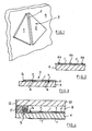
- Figure 1 of the drawing shows two pieces of glass 1 and 2 which constitute part of a stained glass panel 3 resting on a rectangular sheet 4 of float glass.
- An air-drying silicone adhesive is "gunned" into the gap 5 between the pieces 1 and 2 and the pieces are slid together on the sheet 4 to close the gap 5. This operation ensures that adhesive 6 fills the gap 5 and forms an upstand 6a overlying the gap on the upper surface of each piece 1 and 2 ( Figure 2).
- the other pieces of glass, preferably all of similar thickness, required to complete the stained glass panel 3 are applied to the facing sheet 4 in a similar way until the pattern is completed.
- the joints between the strips 7 are then soldered (e.g. in the same way in which the lead spacer bars of a conventional stained glass panel 3 would be soldered) and the perimeter of the panel 3 is completed with edge strips 7a of lead which may be bent down to contact the sheet 4.
- the panel 3 is now located in the gap 8 of a conventionally produced double-glazed sealed unit using a dessicant-filled perimeter frame 9 spacing the sheet 4 from a further glass facing sheet 10.
- a conventional edge-sealing mastic 11 and edge strip 12 completes the sealing of the unit.
- the mastic 11 may be Bostic 318 0 and the adhesive 6, Dow Corning 781.
- FIG 6 shows, in cross-section part of a double glazed unit made by a modified method in which a framework 20 of T-shaped lead strips 21 (see Figure 5) is built up around pieces 22 of glass.
- the upright of the T is as long as the glass pieces 22 are thick and is located in the gap between adjacent pieces 22.
- the horizontal bar of the T overlies the edge regions of the pieces 22 and the lengths of lead strip 21 are blow-pipe soldered at 23 as the assembly proceeds on a flat supporting base 24 until the pattern is complete.
- L-shaped edge pieces 25 of lead can be used to mark the outer boundary of the pattern of stained glass.
- the base 24 and its supported pattern of glass pieces and lead framework is now inverted and a silicone adhesive (e.g. Dow Corning 781) is "gunned" onto the joints between the lead strips 21 and all around the outer boundary of the pattern.
- a silicone adhesive e.g. Dow Corning 781
- a sheet of plane transparent glass (26 - see Figure 6) onto the inverted pattern of glass and lead, secures the components together and provided the amount of adhesive applied at each location 23 and around the outer edges is not enough to spread beyond the limits of the horizontal bar of the T-shaped lead strips 21 or the L-shaped edge pieces 25, the adhesive will not be visible when the pattern of glass and lead is viewed through the sheet 26, in the hemetically sealed double glazed unit.
- the sheet 26 is combined with a second sheet of glass 29, edge mastic 30 and dessicant filled framing strip 31 to form a hermetically sealed unit.
- a second framework 27 of self-adhesive lead strips 28 is then applied on the exposed face of the sheet 26 to overlie the strips 21 and edge pieces 25 of the inner framework 20 to complete the double glazed unit.
Abstract
Description
- This invention relates to a sealed double glazed leaded light unit which has particular reference to a stained glass unit.
- It has not proved possible to produce a sealed double glazed stained glass unit with a conventional leaded stained glass panel as one boundary wall of the sealed unit. It has been proposed (GB-A-1426551, 1147030 and 2137680 to locate a conventional leaded stained glass panel in the gap between the clear glass boundary sheets of a conventional sealed double glazed unit but this arrangement is optically unsatisfactory under certain lighting conditions.
- It has also been proposed (in GB-A-1491696) to make a double glazed leaded light by securing raised strip members to both sides of one of the clear glass boundary walls of a conventional double glazed unit.
- EP-A-0085732 discloses a substitute sealed double glazed stained glass unit constructed by sticking lead strips and coloured plastics sheets onto the inside of one of the clear glass boundary sheets. It has also been proposed to paint areas of the inside surface of one of the clear glass boundary sheets before completing the sealed unit but to even a relatively inexperienced eye plastics sheets and painted areas are seen to be substitutes for real stained glass.
- According to one aspect of the invention, a double glazed leaded light unit comprises first and second facing sheets of clear transparent material, a perimeter frame spacing the facing sheets apart and hermetically sealing the gap formed between the facing sheets, and located within the gap, the lead strips and glass pieces of a leaded light, wherein the pieces of glass are adhered directly, at edge regions thereof, to the inside of the first of the facing sheets, a first framework of lead strips is secured over the edges of the pieces of glass within the gap and a second framework of lead strips is secured on the outside of the first facing sheet to overlie the edges of the pieces of glass disposed within the gap.
- Normally the facing sheets would be of clear glass but a glass-substitute material is not ruled out for either or both of these sheets. An adhesive suitable for adhering the pieces of glass to the inside of the first facing sheet is pure silicone. If a different adhesive is used, it should be degassable to leave a non-volatile residue. The lead framework can be made from self-adhesive or T-section lead strip, the joins between the lengths of lead strip that make up the framework preferably being covered with an area of blow pipe melted solder.
- The perimeter frame can be constructed from conventional British Standard approved materials.
- Self adhesive lead strip can be used to made the second external framework, the joins between strips again preferably being covered with areas of melted solder.
- Any of the glasses used for a conventional stained glass panel can be incorporated in the gap, thus opening the possibility of incorporating any available coloured/clear/obscured glasses into the unit.
- According to a further aspect of the invention, a method of incorporating the different glasses of a leaded stained glass panel into a sealed double glazed unit comprises adhering edge regions of adjacent glasses of the stained glass panel together and to a first trans parent facing sheet, locating a first frame of lead strips over the adjacent edge regions so that a respective strip of the frame overlies each edge region, combining the first facing sheet with a second facing sheet into a hermetically sealed double glazed unit so that the stained glasses and first lead frame lie within the gap between the facing sheets, and adhering a second lead frame on the outer face of the first facing sheet to obscure the edge regions of the adjacent glasses viewable through the first facing sheet.
- The area of the stained glass panel may represent substantially the entire area of the sealed unit or may be located in the sealed unit with a perimeter of the facing sheets therearound.
- Preferably both facing sheets are transparent and preferably are of glass. The second facing sheet can be translucent or obscured glass in some applications.
- The use of T-shaped lead enables an even more realistic double glazed stained glass window to be produced since the framework of T-shaped lead can be built up by cutting and soldering as the pattern of included glasses is assembled on a support in a manner very similar to that used for a conventional stained glass window. When the framework is complete, it and its included glasses can be inverted and adhesive applied to regions of the frame and glass (e.g. to corner regions where lead strips meet) so that one facing sheet of the eventual double glazed unit can be pressed down onto the inverted stained glass unit to adhere it to the facing sheet. The hermetically sealed double glazed unit can then be assembled exactly as described before.
- The invention will now be further described by the following examples read in conjunction with the accompany ing drawings in which
- Figures 1 to 4 show in perspective and cross-section various stages in the production of a sealed stained glass unit by a first method according to this invention, and
- Figures 5 and 6 show in perspective and cross-section a modified construction resuling from a second method according to this invention.
- Figure 1 of the drawing shows two pieces of
glass stained glass panel 3 resting on arectangular sheet 4 of float glass. An air-drying silicone adhesive is "gunned" into thegap 5 between thepieces sheet 4 to close thegap 5. This operation ensures that adhesive 6 fills thegap 5 and forms an upstand 6a overlying the gap on the upper surface of eachpiece 1 and 2 (Figure 2). - The other pieces of glass, preferably all of similar thickness, required to complete the
stained glass panel 3 are applied to the facingsheet 4 in a similar way until the pattern is completed. - When all the pieces of glass are in place, the upstands 6a overlying each gap are sliced off flush with the upper surfaces of the glass pieces (e.g. using a razor blade) and
narrow strips 7 of self-adhesive lead strip (e.g. 9.0 mm wide and 1.0 mm thick) are cut and stuck over each adhesive-filled gap. (Figure 3) - The joints between the
strips 7 are then soldered (e.g. in the same way in which the lead spacer bars of a conventionalstained glass panel 3 would be soldered) and the perimeter of thepanel 3 is completed withedge strips 7a of lead which may be bent down to contact thesheet 4. - The
panel 3 is now located in thegap 8 of a conventionally produced double-glazed sealed unit using a dessicant-filledperimeter frame 9 spacing thesheet 4 from a furtherglass facing sheet 10. A conventional edge-sealing mastic 11 andedge strip 12 completes the sealing of the unit. - To finish the sealed unit, more pieces of self-
adhesive lead strip 7 are applied to the exposed face of thesheet 4 in positions to mask theunderlying gaps 5 and the joins between these strips are soldered as before. In practice this means that two substantially similar but (opposite handed) lead frameworks have been used - one located inside thegap 8 and one outside (Figure 4). - A unit manufactured as described above has been tested by Bostik laboratories for initial dew point and humidity cycling and was tested to below -60°C without failure. The test to BS 5713 was satisfactorily completed. Two years after manufacture the humidity seal appears to be perfect.
- Visually, in no lighting condition, does the sealed unit appear to be other than genuine.
- The
mastic 11 may be Bostic 318 0 and the adhesive 6, Dow Corning 781. - Figure 6 shows, in cross-section part of a double glazed unit made by a modified method in which a
framework 20 of T-shaped lead strips 21 (see Figure 5) is built up aroundpieces 22 of glass. The upright of the T is as long as theglass pieces 22 are thick and is located in the gap betweenadjacent pieces 22. The horizontal bar of the T overlies the edge regions of thepieces 22 and the lengths oflead strip 21 are blow-pipe soldered at 23 as the assembly proceeds on a flat supportingbase 24 until the pattern is complete. L-shaped edge pieces 25 of lead can be used to mark the outer boundary of the pattern of stained glass. - The
base 24 and its supported pattern of glass pieces and lead framework is now inverted and a silicone adhesive (e.g. Dow Corning 781) is "gunned" onto the joints between thelead strips 21 and all around the outer boundary of the pattern. - Pressing a sheet of plane transparent glass (26 - see Figure 6) onto the inverted pattern of glass and lead, secures the components together and provided the amount of adhesive applied at each
location 23 and around the outer edges is not enough to spread beyond the limits of the horizontal bar of the T-shaped lead strips 21 or the L-shaped edge pieces 25, the adhesive will not be visible when the pattern of glass and lead is viewed through thesheet 26, in the hemetically sealed double glazed unit. Thesheet 26 is combined with a second sheet ofglass 29, edge mastic 30 and dessicant filledframing strip 31 to form a hermetically sealed unit. Asecond framework 27 of self-adhesive lead strips 28 is then applied on the exposed face of thesheet 26 to overlie thestrips 21 andedge pieces 25 of theinner framework 20 to complete the double glazed unit.
Claims (7)
Priority Applications (1)
| Application Number | Priority Date | Filing Date | Title |
|---|---|---|---|
| AT87302824T ATE81705T1 (en) | 1986-04-17 | 1987-04-01 | DOUBLE GLAZING. |
Applications Claiming Priority (2)
| Application Number | Priority Date | Filing Date | Title |
|---|---|---|---|
| GB868609460A GB8609460D0 (en) | 1986-04-17 | 1986-04-17 | Double glazing |
| GB8609460 | 1986-04-17 |
Publications (3)
| Publication Number | Publication Date |
|---|---|
| EP0243017A2 true EP0243017A2 (en) | 1987-10-28 |
| EP0243017A3 EP0243017A3 (en) | 1988-03-23 |
| EP0243017B1 EP0243017B1 (en) | 1992-10-21 |
Family
ID=10596404
Family Applications (1)
| Application Number | Title | Priority Date | Filing Date |
|---|---|---|---|
| EP87302824A Expired - Lifetime EP0243017B1 (en) | 1986-04-17 | 1987-04-01 | Improvements in double glazing |
Country Status (4)
| Country | Link |
|---|---|
| EP (1) | EP0243017B1 (en) |
| AT (1) | ATE81705T1 (en) |
| DE (1) | DE3782269T2 (en) |
| GB (2) | GB8609460D0 (en) |
Cited By (3)
| Publication number | Priority date | Publication date | Assignee | Title |
|---|---|---|---|---|
| GB2199609A (en) * | 1987-01-02 | 1988-07-13 | Hickman James A A | Leaded lights |
| GB2220023A (en) * | 1988-06-21 | 1989-12-28 | D & P R Ensor Limited | Glazed window unit |
| US5908674A (en) * | 1995-12-13 | 1999-06-01 | E. I. Du Pont De Nemours And Company | Impact-resisting glazing structure |
Families Citing this family (4)
| Publication number | Priority date | Publication date | Assignee | Title |
|---|---|---|---|---|
| US7195824B2 (en) * | 2004-08-20 | 2007-03-27 | Ged Integrated Solutions, Inc. | Decorative tape |
| RU2516972C1 (en) * | 2013-01-09 | 2014-05-20 | Федеральное государственное бюджетное образовательное учреждение высшего профессионального образования "Санкт-Петербургский государственный университет технологии и дизайна" (СПГУТД) | Production of mosaic article |
| RU168071U1 (en) * | 2015-09-16 | 2017-01-17 | Татьяна Юрьевна Русова | MODULAR MOSAIC SYSTEM |
| GB2550838A (en) * | 2016-04-01 | 2017-12-06 | Charles John Lloyd-Winder Matthew | Improvement to double glazing leaded and stained glass |
Citations (3)
| Publication number | Priority date | Publication date | Assignee | Title |
|---|---|---|---|---|
| GB1491696A (en) * | 1974-12-10 | 1977-11-09 | H & F Precise Castings Ltd | Double glazed window units |
| DE3029613A1 (en) * | 1980-08-05 | 1982-03-18 | Karl Otto 5276 Wiehl Platz | Decorative double glazing - with ornamental patterns and foil strips bonded to inside of one pane |
| EP0085732A1 (en) * | 1982-02-10 | 1983-08-17 | Stained Glass Overlay, Inc. | Simulated stained and leaded glass windows |
Family Cites Families (1)
| Publication number | Priority date | Publication date | Assignee | Title |
|---|---|---|---|---|
| US4312688A (en) * | 1980-02-11 | 1982-01-26 | Brodis Eric P | Method and apparatus for making simulated stained-glass |
-
1986
- 1986-04-17 GB GB868609460A patent/GB8609460D0/en active Pending
-
1987
- 1987-04-01 EP EP87302824A patent/EP0243017B1/en not_active Expired - Lifetime
- 1987-04-01 AT AT87302824T patent/ATE81705T1/en not_active IP Right Cessation
- 1987-04-01 DE DE8787302824T patent/DE3782269T2/en not_active Expired - Fee Related
- 1987-04-01 GB GB8707777A patent/GB2188359B/en not_active Expired
Patent Citations (3)
| Publication number | Priority date | Publication date | Assignee | Title |
|---|---|---|---|---|
| GB1491696A (en) * | 1974-12-10 | 1977-11-09 | H & F Precise Castings Ltd | Double glazed window units |
| DE3029613A1 (en) * | 1980-08-05 | 1982-03-18 | Karl Otto 5276 Wiehl Platz | Decorative double glazing - with ornamental patterns and foil strips bonded to inside of one pane |
| EP0085732A1 (en) * | 1982-02-10 | 1983-08-17 | Stained Glass Overlay, Inc. | Simulated stained and leaded glass windows |
Cited By (5)
| Publication number | Priority date | Publication date | Assignee | Title |
|---|---|---|---|---|
| GB2199609A (en) * | 1987-01-02 | 1988-07-13 | Hickman James A A | Leaded lights |
| GB2199609B (en) * | 1987-01-02 | 1990-11-14 | Hickman James A A | Improvements in or relating to glazing assemblies |
| GB2220023A (en) * | 1988-06-21 | 1989-12-28 | D & P R Ensor Limited | Glazed window unit |
| GB2220023B (en) * | 1988-06-21 | 1991-12-04 | D & P R Ensor Limited | A glazed window unit and method of manufacture therefor |
| US5908674A (en) * | 1995-12-13 | 1999-06-01 | E. I. Du Pont De Nemours And Company | Impact-resisting glazing structure |
Also Published As
| Publication number | Publication date |
|---|---|
| GB2188359A (en) | 1987-09-30 |
| GB2188359B (en) | 1989-11-29 |
| GB8707777D0 (en) | 1987-05-07 |
| GB8609460D0 (en) | 1986-05-21 |
| EP0243017B1 (en) | 1992-10-21 |
| DE3782269D1 (en) | 1992-11-26 |
| DE3782269T2 (en) | 1993-05-06 |
| EP0243017A3 (en) | 1988-03-23 |
| ATE81705T1 (en) | 1992-11-15 |
Similar Documents
| Publication | Publication Date | Title |
|---|---|---|
| US4149348A (en) | Multiple glazed unit having inner sheet mounted within a spacer | |
| US3054153A (en) | Double pane element | |
| US5271973A (en) | Architectural glass panel | |
| GB1147030A (en) | Glazing units | |
| ATE124755T1 (en) | INSULATING GLAZING WITH INSULATING SPACER. | |
| NO972902D0 (en) | Method and apparatus for making specially ordered glass compositions | |
| EP0243017B1 (en) | Improvements in double glazing | |
| WO1992020536A1 (en) | Method and apparatus for creating design insulated glass | |
| ES433028A1 (en) | Laminated glazing pane | |
| GB2020684B (en) | Thin film electroluminescent display panel sealed by glass substrates | |
| PT753639E (en) | FIRE-RESISTANT VIDRACA | |
| ES2052150T3 (en) | MINIMUM LEAKAGE GLAZING SYSTEM, FOR A SPACE FRAME STRUCTURE. | |
| FR2358367A1 (en) | GLASS FRIT COMPOSITION FOR SEALING GLASS TO WINDOWS | |
| SE9100574D0 (en) | COMPOSITION GLASS GLASS PANEL | |
| DK8286D0 (en) | PROCEDURE FOR MAKING A VERY THIN GLASS METAL OXIDE COVER | |
| EP1211377A2 (en) | Glass panel and its method of manufacturing | |
| JP2002167244A (en) | Method of fabricating glass panel | |
| JPS55138715A (en) | Liquid crystal display element | |
| EP0377880A1 (en) | System for controlling possible shifting of panels in structural facades | |
| JP2589992Y2 (en) | Double glazing | |
| GB2222194A (en) | Glazing | |
| GB1491696A (en) | Double glazed window units | |
| KR20000005660U (en) | Double layer glass | |
| JP2023113353A (en) | Double glazing for joining and structure for joining double glazings | |
| FR2424887A1 (en) | Double glazed window structure assembly system - delivers glue by nozzle between panes and frame to fill slot completely |
Legal Events
| Date | Code | Title | Description |
|---|---|---|---|
| PUAI | Public reference made under article 153(3) epc to a published international application that has entered the european phase |
Free format text: ORIGINAL CODE: 0009012 |
|
| AK | Designated contracting states |
Kind code of ref document: A2 Designated state(s): AT BE CH DE FR GB LI NL SE |
|
| PUAL | Search report despatched |
Free format text: ORIGINAL CODE: 0009013 |
|
| AK | Designated contracting states |
Kind code of ref document: A3 Designated state(s): AT BE CH DE FR GB LI NL SE |
|
| 17P | Request for examination filed |
Effective date: 19880827 |
|
| 17Q | First examination report despatched |
Effective date: 19891006 |
|
| GRAA | (expected) grant |
Free format text: ORIGINAL CODE: 0009210 |
|
| AK | Designated contracting states |
Kind code of ref document: B1 Designated state(s): AT BE CH DE FR GB LI NL SE |
|
| PG25 | Lapsed in a contracting state [announced via postgrant information from national office to epo] |
Ref country code: SE Effective date: 19921021 Ref country code: NL Effective date: 19921021 Ref country code: AT Effective date: 19921021 |
|
| REF | Corresponds to: |
Ref document number: 81705 Country of ref document: AT Date of ref document: 19921115 Kind code of ref document: T |
|
| REF | Corresponds to: |
Ref document number: 3782269 Country of ref document: DE Date of ref document: 19921126 |
|
| ET | Fr: translation filed | ||
| NLV1 | Nl: lapsed or annulled due to failure to fulfill the requirements of art. 29p and 29m of the patents act | ||
| PLBE | No opposition filed within time limit |
Free format text: ORIGINAL CODE: 0009261 |
|
| STAA | Information on the status of an ep patent application or granted ep patent |
Free format text: STATUS: NO OPPOSITION FILED WITHIN TIME LIMIT |
|
| 26N | No opposition filed | ||
| PGFP | Annual fee paid to national office [announced via postgrant information from national office to epo] |
Ref country code: CH Payment date: 19950524 Year of fee payment: 9 |
|
| PG25 | Lapsed in a contracting state [announced via postgrant information from national office to epo] |
Ref country code: LI Effective date: 19960430 Ref country code: CH Effective date: 19960430 |
|
| REG | Reference to a national code |
Ref country code: CH Ref legal event code: PL |
|
| REG | Reference to a national code |
Ref country code: GB Ref legal event code: IF02 |
|
| PGFP | Annual fee paid to national office [announced via postgrant information from national office to epo] |
Ref country code: FR Payment date: 20040428 Year of fee payment: 18 |
|
| PGFP | Annual fee paid to national office [announced via postgrant information from national office to epo] |
Ref country code: BE Payment date: 20040510 Year of fee payment: 18 |
|
| PGFP | Annual fee paid to national office [announced via postgrant information from national office to epo] |
Ref country code: DE Payment date: 20040629 Year of fee payment: 18 |
|
| PGFP | Annual fee paid to national office [announced via postgrant information from national office to epo] |
Ref country code: GB Payment date: 20050331 Year of fee payment: 19 |
|
| PG25 | Lapsed in a contracting state [announced via postgrant information from national office to epo] |
Ref country code: BE Free format text: LAPSE BECAUSE OF NON-PAYMENT OF DUE FEES Effective date: 20050430 |
|
| BERE | Be: lapsed |
Owner name: *TENBY & PENNY CO. LTD Effective date: 20050430 |
|
| PG25 | Lapsed in a contracting state [announced via postgrant information from national office to epo] |
Ref country code: DE Free format text: LAPSE BECAUSE OF NON-PAYMENT OF DUE FEES Effective date: 20051101 |
|
| PG25 | Lapsed in a contracting state [announced via postgrant information from national office to epo] |
Ref country code: FR Free format text: LAPSE BECAUSE OF NON-PAYMENT OF DUE FEES Effective date: 20051230 |
|
| REG | Reference to a national code |
Ref country code: FR Ref legal event code: ST Effective date: 20051230 |
|
| PG25 | Lapsed in a contracting state [announced via postgrant information from national office to epo] |
Ref country code: GB Free format text: LAPSE BECAUSE OF NON-PAYMENT OF DUE FEES Effective date: 20060401 |
|
| GBPC | Gb: european patent ceased through non-payment of renewal fee |
Effective date: 20060401 |
|
| BERE | Be: lapsed |
Owner name: *TENBY & PENNY CO. LTD Effective date: 20050430 |